EP1997629A2 - Presse rotative - Google Patents
Presse rotative Download PDFInfo
- Publication number
- EP1997629A2 EP1997629A2 EP08009612A EP08009612A EP1997629A2 EP 1997629 A2 EP1997629 A2 EP 1997629A2 EP 08009612 A EP08009612 A EP 08009612A EP 08009612 A EP08009612 A EP 08009612A EP 1997629 A2 EP1997629 A2 EP 1997629A2
- Authority
- EP
- European Patent Office
- Prior art keywords
- printing
- printing unit
- web
- unit
- rotary printing
- Prior art date
- Legal status (The legal status is an assumption and is not a legal conclusion. Google has not performed a legal analysis and makes no representation as to the accuracy of the status listed.)
- Withdrawn
Links
Images


Classifications
-
- B—PERFORMING OPERATIONS; TRANSPORTING
- B41—PRINTING; LINING MACHINES; TYPEWRITERS; STAMPS
- B41F—PRINTING MACHINES OR PRESSES
- B41F13/00—Common details of rotary presses or machines
- B41F13/0024—Frames
Definitions
- the invention relates to a rotary printing machine, and in particular a rotary printing machine, which can still be installed in a particularly space-saving manner at its respective installation site with high printing capacity and high system flexibility.
- this constant need is based on the fact that in larger printing presses, especially higher-heeled printing presses, more workers are needed to operate the system, which can significantly increase labor costs. Therefore, the operators of printing systems strive to procure compact systems that are to operate with the least possible personnel costs.
- a conventional printing unit as used in such a stunted rotary printing presses, for example, is the H-pressure unit with an 8-cylinder system (rubber-rubber) used by MAN Roland AG in their "CROMOMAN” printing press.
- the "CROMOMAN” two such H-printing units are stacked or stacked to a printing tower, whereby for high color and page capacity in a small space, for example, a so-called 4/4-color printing (the application of four colors on each side of a In this configuration, the paper web is passed substantially vertically through the printing units, each printing unit having four printing locations or printing units, ie two for each web page.
- the newly developed printing units which now incorporate more pressure points, have a higher weight than conventional printing units. Since in rotary printing presses, such as the "CROMOMAN", each upper printing unit is placed directly on the respective lower printing unit, the entire weight of the upper printing unit rests on the lower printing unit. If the weight of the printing units now increases, this can, for example, lead to unwanted deformations on the lower printing unit.
- such plant configurations are generally limited in that the printing units stacked on top of each other should, if possible, have the same width and depth dimensions to allow such stacking.
- this arrangement can For example, the printing units transmit vibrations of one printing unit of the printing tower to the other printing unit of the printing tower.
- the object of the invention is to provide a rotary printing press in which printing units arranged one above another are physically decoupled from one another such that unwanted interactions between the printing units are reliably avoided.
- a rotary printing press comprises a printing tower having a first printing unit arranged on a support base and a second printing unit arranged above the first printing unit and a substructure supporting the second printing unit so that the weight of the second printing unit Pressure unit on the substructure assembly loads.
- such a plant configuration offers the advantage that, as the weight of the upper pressure unit rests on the substructure, the lower pressure unit is not exposed to excessive stresses which could lead to deformations on the pressure unit.
- deformations may, for example, be deformations of the bearing seats or of the bearings for the cylinders or rollers of the printing unit.
- the two printing units are vibrationally decoupled from each other, whereby the bearings of the printing units are spared and the print quality is improved.
- the substructure has a horizontal section and a vertical section.
- This embodiment of the substructure is robust and can be easily integrated into the printing press.
- the vertical section has upper ends and lower ends
- the horizontal section has lateral ends which are supported at the upper ends of the vertical section.
- the lower ends of the vertical portion are supported on the support base.
- the horizontal section extends between the first printing unit and the second printing unit.
- This embodiment can be realized, for example, as a continuous or interrupted portal construction or as a self-supporting construction using, for example, steel beams and / or concrete elements, wherein the horizontal section is fastened or supported on the vertical section. This is inexpensive and easily integrated into the printing press.
- the horizontal portion has an upper surface on which the second printing unit is arranged.
- This embodiment is advantageous in that the upper pressure unit is mounted in the same way as the lower pressure unit, namely standing on its underside, so that no additional fastening means or structural changes to the upper pressure unit must be provided in comparison to the lower pressure unit in order to set this up ,
- the horizontal section between its lateral ends on a width dimension which is at least as large as a width dimension of the first printing unit and extends substantially parallel thereto.
- This embodiment ensures a secure state of the upper printing unit and a correct alignment of this to the lower printing unit of the printing tower. Further, if the width dimension of the horizontal portion is e.g. is larger than that of the lower printing unit, the upper and second printing units have a larger width dimension than the lower and first printing units, respectively. This gives increased flexibility in the system configuration.
- the vertical section between its lower and upper ends has a height dimension which is at least as large as a height dimension of the first printing unit and extends substantially parallel thereto.
- This refinement has the advantage that the substructure arrangement can be realized on the one hand with minimal dimensions and on the other hand if the height dimension of the vertical section is greater than the height dimension of the first section Pressure unit is, if necessary, space between two printing units can be created.
- the vertical portion has at least two vertical elements, each having an upper end and a lower end, wherein at the upper ends of the vertical elements, the lateral ends of the horizontal portion are supported.
- This portal-like configuration of the substructure is simple, robust and inexpensive.
- the first printing unit is arranged between the at least two vertical elements.
- This embodiment offers the advantage that, if several such printing towers are arranged side by side, a modular structure of the individual printing towers is ensured so that printing towers can be added or omitted as needed or customized.
- the horizontal portion has two elongated, alongside each other spaced apart support elements each having two longitudinal ends, wherein the two longitudinal ends of the support elements are respectively supported at the upper ends of the vertical portion.
- This embodiment has the advantages that on the one hand, the upper pressure unit can be supported to save material and on the other hand space between the support elements is available, which can be used for design and technological purposes.
- the printing units each have at least one pressure point, at least two pressure points or eight pressure points.
- the vertical elements are integrated into two opposite side walls of the first printing unit.
- This embodiment has the advantage that the substructure can be integrated in a particularly space-saving and material-saving in the printing press, which costs are saved.
- the vertical elements are formed by two opposite side walls of the first printing unit, wherein axes of rotation of the cylinders of the first printing unit extend substantially parallel to these side walls.
- the vertical elements are formed by those side walls of the first printing unit which do not receive bearings for the cylinders, such as blanket cylinders, impression cylinders and inking cylinders, of the first printing unit.
- This embodiment additionally saves material and costs, nevertheless ensuring that the side walls of the first printing unit which receive the bearings for the cylinders are completely free of any pressure loads by the second printing unit.
- a first web guide is provided between the first printing unit and the second printing unit for introducing and / or removing a web to be printed or printed between the first printing unit and the second printing unit.
- this embodiment offers the advantage that a web to be printed or printed can be passed from an adjacent web changer or an adjacent printing tower between the first printing unit and the second printing unit for further processing, such as folding.
- this configuration it is possible to insert a web to be printed or printed from an adjacent web changer or printing tower into one of the first and second printing units for printing. This increases the flexibility of the printing press with regard to the possible pressure variants.
- the first web guide has a turning device and / or a deflecting device for engaging and / or selecting at least one web in or out of the printing units.
- the web after passing through one of the printing units, the web can be led horizontally out of the printing unit relative to the vertical axis by 90 degrees, for example, and then fed to the former fed to a folding apparatus.
- a second web can then be used, for example, in the other of the printing units by means of a deflection roller and / or a turning bar to be printed in this printing unit.
- This second path can be brought from an adjacent printing tower or an adjacent reel changer.
- the first web guide on a railway securing device is a railway securing device.
- devices such as a web tension control device and / or a register control device can be integrated to save space in the space between the first and second printing unit.
- the printing press can be made even more compact.
- the first web guide is mounted on the horizontal portion.
- the first web guide can be easily integrated or installed in the horizontal section, so that in addition space and material can be saved. This additionally favors the compactness of the printing press and reduces costs, since no additional mounting devices for the first web guide must be provided,
- a second web guide is integrated into the vertical section for passing at least one printed or printed web through the vertical section.
- This embodiment has the advantage that one or more webs can be performed space-saving and flexible by the printing press.
- a printed or to be printed web can be guided by an adjacent printing tower or an adjacent roll changer to, for example, the second printing unit and are used for printing in this.
- a third web guide is provided under the first printing unit for introducing or removing a web to be printed or printed in or out of the first printing unit.
- This refinement makes the printing machine even more flexible adaptable to the respective print job to be performed.
- the third web guide has a turning device and / or a deflection device for applying and / or selecting the web in or out of the first printing unit.
- the web can e.g. after passing through the first printing unit by means of a turning bar relative to the vertical axis, for example, turned 90 degrees horizontally out of the first printing unit and then fed to an adjacent printing tower or the former of a folder.
- a turning bar relative to the vertical axis
- the printing tower on the second printing unit on: at least one additional printing unit and at least one additional sub-assembly, which supports the additional printing unit, so that the weight of the additional printing unit on the additional substructure assembly loads.
- This embodiment makes possible, for example, a triple stocking or a quadruple stocking of printing units in the printing tower, whereby the printing press can be installed even more space-saving at the respective site. Furthermore, this arrangement of one or more additional printing units makes the printing machine even more flexible to the respective printing tasks to be handled.
- the additional substructure assembly is supported on the substructure of the first and the second printing unit.
- This embodiment provides a cost-effective and space-saving solution by simply expanding or increasing the substructure of the first and second printing units so that one or more additional ones are provided Can be arranged printing units, wherein the modular structure of the printing tower is maintained.
- a fourth web guide is provided above the second printing unit for introducing or removing a web to be printed or printed at least into or out of the second printing unit.
- This refinement makes the printing machine even more flexible adaptable to the respective print job to be performed.
- the fourth web guide has a turning device and / or a deflecting device for applying and / or selecting the web at least into or out of the second printing unit.
- the web can e.g. after passing through the second printing unit by means of a turning bar relative to the vertical axis turned by 90 degrees, for example, can be horizontally led out of the uppermost printing unit and then fed to an adjacent printing tower or the former of a folder.
- a web guide is provided above an uppermost printing unit for introducing or removing a web to be printed or printed in or out of the uppermost printing unit.
- the web guide over the uppermost printing unit has a turning device and / or a deflection device for applying and / or selecting the web in or out of the uppermost printing unit.
- printing press a first embodiment of the rotary printing press according to the invention (hereinafter referred to as printing press) will be described.
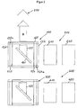
- the printing press has a printing tower 100 with a first printing unit 110 arranged on a support base 600 and a second printing unit 120 arranged above the first printing unit 110, and a substructure 122-125 which forms the second printing unit 120, so that the weight of the second pressure unit 120 rests on the substructure 122-125.
- Each of the printing units 110, 120 has in this embodiment eight printing locations 111 and 121, respectively, wherein two printing locations 111 and 121 are diametrically opposed in the printing unit 110, 120, so that four such pairs 111 and 111 or 121 and 121 of FIG are formed diametrically opposite pressure points. The four pairs are stacked vertically.
- Each printing location 111, 121 comprises a cylinder for printing on a web to be printed and a counter-pressure cylinder for pressing the web to the cylinder for printing, wherein for each pair of diametrically opposed pressure points each of the cylinders for printing on the web of a pressure point Impression cylinder forms for the other pressure point.
- the support base 600 in this embodiment is the floor of a production hall in which the printing press is set up.
- the substructure 122-125 has a vertical portion formed by two vertically spaced and parallel spaced wall members 122, 123 and one Horizontal section, which is formed by two elongated, horizontally arranged support members 124, 125, each with two longitudinal ends.
- the wall members 122, 123 each have a lower end supported on the support base 600, an upper end and two lateral ends.
- the two carrier elements 124, 125 are arranged alongside each other, so that a carrier element 124, 125 connects two opposite, lateral ends of the two wall elements 122, 123 to each other.
- the two longitudinal ends of the support members 124, 125 rest on the upper ends of the wall members 122, 123 so as to be supported thereon.
- the substructure is related to the view of Fig.1 formed portal-shaped and based on the view of Fig.2 box-shaped.
- the first printing unit 110 is arranged between the wall elements 122, 123, wherein the wall elements 122, 123 each have a height dimension between their lower and upper ends (with reference to FIG Fig.1 In other words, the height dimension of the wall members 122, 123 is greater than that of the first printing unit 110 by, for example, 300 mm to 500 mm.
- the carrier elements 124, 125 have between their lateral ends (based on Fig.1 ) or longitudinal ends of a width dimension (based on Fig.1 ) or length dimension, which is slightly larger than the width dimension of the first pressure unit 110 and which extends substantially parallel thereto.
- the length dimension of the carrier elements 124, 125 is, for example 1000 mm to 2000 mm larger than the width dimension of the first printing unit 110.
- the distance at which the carrier elements 124, 125 are arranged alongside one another is slightly less than the depth dimension (based on FIG Fig.1 ) of the second printing unit 120.
- the carrier elements 124, 125 each have an upper surface 124a or 125a, on which the second printing unit 120 is set up.
- the two carrier elements 124, 125 extend horizontally between the first printing unit 110 and the second printing unit 120.
- a first printing web feed device 200 which has two roll changers 210 and 220, is arranged on the support base 600.
- the roll exchangers 210, 220 are pressure roller 211, 212 and 221, 222 can be accommodated.
- the roll changer 210 supplies the first printing unit 110 with a web or printing web 215 to be printed, and the roll changer 220 supplies the second printing unit 120 with a printing web 225.
- the printing web feeding device 200 further has two guide rollers 213 and 214 for guiding the printing web 215 from the first reel splicer 210 to the first printing unit 110 and two guide rollers 223 and 224 for guiding the printing web 225 from the second web changer 220 to the second printing unit 120.
- a second printing tower 300 with a second printing web feed device 400 is arranged parallel to the first printing tower 100 with the first printing web feeding device 200 (or related to Fig.1 in front of these) a second printing tower 300 with a second printing web feed device 400 is arranged.
- the second printing tower 300 and the second printing sheet feeding device are 400 as well as the first printing tower 100 and the first printing web feeding device 200.
- a first web guide 130 is provided between the first printing unit 110 and the second printing unit 120 for insertion and / or removal of a printed or printed web between the first printing unit 110 and the second printing unit 120.
- the first web guide 130 comprises a turning bar 131, which is attached by means of suitable mounting means on the first printing unit 110 to the support members 124, 125 and two guide rollers 132 and 133 which by means of suitable mounting means on the turning bar 131 and under the second Pressure unit 120 are rotatably mounted on the support members 124, 125 are mounted.
- the turning bar 131 is for 90-degree Ausder (in the direction of arrow B in Fig.2 ) of the printing web 215 when it emerges from the first printing unit 110 after printing has taken place.
- the deflecting rollers 132, 133 serve to deflect the printing web 225 into the second printing unit 120.
- the printing web 225 is guided from the second roll changer 220 via the guide rollers 223 and 224 to the second printing unit 120, then deflected via the guide roller 132 into the second printing unit 120 and then passed substantially vertically through the second printing unit 120 ,
- a printing web 415 from the adjacent, second printing tower 300 are passed.
- This printing web 415 is the printing web which is at 90 Degrees from the same floor to the first printing unit 110 arranged printing unit of the second printing tower 300 can be used.
- the first web guide 130 for the passable printing web 415 additionally has a web securing device with a web tension control device and a register control device.
- the railway securing device is likewise mounted on the carrier elements 124, 125 by means of suitable mounting means.
- a second web guide 140 integrated for passing at least one printing web through the wall element 123.
- the second web guide 140 has two pairs of rollers 141 and 142, wherein each pair of two rollers are each pressing against each other and arranged the printing web between them pressing rollers can be guided vertically upwards.
- a guide roller 143 is arranged, via which a printing web 245 of another reel changer 240 than the second reel 220 from in the second web guide 140 and then via the guide roller 133 of the first web guide 130 into the second printing unit 120 is feasible.
- a third web guide 150 is provided below the first printing unit 110 for inserting or removing a printing web 215 into and out of the first printing unit 110.
- the third web guide 150 has a deflection roller 151 for deflecting the printing web 215 into the first printing unit 110.
- the printing web 215 When the printing web 215 emerges from the top of the first printing unit 110, the printing web 215 is guided over the turning bar 131, whereby the printing web 215 is rotated by 90 degrees about its longitudinal axis and turned to the horizontal, so that the printing web in the direction of arrow B in Fig.2 running.
- a fourth web guide 160 is provided above the second printing unit 120, which in this embodiment is the uppermost printing unit, for inserting or removing a printing web at least into and out of the second printing unit 120.
- the fourth web guide 160 has a turning bar 161 for 90-degree turning (in the direction of the arrow B in FIG Fig.2 ) of the printing web 225 when it emerges from the second printing unit 120 after printing has taken place.
- the printing press further comprises a folding device 500.
- the folding device 500 has a former (normal hopper) for folding the printing web 215 of the first printing unit 110 and a former (hopper) for folding the printing web 225 of the second printing unit 120.
- the printing web 415 of the adjacent second printing tower 300 can be passed between the first printing unit 110 and the second printing unit 120 of the first printing tower 100 and then fed to the folding device 500, for example for folding.
- the printing tower 100 can be increased as required by arranging an additional substructure on the substructure 122-125 on which additional substructure a further printing unit can be mounted.
- Such an accessory subassembly may be the same as the subassembly 122-125, or may be modified as needed.
- the second embodiment of the first embodiment is similar except that the printing tower 100 above the second printing unit 120 includes a third printing unit 170 and an auxiliary subassembly 172-175 that supports the third printing unit 170 so that the weight of the third Pressure unit 170 on the additional substructure 172-175 loads.
- the sub-base assembly 172-175 which is the same as the sub-assembly 122-125 of the first and second pressure units 110, 120, is supported on the sub-assembly 122-125.
- the third printing unit 170 is set up on the surface 174a, 175a formed by the support elements 174, 175 of the additional substructure 172-175.
- the fourth web guide 160 has according to the second embodiment, a turning bar 161 which is attached by means of suitable mounting means on the second printing unit 120 to the support members 174, 175, and two guide rollers 162 and 163, by means of suitable mounting means on the turning bar 161 and below third printing unit 170 are rotatably mounted on the support members 174, 175 are mounted.
- the turning bar 161 is for 90-degree Ausder (in the direction of arrow B in Fig.2 ) of the printing web 225 when it emerges from the second printing unit 120 after printing has taken place.
- the guide rollers 162, 163 serve to deflect a printing web 235 provided by a third reel changer 230 into the third printing unit 170.
- the printing web 235 is guided from the third roll changer 230 (not shown) via deflecting rollers 233 (not shown) and 234 to the third printing unit 170, then deflected via the deflecting roller 162 into the third printing unit 170 and then in Substantially passed vertically through the third printing unit 170.
- a printing web 425 of the adjacent second printing tower 300 are passed.
- This printing web 425 is the printing web which can be used at 90 degrees from the printing unit of the second printing tower 300 which is arranged at the same level as the second printing unit 120.
- the fourth web guide 160 for the passable printing web 425 additionally has a web securing device with a web tension control device and a register control device.
- the railway securing device is likewise mounted on the carrier elements 174, 175 by means of suitable mounting means,
- a fifth web guide 180 is provided above the third printing unit 170, which is the uppermost printing unit in this second embodiment, for inserting or feeding out a printing web into and out of the third and uppermost printing units 170, respectively.
- the fifth web guide 180 has a turning bar 181 for 90-degree turning (in the direction of the arrow B in FIG Fig.2 ) of the printing web 235 when it emerges from the third printing unit 170 after printing has taken place.
- the printing press has the folding device 500 and the printing web 425 of the adjacent second printing tower 300 between the second printing unit 120 and the third printing unit 170 of the first printing tower 100 can be passed and then fed, for example, for folding the folding device 500 become.
- the printing tower 100 can be increased as required by a further additional sub-assembly is disposed on the additional substructure 172-175, on which additional sub-subassembly another print unit can be mounted.
- this additional sub-assembly may be the same as the sub-assembly 122-125, or may be modified as needed.
Landscapes
- Engineering & Computer Science (AREA)
- Mechanical Engineering (AREA)
- Rotary Presses (AREA)
Applications Claiming Priority (1)
| Application Number | Priority Date | Filing Date | Title |
|---|---|---|---|
| DE102007025499A DE102007025499A1 (de) | 2007-06-01 | 2007-06-01 | Rotationsdruckmaschine |
Publications (2)
| Publication Number | Publication Date |
|---|---|
| EP1997629A2 true EP1997629A2 (fr) | 2008-12-03 |
| EP1997629A3 EP1997629A3 (fr) | 2010-10-06 |
Family
ID=39708616
Family Applications (1)
| Application Number | Title | Priority Date | Filing Date |
|---|---|---|---|
| EP08009612A Withdrawn EP1997629A3 (fr) | 2007-06-01 | 2008-05-27 | Presse rotative |
Country Status (5)
| Country | Link |
|---|---|
| US (1) | US20080295714A1 (fr) |
| EP (1) | EP1997629A3 (fr) |
| JP (1) | JP3144034U (fr) |
| CN (1) | CN201283689Y (fr) |
| DE (1) | DE102007025499A1 (fr) |
Families Citing this family (2)
| Publication number | Priority date | Publication date | Assignee | Title |
|---|---|---|---|---|
| DE102010002613A1 (de) * | 2010-03-05 | 2011-09-08 | Koenig & Bauer Aktiengesellschaft | Druckturm einer Druckmaschine und ein Verfahren zur Bereitstellung einer Standfläche eines Druckturms einer Druckmaschine |
| DE102017215062B3 (de) | 2017-08-29 | 2018-05-30 | Koenig & Bauer Ag | Vorrichtung zur Vermeidung von Resonanzschwingungen in Drucktürmen sowie Druckmaschine mit einer solchen Vorrichtung |
Family Cites Families (9)
| Publication number | Priority date | Publication date | Assignee | Title |
|---|---|---|---|---|
| DE2924591A1 (de) * | 1979-06-19 | 1981-01-22 | Maschf Augsburg Nuernberg Ag | Unterbau fuer eine rollen-rotationsdruckmaschine |
| DE4327278C5 (de) * | 1993-08-13 | 2005-09-22 | Maschinenfabrik Wifag | Traggestell für eine Rollenrotationsdruckmaschine |
| JP2927782B1 (ja) * | 1998-07-23 | 1999-07-28 | 株式会社東京機械製作所 | 紙しわ防止装置 |
| DE19833470C2 (de) * | 1998-07-24 | 2000-05-18 | Koenig & Bauer Ag | Druckeinheit |
| DE10008220A1 (de) * | 2000-02-23 | 2001-08-30 | Roland Man Druckmasch | Gestell eines Druckwerkes |
| US6748859B2 (en) * | 2002-09-09 | 2004-06-15 | Delaware Capital Formation, Inc. | Separable printing press ink cassette assembly and method |
| ATE384618T1 (de) * | 2003-04-23 | 2008-02-15 | Koenig & Bauer Ag | Rollenrotationsdruckmaschine |
| DE202006019945U1 (de) * | 2006-05-31 | 2007-07-19 | Man Roland Druckmaschinen Ag | Rollenrotationsdruckmaschine |
| DE102006030457A1 (de) * | 2006-07-01 | 2008-01-03 | Man Roland Druckmaschinen Ag | Druckeinheit einer Rollenrotationsdruckmaschine |
-
2007
- 2007-06-01 DE DE102007025499A patent/DE102007025499A1/de not_active Withdrawn
-
2008
- 2008-05-27 EP EP08009612A patent/EP1997629A3/fr not_active Withdrawn
- 2008-05-30 CN CNU2008201198359U patent/CN201283689Y/zh not_active Expired - Fee Related
- 2008-05-30 US US12/130,712 patent/US20080295714A1/en not_active Abandoned
- 2008-06-02 JP JP2008003662U patent/JP3144034U/ja not_active Expired - Fee Related
Also Published As
| Publication number | Publication date |
|---|---|
| US20080295714A1 (en) | 2008-12-04 |
| EP1997629A3 (fr) | 2010-10-06 |
| JP3144034U (ja) | 2008-08-14 |
| DE102007025499A1 (de) | 2008-12-04 |
| CN201283689Y (zh) | 2009-08-05 |
Similar Documents
| Publication | Publication Date | Title |
|---|---|---|
| EP0638419B2 (fr) | Cadre porteur pour une presse rotative à bobines | |
| EP1265803A1 (fr) | Dispositif de barres de retournement et procede de deviation d'une bande de materiau | |
| EP0047909B1 (fr) | Groupe imprimante pour une rotative d'impression sur bandes | |
| EP1528982A1 (fr) | Machines d'impression a plusieurs groupes d'impression | |
| EP1106555A2 (fr) | Appareil pour le guidage de bandes de matériau dans presses rotatives d'impression | |
| DE102006002304A1 (de) | Bogendruckmaschine | |
| DE112009002489T5 (de) | Druckmaschine und Druckgruppe für formatvariablen Offset | |
| DE102006061452A1 (de) | Druckplattenkassette | |
| EP1456107A1 (fr) | Dispositif de production de produits plies | |
| EP1997629A2 (fr) | Presse rotative | |
| EP0053226A1 (fr) | Groupe imprimante pour une rotative d'impression sur bandes | |
| CH695766A5 (de) | Rotationsdruckmaschine mit Bebilderungsvorrichtung. | |
| EP1767354A2 (fr) | Unité d'impression | |
| DE102004051263A1 (de) | Druckmaschinenanordnung | |
| EP1140498A2 (fr) | Rotative a bobines | |
| DE102008035677B4 (de) | Druckeinheit für eine Rollenrotationsdruckmaschine | |
| DE102012013002A1 (de) | Rollendruckmaschine | |
| DE10163211C2 (de) | Vorrichtung zur Herstellung von Falzprodukten | |
| EP1832420A2 (fr) | Dispositif de pliagede doté d'appareils de pliage à différentes hauteurs | |
| EP1140500A1 (fr) | Rotative a bobines | |
| DE102007002495B4 (de) | Rollenrotationsdruckmaschine zum zweiseitigen Bedrucken einer Bedruckstoffbahn | |
| WO2003084751A1 (fr) | Unites d'impression | |
| DE102006058196B4 (de) | Druckmaschinenanlage | |
| EP2052858A2 (fr) | Agencement de presse d'impression | |
| DE102004008770B4 (de) | Rollenrotationsdruckmaschine |
Legal Events
| Date | Code | Title | Description |
|---|---|---|---|
| PUAI | Public reference made under article 153(3) epc to a published international application that has entered the european phase |
Free format text: ORIGINAL CODE: 0009012 |
|
| AK | Designated contracting states |
Kind code of ref document: A2 Designated state(s): AT BE BG CH CY CZ DE DK EE ES FI FR GB GR HR HU IE IS IT LI LT LU LV MC MT NL NO PL PT RO SE SI SK TR |
|
| AX | Request for extension of the european patent |
Extension state: AL BA MK RS |
|
| PUAL | Search report despatched |
Free format text: ORIGINAL CODE: 0009013 |
|
| AK | Designated contracting states |
Kind code of ref document: A3 Designated state(s): AT BE BG CH CY CZ DE DK EE ES FI FR GB GR HR HU IE IS IT LI LT LU LV MC MT NL NO PL PT RO SE SI SK TR |
|
| AX | Request for extension of the european patent |
Extension state: AL BA MK RS |
|
| 17P | Request for examination filed |
Effective date: 20110323 |
|
| AKX | Designation fees paid |
Designated state(s): CH DE FR GB LI |
|
| 19U | Interruption of proceedings before grant |
Effective date: 20120201 |
|
| 19W | Proceedings resumed before grant after interruption of proceedings |
Effective date: 20140203 |
|
| STAA | Information on the status of an ep patent application or granted ep patent |
Free format text: STATUS: THE APPLICATION HAS BEEN WITHDRAWN |
|
| 18W | Application withdrawn |
Effective date: 20140311 |