EP2052858A2 - Agencement de presse d'impression - Google Patents
Agencement de presse d'impression Download PDFInfo
- Publication number
- EP2052858A2 EP2052858A2 EP08018614A EP08018614A EP2052858A2 EP 2052858 A2 EP2052858 A2 EP 2052858A2 EP 08018614 A EP08018614 A EP 08018614A EP 08018614 A EP08018614 A EP 08018614A EP 2052858 A2 EP2052858 A2 EP 2052858A2
- Authority
- EP
- European Patent Office
- Prior art keywords
- printing
- printing units
- units
- juxtaposed
- arrangement according
- Prior art date
- Legal status (The legal status is an assumption and is not a legal conclusion. Google has not performed a legal analysis and makes no representation as to the accuracy of the status listed.)
- Withdrawn
Links
Images


Classifications
-
- B—PERFORMING OPERATIONS; TRANSPORTING
- B41—PRINTING; LINING MACHINES; TYPEWRITERS; STAMPS
- B41F—PRINTING MACHINES OR PRESSES
- B41F13/00—Common details of rotary presses or machines
- B41F13/0024—Frames
-
- B—PERFORMING OPERATIONS; TRANSPORTING
- B41—PRINTING; LINING MACHINES; TYPEWRITERS; STAMPS
- B41F—PRINTING MACHINES OR PRESSES
- B41F7/00—Rotary lithographic machines
- B41F7/02—Rotary lithographic machines for offset printing
Definitions
- the invention relates to a printing press arrangement according to the preamble of claim 1.
- the present invention has the object to provide a novel printing machine arrangement.
- all the roll changers and all printing units are arranged in one plane in a matrix-like or array-like manner while minimizing the distance between roll changers positioned side by side and minimizing at least the distance between juxtaposed printing units serving the printing of different printing substrate webs.
- all reel changers and all printing units are arranged in a matrix-like or matrix-like manner, while minimizing the distance between juxtaposed roll changers, while minimizing the distance between juxtaposed printing units serving different printing substrate webs and preferably minimizing the spacing between successively positioned, the same printing substrate serving printing units.
- a space minimization can be ensured
- all reel changers and printing units are accessible from a single operating level, so it is not necessary to hold several vertically superimposed operating levels or gallery levels. This makes the operation of printing machines more ergonomic.
- the present invention relates to a printing machine arrangement having a plurality of reel changers, a plurality of printing units and at least one folding apparatus.
- Fig. 1 shows a schematic representation of a first embodiment of a printing press arrangement according to the invention in side view, wherein in Fig. 1 a reel changer 10, two printing units 11, 12 and a folding apparatus 13 are visible.
- the roll changer 10, the two printing units 11, 12 and the folder 13 are positioned one behind the other, with the printing units 11, 12 positioned one behind the other serving for printing one and the same printing material web 14 which is removed from a printing material roll in the area of the roll changer 10.
- a printing press arrangement not only has printing units 11, 12 positioned behind one another, serving for printing the same printing substrate web, but also juxtaposed printing units, printing units positioned next to one another serving to print different printing substrate webs.
- a printing press arrangement comprises a plurality of reel splicers and a plurality of printing units, wherein the printing units are arranged in an array-like or matrix-like manner one after the other and next to each other.
- the printing material webs printed in the printing units positioned side by side and in succession can either be fed to a single folder or to a plurality of folders.
- all reel changers 10 and all printing units 11, 12 are arranged in a matrix-like or array-like manner, minimizing the distance between them.
- juxtaposed roll changers 10 are positioned minimizing the distance therebetween.
- juxtaposed printing units serving for printing different printing material webs are arranged while minimizing the distance between them.
- successively arranged printing units serving for printing the same printing material web are arranged with minimization of the distance from each other.
- All reel changer 10 and printing units 11, 12 are thus arranged in a matrix-like and array-like manner in a plane, wherein the distance between juxtaposed and successively positioned printing units and reel splitter is minimized.
- Each printing unit 11, 12 has in the embodiment shown a maximum of four printing units 15, wherein each printing unit 15 comprises a forme cylinder 16, a transfer cylinder 17, a non-illustrated inking unit and optionally a non-illustrated dampening unit.
- the printing units 11, 12 are according to Fig. 1 formed as so-called 9-cylinder satellite printing units, all transfer cylinders 17 of the four printing units 15 of a printing unit 11 and 12 roll accordingly on a common satellite cylinder 18 from.
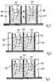
- Fig. 2 to 4 show three different possible embodiments of two juxtaposed, the printing of different printing material webs serving printing units 11th
- each printing unit 11 has two separate side walls 19, wherein according to Fig. 2 adjacent, immediately opposite side walls 19 are positioned with minimal distance from each other, and wherein spaced apart side walls 19 of the two printing units 11 for each printing unit 11 are each assigned separate drives 20 to drive the printing units 15 of both printing units 11 separately and therefore independently.
- Fig. 3 is the two juxtaposed, the printing of different printing material webs serving printing units 11 associated with a common, central side wall 21 and spaced apart, separate side walls 22, wherein the spaced apart, separate side walls 22 in turn in accordance with Fig. 2 separate drives 20 are assigned for each printing unit to drive the printing units of both printing units 11 separately and therefore independently of each other.
- a side wall can be saved, whereby the space required for juxtaposed, the printing of different printing material webs serving pressure units reduced.
- Fig. 4 shows a further possible embodiment of two side by side positioned, the printing of different printing substrate webs serving printing units 11, wherein in Fig. 4 in accordance to Fig. 3 two pressure units 11 a common, central side wall 21 is assigned, but in contrast to Fig. 3 Only one of the two separate side walls 22 of the two printing unit 11 drives 23 are assigned, which serve the common driving of the printing units of both printing units 11. In Fig. 4 can therefore continue to be reduced space, but the printing units both positioned next to each other, the printing of different printing material webs serving printing units 11 only together and thus can be driven synchronously.
- the printing units of juxtaposed printing units 11, which serve the printing of different printing material webs, can all be configured as 312 printing units or all as 4/2 printing units or all as 6/2 printing units, wherein the first number is the number of in the axial direction of the Form cylinder 16 juxtaposed printing plates and the second number indicates the number of circumferentially of the forme cylinder 16 successively positioned printing plates per printing unit.
- the printing units of the juxtaposed printing units 11, which serve the printing of different printing material webs, can also all be 3/1 or all 4/1 or all 5/1 or all 5/2 or all be designed as 6/1 printing units.
- all printing units of one of the two juxtaposed printing units are designed as 6/2 printing units, whereas all the printing units of the other of the two juxtaposed printing units 11 as 5/2 printing units or as 4/2 printing units or as 312 Printing units or as 2/2 printing units are formed. It is also possible that all printing units of one of the two juxtaposed printing units are designed as 6/1 printing units, whereas all printing units of the other of the two juxtaposed printing units 11 as 5/1 printing units or as 4/1 printing units or as 3rd / 1-printing units or as 2/1-printing units are formed.
- the printing units of one of the two juxtaposed printing units are designed as 4/2 printing units and the printing units of the other of the two juxtaposed printing units 11 as 3/2 printing units or as 2/2 printing units. It is also possible that all printing units of one of the two juxtaposed printing units are formed as 4/1 printing units, whereas all the printing units of the other of the two juxtaposed printing units 11 are formed as 3/1 printing units or as 2/1 printing units.
- the printing units of one of the two juxtaposed printing units are designed as 3/2 printing units and the printing units of the other of the two juxtaposed printing units 11 as 2/2 printing units.
- all printing units of one of the two juxtaposed printing units are designed as 3/1 printing units, whereas all the printing units of the other of the two juxtaposed printing units 11 are formed as 2/1 printing units.
- Fig. 5 shows a variant of the present invention, in which the printing units 11, 12 are formed as so-called 90-cylinder satellite printing units, in which therefore the transfer cylinder 17 of each two printing units 15 roll on a common satellite cylinder 18.
- a modularization of the printing units 11, 12 is proposed such that a first module of the printing units 11, 12, the transfer cylinder 17 and the satellite cylinder 18 are assigned, whereas a second module of the printing units 11, 12, the forme cylinder 16, the inking units and optionally the dampening units assigned.
- This modularization makes it possible to separate the cylinders assigned to the individual modules for maintenance work.
- all the roll changers, printing units and folders are arranged in an array-like or matrix-like manner in only one single plane.
- Particularly preferred is an embodiment in which the printing units of juxtaposed printing units that serve the printing of different printing material webs are driven by common drives (see Fig. 4 ).
- Fig. 4 can then if z. B. the printing units 15 of the juxtaposed printing units 11 are formed as 3/2 printing units, a total of both printing units 11 a 6/2 pressure are provided, while avoiding process engineering problems of long and slender cylinders.
- the arrangement according to the invention in particular the formation of so-called hot spots and the formation of a so-called fan out can be avoided.
Landscapes
- Engineering & Computer Science (AREA)
- Mechanical Engineering (AREA)
- Rotary Presses (AREA)
Applications Claiming Priority (1)
| Application Number | Priority Date | Filing Date | Title |
|---|---|---|---|
| DE200710050978 DE102007050978A1 (de) | 2007-10-25 | 2007-10-25 | Druckmaschinenanordnung |
Publications (2)
| Publication Number | Publication Date |
|---|---|
| EP2052858A2 true EP2052858A2 (fr) | 2009-04-29 |
| EP2052858A3 EP2052858A3 (fr) | 2012-04-04 |
Family
ID=40347873
Family Applications (1)
| Application Number | Title | Priority Date | Filing Date |
|---|---|---|---|
| EP08018614A Withdrawn EP2052858A3 (fr) | 2007-10-25 | 2008-10-24 | Agencement de presse d'impression |
Country Status (2)
| Country | Link |
|---|---|
| EP (1) | EP2052858A3 (fr) |
| DE (1) | DE102007050978A1 (fr) |
Families Citing this family (1)
| Publication number | Priority date | Publication date | Assignee | Title |
|---|---|---|---|---|
| DE102016124332A1 (de) | 2016-12-14 | 2018-06-14 | Manroland Web Systems Gmbh | Rotationsdruckmaschine |
Family Cites Families (14)
| Publication number | Priority date | Publication date | Assignee | Title |
|---|---|---|---|---|
| DE184566C (fr) * | 1905-08-22 | |||
| DE198806C (de) * | 1905-08-22 | 1908-05-26 | Duplex Printing Press Co | Mehrrollenrotationsdruckpresse |
| US1108162A (en) * | 1913-08-18 | 1914-08-25 | Goss Printing Press Co Ltd | Printing-press. |
| US1197876A (en) * | 1915-09-27 | 1916-09-12 | Goss Printing Press Co Ltd | Printing-press. |
| US1229610A (en) * | 1916-05-11 | 1917-06-12 | John R Hays | Printing-press. |
| GB111424A (en) * | 1917-04-24 | 1917-11-29 | John Ruth Hays | Improvements in or relating to Rotary Printing Presses. |
| US1924584A (en) * | 1926-02-18 | 1933-08-29 | Wood Newspaper Mach Corp | Press unit drive |
| JP2000168035A (ja) * | 1998-12-11 | 2000-06-20 | Toshiba Mach Co Ltd | 複合型印刷装置 |
| DE502004009017D1 (de) * | 2003-07-11 | 2009-04-02 | Koenig & Bauer Ag | Rollenrotationsdruckmaschine |
| JP4659363B2 (ja) * | 2004-01-05 | 2011-03-30 | 株式会社ミヤコシ | マルチウエブ型輪転機 |
| DE102004051263A1 (de) * | 2004-10-21 | 2006-04-27 | Man Roland Druckmaschinen Ag | Druckmaschinenanordnung |
| DE102005037731B4 (de) * | 2005-04-19 | 2009-06-04 | Koenig & Bauer Aktiengesellschaft | Druckmaschinenanlagen |
| DE102005036450B3 (de) * | 2005-05-13 | 2006-12-21 | Koenig & Bauer Ag | Druckmaschine |
| DE102007031762C5 (de) * | 2007-07-07 | 2016-12-29 | Koenig & Bauer Ag | Rotationsdruckmaschine |
-
2007
- 2007-10-25 DE DE200710050978 patent/DE102007050978A1/de not_active Withdrawn
-
2008
- 2008-10-24 EP EP08018614A patent/EP2052858A3/fr not_active Withdrawn
Also Published As
| Publication number | Publication date |
|---|---|
| EP2052858A3 (fr) | 2012-04-04 |
| DE102007050978A1 (de) | 2009-04-30 |
Similar Documents
| Publication | Publication Date | Title |
|---|---|---|
| DE102007035689B3 (de) | Verfahren zum Anordnen von Druckformen auf einem Formzylinder einer Druckmaschine | |
| DE102006061452A1 (de) | Druckplattenkassette | |
| EP1683634B1 (fr) | Machine d'impression rotative | |
| EP1226937B1 (fr) | Entraînement sans arbre à moteur pour une machine d'impression avec un rouleau d'encrage anilox | |
| EP2052858A2 (fr) | Agencement de presse d'impression | |
| DE202005010058U1 (de) | Rollenrotationsdruckmaschine | |
| EP1650027A2 (fr) | Arrangement d'unités de changeur de rouleaux dans une machine d'impression | |
| DE19822892A1 (de) | Druckmaschine | |
| EP1767354A2 (fr) | Unité d'impression | |
| DE102016201747A1 (de) | Verfahren zum registergenauen Bearbeiten einer Bahn | |
| DE102007046163B4 (de) | Druckeinheit für eine Rotationsdruckmaschine | |
| EP1140498A2 (fr) | Rotative a bobines | |
| DE102008035677B4 (de) | Druckeinheit für eine Rollenrotationsdruckmaschine | |
| DE10321989B4 (de) | Druckmaschine | |
| EP2296885A1 (fr) | Machine d'impression à plusieurs dispositifs d'encrage | |
| DE102019120263A1 (de) | Druckwerk einer Rotationsdruckmaschine | |
| EP1712355B2 (fr) | Unité d'impression d'une machine rotative d'impression | |
| EP1997629A2 (fr) | Presse rotative | |
| WO2005016646A1 (fr) | Rotative offset a bobines pourvue d'une pluralite de mecanismes d'impression comportant des cylindres porte-cliches et de transfert pour l'impression recto-verso | |
| EP1712354B1 (fr) | Unité d'impression d'une presse rotative | |
| EP2147787B1 (fr) | Unité d'impression d'une presse rotative | |
| DE102004011070B4 (de) | Ausbaubare Druckeinheit für Rollen-Offsetdruckmaschinen | |
| DE102023134218A1 (de) | Verfahren zum Betreiben einer Druckeinheit | |
| EP1733879B1 (fr) | Machine d'impression rotative à bobines et procédé de fabrication de plaques d'impression pour une telle machine | |
| DE102006008303B3 (de) | Rotationsdruckmaschine |
Legal Events
| Date | Code | Title | Description |
|---|---|---|---|
| PUAI | Public reference made under article 153(3) epc to a published international application that has entered the european phase |
Free format text: ORIGINAL CODE: 0009012 |
|
| AK | Designated contracting states |
Kind code of ref document: A2 Designated state(s): AT BE BG CH CY CZ DE DK EE ES FI FR GB GR HR HU IE IS IT LI LT LU LV MC MT NL NO PL PT RO SE SI SK TR |
|
| AX | Request for extension of the european patent |
Extension state: AL BA MK RS |
|
| PUAL | Search report despatched |
Free format text: ORIGINAL CODE: 0009013 |
|
| 19U | Interruption of proceedings before grant |
Effective date: 20120201 |
|
| AK | Designated contracting states |
Kind code of ref document: A3 Designated state(s): AT BE BG CH CY CZ DE DK EE ES FI FR GB GR HR HU IE IS IT LI LT LU LV MC MT NL NO PL PT RO SE SI SK TR |
|
| AX | Request for extension of the european patent |
Extension state: AL BA MK RS |
|
| RIC1 | Information provided on ipc code assigned before grant |
Ipc: B41F 7/02 20060101ALI20120301BHEP Ipc: B41F 13/00 20060101AFI20120301BHEP |
|
| 19W | Proceedings resumed before grant after interruption of proceedings |
Effective date: 20140203 |
|
| STAA | Information on the status of an ep patent application or granted ep patent |
Free format text: STATUS: THE APPLICATION HAS BEEN WITHDRAWN |
|
| 18W | Application withdrawn |
Effective date: 20140311 |