EP2000316B1 - Procédé de fabrication d'un support et support - Google Patents
Procédé de fabrication d'un support et support Download PDFInfo
- Publication number
- EP2000316B1 EP2000316B1 EP08010099A EP08010099A EP2000316B1 EP 2000316 B1 EP2000316 B1 EP 2000316B1 EP 08010099 A EP08010099 A EP 08010099A EP 08010099 A EP08010099 A EP 08010099A EP 2000316 B1 EP2000316 B1 EP 2000316B1
- Authority
- EP
- European Patent Office
- Prior art keywords
- modules
- support
- longitudinal direction
- carrier
- another
- Prior art date
- Legal status (The legal status is an assumption and is not a legal conclusion. Google has not performed a legal analysis and makes no representation as to the accuracy of the status listed.)
- Not-in-force
Links
- 238000000034 method Methods 0.000 title claims description 12
- 238000004519 manufacturing process Methods 0.000 title description 13
- 238000003754 machining Methods 0.000 claims description 8
- 239000000463 material Substances 0.000 claims description 7
- OKTJSMMVPCPJKN-UHFFFAOYSA-N Carbon Chemical compound [C] OKTJSMMVPCPJKN-UHFFFAOYSA-N 0.000 claims 1
- 229910052799 carbon Inorganic materials 0.000 claims 1
- 229910000831 Steel Inorganic materials 0.000 description 4
- 238000005452 bending Methods 0.000 description 4
- 229910052751 metal Inorganic materials 0.000 description 4
- 239000002184 metal Substances 0.000 description 4
- 239000010959 steel Substances 0.000 description 4
- 229920000049 Carbon (fiber) Polymers 0.000 description 3
- 239000004917 carbon fiber Substances 0.000 description 3
- 239000000969 carrier Substances 0.000 description 3
- 238000007639 printing Methods 0.000 description 3
- 238000004026 adhesive bonding Methods 0.000 description 2
- 238000005520 cutting process Methods 0.000 description 2
- 238000005304 joining Methods 0.000 description 2
- 239000006223 plastic coating Substances 0.000 description 2
- 238000003466 welding Methods 0.000 description 2
- 239000000853 adhesive Substances 0.000 description 1
- 230000001070 adhesive effect Effects 0.000 description 1
- 229910052782 aluminium Inorganic materials 0.000 description 1
- XAGFODPZIPBFFR-UHFFFAOYSA-N aluminium Chemical compound [Al] XAGFODPZIPBFFR-UHFFFAOYSA-N 0.000 description 1
- 239000011248 coating agent Substances 0.000 description 1
- 238000000576 coating method Methods 0.000 description 1
- 239000002131 composite material Substances 0.000 description 1
- 238000005260 corrosion Methods 0.000 description 1
- 230000007797 corrosion Effects 0.000 description 1
- 238000007598 dipping method Methods 0.000 description 1
- 238000001125 extrusion Methods 0.000 description 1
- 239000003292 glue Substances 0.000 description 1
- 238000010438 heat treatment Methods 0.000 description 1
- 238000003384 imaging method Methods 0.000 description 1
- 238000003698 laser cutting Methods 0.000 description 1
- 230000013011 mating Effects 0.000 description 1
- 238000005058 metal casting Methods 0.000 description 1
- VNWKTOKETHGBQD-UHFFFAOYSA-N methane Chemical compound C VNWKTOKETHGBQD-UHFFFAOYSA-N 0.000 description 1
- 229910000679 solder Inorganic materials 0.000 description 1
- 239000007787 solid Substances 0.000 description 1
- 125000006850 spacer group Chemical group 0.000 description 1
- 238000005507 spraying Methods 0.000 description 1
Images

Classifications
-
- B—PERFORMING OPERATIONS; TRANSPORTING
- B41—PRINTING; LINING MACHINES; TYPEWRITERS; STAMPS
- B41J—TYPEWRITERS; SELECTIVE PRINTING MECHANISMS, i.e. MECHANISMS PRINTING OTHERWISE THAN FROM A FORME; CORRECTION OF TYPOGRAPHICAL ERRORS
- B41J23/00—Power drives for actions or mechanisms
-
- B—PERFORMING OPERATIONS; TRANSPORTING
- B41—PRINTING; LINING MACHINES; TYPEWRITERS; STAMPS
- B41J—TYPEWRITERS; SELECTIVE PRINTING MECHANISMS, i.e. MECHANISMS PRINTING OTHERWISE THAN FROM A FORME; CORRECTION OF TYPOGRAPHICAL ERRORS
- B41J25/00—Actions or mechanisms not otherwise provided for
- B41J25/304—Bodily-movable mechanisms for print heads or carriages movable towards or from paper surface
-
- B—PERFORMING OPERATIONS; TRANSPORTING
- B41—PRINTING; LINING MACHINES; TYPEWRITERS; STAMPS
- B41J—TYPEWRITERS; SELECTIVE PRINTING MECHANISMS, i.e. MECHANISMS PRINTING OTHERWISE THAN FROM A FORME; CORRECTION OF TYPOGRAPHICAL ERRORS
- B41J29/00—Details of, or accessories for, typewriters or selective printing mechanisms not otherwise provided for
- B41J29/02—Framework
-
- Y—GENERAL TAGGING OF NEW TECHNOLOGICAL DEVELOPMENTS; GENERAL TAGGING OF CROSS-SECTIONAL TECHNOLOGIES SPANNING OVER SEVERAL SECTIONS OF THE IPC; TECHNICAL SUBJECTS COVERED BY FORMER USPC CROSS-REFERENCE ART COLLECTIONS [XRACs] AND DIGESTS
- Y10—TECHNICAL SUBJECTS COVERED BY FORMER USPC
- Y10T—TECHNICAL SUBJECTS COVERED BY FORMER US CLASSIFICATION
- Y10T29/00—Metal working
- Y10T29/49—Method of mechanical manufacture
- Y10T29/49826—Assembling or joining
Definitions
- the invention relates to a method for producing a carrier designed as a prismatic hollow body whose walls are formed by joining each in the longitudinal direction of the carrier successively arranged Obergurtmodulen, Untergurtmodulen, front wall modules and backplane modules, wherein in the interior of the carrier at intervals transverse webs are arranged and wherein the carrier at least one guideway running in its longitudinal direction is arranged for an assembly movable along the guideway.
- the document US 2007/0000886 A1 discloses a method for manufacturing a machine bed for a machine tool, wherein to shorten the manufacturing time, the machine bed is made of a plate material which is patterned by means of laser processing or cutting machines.
- the machine bed is made of a plate material which is patterned by means of laser processing or cutting machines.
- the document GB 2 387 816 A discloses a scanning device for a printer, the scanning device comprising first and second webs which are held by one or more support means.
- the print image to be applied is applied in a plurality of processes, with only one partial print taking place at a time.
- the scanning device in particular the first and second webs, are arranged rigidly relative to one another on the support means in order to double the print throughput by arranging two print heads.
- each track comprises a rail support means for each two or more rails which are mounted on the rail support means.
- each frame member has an alignment point for accurately aligning a rail of a web with respect to the frame.
- the webs are adjustably fixed to the frame part, thus an exact alignment of the two webs to each other is possible after the webs are arranged on the frame part, whereby the two webs are kept exactly parallel to each other. Furthermore, the first and second web each protrude beyond this at different ends of the frame part in order to be able to arrange, for example, a service station in order to be able to wait or exchange the print head.
- the rail support means is machined to have a tolerance of less than 0.1 mm per meter. From this support means now the rails are held and fixed by means of screws with this, so as to compensate for any nonlinearity of the rail.
- a first rail is received by the V-shaped rail receiving means and bolted thereto.
- a reference spacer means is inserted in the web or between the rails, so as to be able to align and fix the second web correctly.
- the document DE 101 05 001 A1 discloses a printer chassis for holding a imaging drum comprising a sheet metal frame which is defined by a plurality of in Is formed engaging one another rigid elements, which are firmly connected by means of a plastic coating.
- the sheet metal parts are cut so that they form rigid elements, which are provided with projections and slots, can engage in the other rigid elements, so that they form the sheet metal frame of the chassis and in particular can be quickly assembled by hand.
- the assembled structure is then coated by dipping or spraying with a plastic to make a solid chassis.
- the plastic coating creates a seal which adheres to the mating elements and holds them in place at the protrusions and slots.
- this chassis is easy to manufacture and at the same time structurally sufficiently strong and thus forms a suitable replacement for a metal casting or a welded part in some applications.
- the individual elements are engaged with each other, fixed in a fixed spatial relationship and protected against corrosion.
- the document DE 699 26 723 T2 discloses a printer chassis assembly that permits precise positioning of components while still allowing wide design flexibility in positioning and mounting other components.
- the chassis has a first structural support for supporting a slide bar means for a print carriage and two structural side panel members each defining a seat for the slide bar means.
- the first carrier is attached to each side plate member by means of a plurality of attachment points such that deformation of the first carrier is prevented during attachment of the further structure carrier or during use of the printer.
- the gantry has sleeve supports adapted for positioning a front and rear precision steel bar with the carriage moving on these precision steel bars. Since these steel bars are not exactly straight in practice, it is necessary to straighten them by holding them firmly against the precisely shaped carrier, without affecting a thermally induced longitudinal movement. In the center of the bar and the carrier a firm and accurate positioning of the bar is achieved, to the ends of the bar and the carrier is the Aperture, however, elongated, whereby the rod can perform thermal movements along its longitudinal extent. Overall, three apertures are provided along a rod. Since the main beams define the rigidity of the chassis, and in particular are made of extruded aluminum, thermal expansion problems can be avoided and further machining to achieve a corresponding accuracy is possible. However, it is contemplated to mechanically post-process a support for stably supporting a flat printing plate so as to obtain flow-tightness to hold paper tightly against the disk by means of negative pressure.
- the object of the present invention is to propose a method for producing a modular generic carrier whose at least one guideway has an increased precision compared with the guideways of known carriers, which is furthermore independent of the manufacturing tolerances of the modular individual parts.
- the manufacturing process should be executable with a reduced manufacturing and mechanical complexity compared to the known prior art, in particular to be composed with the method a carrier with a large longitudinal extent of modular items, without affecting the dimensional stability.
- the solution of this object of the invention is inventively achieved in that the at least one guideway is formed by machining areas of the modules after assembly of the modules and transverse webs are machined.
- the invention also relates to a carrier produced by the process according to the invention.
- the invention also relates to a further designed as a prismatic hollow body carrier of the type mentioned.
- the task of providing a carrier with at least one guideway with high precision is achieved in this further carrier in that the at least one guideway is formed by at least one over the length of several modules extending profile.
- the modules are offset in the longitudinal direction of the carrier against each other, such that locations where two consecutively arranged in the longitudinal direction of the carrier modules abut each other, not aligned with locations where two in the longitudinal direction of the carrier successively arranged modules of the adjacent wall of the carrier abut each other. This is achieved in particular that the flexural rigidity of the carrier over its length has no fluctuations.
- the modules consist of different materials and / or the modules and the transverse webs.
- the carrier can be further improved according to the respective requirements with regard to its bending behavior and its behavior in the event of temperature changes.
- the modules are connected to each other and / or the modules and the transverse webs by gluing. This makes the carrier particularly easy and inexpensively assembled. If, according to an additional embodiment, carbon fibers are incorporated in the glue joints, the rigidity of the carrier is further increased.
- modules are connected to each other and / or the modules and the transverse webs with each other by pins and / or screws.
- a further embodiment provides that in the interior of the carrier in the longitudinal direction, biased traction means are arranged.
- the bias affects the bending behavior of the carrier under load and temperature changes favorably.
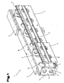
- Carrier 1 illustrated on the basis of a cutout comprises a top chord composed of upper chord modules 2 arranged one behind the other in the longitudinal direction of the carrier 1, a bottom chord composed of bottom chord modules 3 arranged one behind the other in the longitudinal direction of the carrier 1, a front wall composed of front wall modules 4 arranged one behind the other in the longitudinal direction of the carrier 1 a composed of in the longitudinal direction of the carrier 1 successively arranged rear wall modules 5 rear wall.
- transverse webs 6 are arranged at intervals, which are arranged at right angles to said modules and connected thereto.
- Fig. 1 It can clearly be seen that the various modules 2, 3, 4, 5 are offset from each other in the longitudinal direction of the carrier 1, such that, for example, the point at which two upper belt modules 2 arranged one behind the other do not lie in the same cross-sectional plane of the carrier as the point where two successively arranged front wall modules 4 abut each other. As a result, the bending stability of the carrier 1 is kept constant over its length. How to get in Fig. 1 sees, the offset of the modules has the consequence that in the end of the carrier, for example, the front wall module 4 (left in Fig. 1 ) is shorter than the adjacent front wall module.
- the modules 2, 3, 4, 5 are connected to each other, in particular by gluing.
- the modules are preferably connected together by pins or screws.
- the connection of the modules by pins in particular improves the positioning accuracy of the modules with each other.
- fastening or positioning holes can be provided.
- adhesive bonds between the modules 2, 3, 4, 5 and welding or solder joints could be provided.
- this is not particularly advantageous because of the associated heating of the parts in view of the desired high precision of the guideways.
- different materials can be used for the different modules 2, 3, 4, 5.
- carbon fibers can be inserted into the splices between the modules.
- Fig. 1 that in the modules 2, 3, 4, 5 recesses may be present, for example, recesses 13 in the transverse webs 6, recesses 14 in the rear wall modules 5 and recesses 15 in the front wall modules 4. These recesses serve primarily to reduce the mass of the carrier 1 without reducing its rigidity.
- a first guideway 7 is shown, which extends over the upper sides of the lower chord modules 3 in the longitudinal direction of the carrier 1.
- a second guideway 9 extends over the upper longitudinal edges of the front wall modules 4.
- the purpose of the guideways 7, 9 is to serve as a raceway for a subassembly movable along the carrier 1, for example a printhead. Since particularly high demands are placed on these guideways with regard to their precision, especially in the case of large-format printing, these are only machined, for example milled, ground, lapped or scraped, over the entire length of the carrier after assembly of the carrier 1.
- 5 guideways may also be present on the upper belt modules 2 and / or the rear wall modules.
- FIG. 2 In the cross-sectional representation of Fig. 2 clearly shows the arrangement of the first guide track 7 at the top of the lower flange modules 3, which protrude laterally beyond the front wall modules 4 addition. It can also be seen that the second guide track 9 extends over the upper edge of the front wall modules 4, which upper edge projects vertically beyond the upper belt modules 2. With this design, the guide surfaces are free and can be easily subjected to a precision machining.
- Fig. 2 further shows that the corners of the transverse webs 6 are broken, resulting in over the entire length of the support 1 extending corner spaces 11.
- traction means 12 such as steel cables or carbon fiber bundles.
- This traction means are anchored and biased in the front ends of the carrier 1, whereby the rigidity of the carrier 1 is additionally increased and the bending behavior of the carrier can be positively influenced under load.
- Fig. 3 shows another way to achieve the required high precision of the guideways by the latter are formed as connected to the carrier 1 precision profiles.
- a first profile 8 is disposed on over the front wall projecting portions of the lower flange modules 3 and a second profile 10 is on the upper longitudinal edges of the front wall modules 4 attached.
- the profiles 8, 9 can also be adhesively bonded to the respective modules of the carrier 1 and additionally positioned and secured by pins and / or screws and extend along the length of several modules, preferably over the entire length of the carrier.
- a carrier according to the invention used for a large-format printer may, for example, have the following dimensions. Length 6'000 mm, height 400 mm and width 300 mm.
Landscapes
- Character Spaces And Line Spaces In Printers (AREA)
- Machine Tool Units (AREA)
- Bearings For Parts Moving Linearly (AREA)
Claims (9)
- Procédé de fabrication d'un support (1) conçu comme corps creux prismatique, dont les parois sont formées par l'assemblage de modules de membrure supérieure (2), modules de membrure inférieure (3), modules de paroi avant (4) et modules de paroi arrière (5) disposés les uns derrière les autres respectivement dans le sens longitudinal du support (1), des entretoises transversales (6) étant disposées à l'intérieur du support (1) à des intervalles et au moins une bande de guidage (7, 9) agencée dans son sens longitudinal étant disposée sur le support (1) pour un ensemble mobile le long de la bande de guidage (7, 9), caractérisé en ce que les modules (2, 3, 4, 5) formant les parois individuelles sont disposés respectivement dans le sens longitudinal du support (1) les uns derrière les autres, les points de jonction ainsi respectivement formés n'étant pas alignés avec des endroits sur lesquels est présent un point de jonction de modules voisins dans le sens longitudinal, et en ce que la au moins une bande de guidage (7, 9) est formée du fait que des zones des modules (2, 3, 4, 5) sont usinées par enlèvement de copeaux après l'assemblage des modules (2, 3, 4, 5) et des entretoises transversales (6).
- Support (1) conçu comme corps creux prismatique fabriqué par un procédé selon la revendication 1, dont les parois sont formées de modules de membrure supérieure (2), modules de membrure inférieure (3), modules de paroi avant (4) et modules de paroi arrière (5) disposés les uns derrière les autres dans le sens longitudinal du support (1), des entretoises transversales (6) étant disposées à l'intérieur du support (1) à des intervalles et au moins une bande de guidage agencée dans son sens longitudinal étant disposée sur le support (1) pour un ensemble mobile le long de la bande de guidage, caractérisé en ce que la au moins une bande de guidage est formée par au moins un profilé (8, 10) s'étendant sur la longueur de plusieurs modules (2, 3, 4, 5).
- Support selon la revendication 2, caractérisé en ce que les modules (2, 3, 4, 5) sont décalés les uns par rapport aux autres dans le sens longitudinal du support (1), de telle sorte que des endroits, sur lesquels deux modules (2, 3, 4, 5) disposés l'un derrière l'autre dans le sens longitudinal du support (1) se touchent, ne sont pas alignés avec des endroits sur lesquels deux modules (2, 3, 4, 5), disposés l'un derrière l'autre dans le sens longitudinal du support (1) de la paroi voisine du support (1) se touchent.
- Support selon la revendication 2 ou 3, caractérisé en ce que les modules (2, 3, 4, 5) entre eux et/ou les modules (2, 3, 4, 5) et les entretoises transversales (6) sont à base de différents matériaux.
- Support selon l'une quelconque des revendications 2 à 4, caractérisé en ce que les modules (2, 3, 4, 5) entre eux et/ou les modules (2, 3, 4, 5) et les entretoises transversales (6) sont reliés les uns aux autres par collage.
- Support selon la revendication 5, caractérisé en ce que des fibres de carbone sont intégrées dans les joints de collage.
- Support selon l'une quelconque des revendications 2 à 6, caractérisé en ce que les modules (2, 3, 4, 5) entre eux et/ou les modules (2, 3, 4, 5) et les entretoises transversales (6) sont reliés entre eux par des broches.
- Support selon l'une quelconque des revendications 2 à 7, caractérisé en ce que les modules (2, 3, 4, 5) entre eux et/ou les modules (2, 3, 4, 5) et les entretoises transversales (6) sont reliés les uns aux autres par des vis.
- Support selon l'une quelconque des revendications 2 à 8, caractérisé en ce que des moyens de traction (12) précontraints, agencés dans le sens longitudinal, sont disposés à l'intérieur du support (1).
Priority Applications (1)
| Application Number | Priority Date | Filing Date | Title |
|---|---|---|---|
| SI200830519T SI2000316T1 (sl) | 2007-06-04 | 2008-06-03 | Postopek za izdelavo nosilca in nosilec |
Applications Claiming Priority (1)
| Application Number | Priority Date | Filing Date | Title |
|---|---|---|---|
| ATA882/2007A AT505426B1 (de) | 2007-06-04 | 2007-06-04 | Verfahren zur herstellung eines trägers und träger |
Publications (2)
| Publication Number | Publication Date |
|---|---|
| EP2000316A1 EP2000316A1 (fr) | 2008-12-10 |
| EP2000316B1 true EP2000316B1 (fr) | 2011-10-19 |
Family
ID=39800535
Family Applications (1)
| Application Number | Title | Priority Date | Filing Date |
|---|---|---|---|
| EP08010099A Not-in-force EP2000316B1 (fr) | 2007-06-04 | 2008-06-03 | Procédé de fabrication d'un support et support |
Country Status (7)
| Country | Link |
|---|---|
| US (1) | US8622639B2 (fr) |
| EP (1) | EP2000316B1 (fr) |
| JP (1) | JP5274111B2 (fr) |
| AT (2) | AT505426B1 (fr) |
| ES (1) | ES2375296T3 (fr) |
| IL (1) | IL191956A (fr) |
| SI (1) | SI2000316T1 (fr) |
Families Citing this family (7)
| Publication number | Priority date | Publication date | Assignee | Title |
|---|---|---|---|---|
| AT508825B1 (de) * | 2009-09-15 | 2012-06-15 | Durst Phototechnik Digital Technology Gmbh | Traganordnung für eine tintenstrahl-druckvorrichtung |
| DE102010041864A1 (de) * | 2010-10-01 | 2012-04-05 | Otto Bihler Handels-Beteiligungs-Gmbh | Halterungsmodul für Fertigungs- und/oder Montagekomponenten einer Bearbeitungsanlage sowie eine mit einem solchen Halterungsmodul ausgestattete Bearbeitungsanlage |
| US20160112684A1 (en) * | 2013-05-23 | 2016-04-21 | Medibotics Llc | Spectroscopic Finger Ring for Compositional Analysis of Food or Other Environmental Objects |
| WO2015082510A1 (fr) | 2013-12-06 | 2015-06-11 | Oce-Technologies B.V. | Système d'impression à jet d'encre à balayage |
| EP3077208B1 (fr) | 2013-12-06 | 2021-04-14 | Canon Production Printing Netherlands B.V. | Système d'impression à jet d'encre de balayage |
| US20150345613A1 (en) * | 2014-05-27 | 2015-12-03 | VVhite Rock II, LLC | Transfer case support system |
| EP3564038A1 (fr) * | 2018-05-04 | 2019-11-06 | OCE Holding B.V. | Structure de guidage pour un chariot de tête d'impression |
Family Cites Families (13)
| Publication number | Priority date | Publication date | Assignee | Title |
|---|---|---|---|---|
| US4248025A (en) * | 1979-08-08 | 1981-02-03 | Unarco Industries, Inc. | Knock down pole construction |
| DE3114567A1 (de) * | 1981-04-10 | 1982-10-28 | Messerschmitt-Bölkow-Blohm GmbH, 8000 München | "grossflaechiges rotorblatt" |
| DE3705773A1 (de) * | 1987-02-24 | 1988-09-01 | Dyckerhoff & Widmann Ag | Verfahren zur justierung, befestigung und/oder bearbeitung von funktionsflaechen eines fahrwegs einer elektromagnetischen schnellbahn |
| ES2244146T3 (es) * | 1999-02-17 | 2005-12-01 | Hewlett-Packard Company, A Delaware Corporation | Chasis de impresora. |
| JP2000263356A (ja) | 1999-03-15 | 2000-09-26 | Mitsubishi Electric Corp | 工作機械 |
| DE19942057A1 (de) * | 1999-09-03 | 2001-03-08 | Schaeffler Waelzlager Ohg | Linearführung für eine Werkzeugmaschine |
| US6332301B1 (en) * | 1999-12-02 | 2001-12-25 | Jacob Goldzak | Metal beam structure and building construction including same |
| US6427310B1 (en) * | 2000-02-15 | 2002-08-06 | Eastman Kodak Company | Method for fabricating a print engine chassis for supporting an imaging drum and printhead translation assembly |
| DE10009713A1 (de) * | 2000-03-02 | 2001-09-13 | Stefan Thiesbrummel | Vorschub- und Übergabemodul |
| GB2387816A (en) * | 2002-04-27 | 2003-10-29 | Hewlett Packard Co | Scan axis assembly for printer comprising first and second print carriage tracks supporting first and second print cartridges |
| JP2003340661A (ja) | 2002-05-17 | 2003-12-02 | Mori Seiki Co Ltd | 加工方法及び加工装置、並びに該加工装置を備えた加工システム |
| JP4675607B2 (ja) * | 2004-10-29 | 2011-04-27 | ヤマザキマザック株式会社 | 工作機械のベッド |
| EP1854577B1 (fr) | 2006-05-12 | 2016-06-29 | Yamazaki Mazak Corporation | Méthode de fabrication d'une colonne et d'un banc pour une machine d'usinage et structure associé |
-
2007
- 2007-06-04 AT ATA882/2007A patent/AT505426B1/de not_active IP Right Cessation
-
2008
- 2008-06-03 AT AT08010099T patent/ATE529263T1/de active
- 2008-06-03 SI SI200830519T patent/SI2000316T1/sl unknown
- 2008-06-03 ES ES08010099T patent/ES2375296T3/es active Active
- 2008-06-03 US US12/156,555 patent/US8622639B2/en not_active Expired - Fee Related
- 2008-06-03 EP EP08010099A patent/EP2000316B1/fr not_active Not-in-force
- 2008-06-04 JP JP2008146785A patent/JP5274111B2/ja not_active Expired - Fee Related
- 2008-06-04 IL IL191956A patent/IL191956A/en not_active IP Right Cessation
Also Published As
| Publication number | Publication date |
|---|---|
| EP2000316A1 (fr) | 2008-12-10 |
| AT505426A1 (de) | 2009-01-15 |
| JP5274111B2 (ja) | 2013-08-28 |
| ATE529263T1 (de) | 2011-11-15 |
| IL191956A (en) | 2012-10-31 |
| JP2009006472A (ja) | 2009-01-15 |
| ES2375296T3 (es) | 2012-02-28 |
| SI2000316T1 (sl) | 2012-02-29 |
| AT505426B1 (de) | 2013-04-15 |
| IL191956A0 (en) | 2009-02-11 |
| US20090001243A1 (en) | 2009-01-01 |
| US8622639B2 (en) | 2014-01-07 |
Similar Documents
| Publication | Publication Date | Title |
|---|---|---|
| EP2000316B1 (fr) | Procédé de fabrication d'un support et support | |
| DE102004014745B4 (de) | Frachtdeck | |
| DE3502820A1 (de) | Fertigungsanlage mit mehreren einzelstationen | |
| EP1070786A2 (fr) | Voie pour transport à lévitation magnétique avec propulsion linéaire par stator longitudinal, ensemble de construction , et méthode pour son obtention | |
| DE102007024589A1 (de) | Bearbeitungs-, insbesondere Geometrieschweißstation | |
| EP3040296A1 (fr) | Systeme de transfert/montage modulaire | |
| DE202015106966U1 (de) | Keiltrieb | |
| DE102010048350A1 (de) | Bodengruppe für eine Mehrzahl von Bauvarianten einer Karosserie eines Personenkraftwagens | |
| DE102011121584A1 (de) | Modulares Tragsystem zur Fixierung von Bauteilen | |
| DE10333561B4 (de) | Koordinaten-Meßmaschine | |
| DE69926723T2 (de) | Gestell eines Druckers | |
| EP2786922A1 (fr) | Carrosserie d'un véhicule automobile réalisée en éléments en polymère et connections entre ces éléments | |
| WO2003102303A1 (fr) | Voie de communication, module pour voie de communication et procede de fabrication dudit module | |
| DE102018213760A1 (de) | Aufzugsanlage | |
| DE102010031728A1 (de) | Verfahren zur Montage einer Tür an einem Fahrzeug | |
| DE19513537A1 (de) | Maschinengestell | |
| EP1366850A1 (fr) | Guidage linéaire avec un rail de guidage et une crémaillère | |
| EP2845663B1 (fr) | Presse plieuse avec un outil de cintrage composé de plusieurs éléments d'outil | |
| EP1632308A1 (fr) | Guidage linéaire avec deux rails de guidage parallèles et procédé pour sa fabrication | |
| DE19781491B4 (de) | Stufenpresse | |
| DE20208421U1 (de) | Biegeträger aus Stahl für eine Spurwechseleinrichtung bei Fahrwegen von Magnetschwebefahrzeugen | |
| DE10319101B4 (de) | Zahnstange für einen Zahnriemenantrieb | |
| EP2063132A1 (fr) | Dispositif d'entraînement linéaire | |
| DE102005022397A1 (de) | Spinnmaschine und Verfahren zum Zusammenbau | |
| EP3789808B1 (fr) | Organe de couplage pour un dispositif de positionnement ainsi que dispositif de positionnement doté d'un organe de couplage |
Legal Events
| Date | Code | Title | Description |
|---|---|---|---|
| PUAI | Public reference made under article 153(3) epc to a published international application that has entered the european phase |
Free format text: ORIGINAL CODE: 0009012 |
|
| AK | Designated contracting states |
Kind code of ref document: A1 Designated state(s): AT BE BG CH CY CZ DE DK EE ES FI FR GB GR HR HU IE IS IT LI LT LU LV MC MT NL NO PL PT RO SE SI SK TR |
|
| AX | Request for extension of the european patent |
Extension state: AL BA MK RS |
|
| 17P | Request for examination filed |
Effective date: 20090608 |
|
| 17Q | First examination report despatched |
Effective date: 20090710 |
|
| AKX | Designation fees paid |
Designated state(s): AT BE BG CH CY CZ DE DK EE ES FI FR GB GR HR HU IE IS IT LI LT LU LV MC MT NL NO PL PT RO SE SI SK TR |
|
| GRAP | Despatch of communication of intention to grant a patent |
Free format text: ORIGINAL CODE: EPIDOSNIGR1 |
|
| GRAS | Grant fee paid |
Free format text: ORIGINAL CODE: EPIDOSNIGR3 |
|
| GRAA | (expected) grant |
Free format text: ORIGINAL CODE: 0009210 |
|
| AK | Designated contracting states |
Kind code of ref document: B1 Designated state(s): AT BE BG CH CY CZ DE DK EE ES FI FR GB GR HR HU IE IS IT LI LT LU LV MC MT NL NO PL PT RO SE SI SK TR |
|
| REG | Reference to a national code |
Ref country code: GB Ref legal event code: FG4D Free format text: NOT ENGLISH |
|
| REG | Reference to a national code |
Ref country code: CH Ref legal event code: EP |
|
| REG | Reference to a national code |
Ref country code: IE Ref legal event code: FG4D |
|
| REG | Reference to a national code |
Ref country code: DE Ref legal event code: R096 Ref document number: 502008005213 Country of ref document: DE Effective date: 20111215 |
|
| REG | Reference to a national code |
Ref country code: CH Ref legal event code: NV Representative=s name: ABP PATENT NETWORK SWISS GMBH |
|
| REG | Reference to a national code |
Ref country code: NL Ref legal event code: VDEP Effective date: 20111019 |
|
| REG | Reference to a national code |
Ref country code: ES Ref legal event code: FG2A Ref document number: 2375296 Country of ref document: ES Kind code of ref document: T3 Effective date: 20120228 |
|
| LTIE | Lt: invalidation of european patent or patent extension |
Effective date: 20111019 |
|
| PG25 | Lapsed in a contracting state [announced via postgrant information from national office to epo] |
Ref country code: LT Free format text: LAPSE BECAUSE OF FAILURE TO SUBMIT A TRANSLATION OF THE DESCRIPTION OR TO PAY THE FEE WITHIN THE PRESCRIBED TIME-LIMIT Effective date: 20111019 Ref country code: NO Free format text: LAPSE BECAUSE OF FAILURE TO SUBMIT A TRANSLATION OF THE DESCRIPTION OR TO PAY THE FEE WITHIN THE PRESCRIBED TIME-LIMIT Effective date: 20120119 Ref country code: IS Free format text: LAPSE BECAUSE OF FAILURE TO SUBMIT A TRANSLATION OF THE DESCRIPTION OR TO PAY THE FEE WITHIN THE PRESCRIBED TIME-LIMIT Effective date: 20120219 |
|
| REG | Reference to a national code |
Ref country code: IE Ref legal event code: FD4D |
|
| PG25 | Lapsed in a contracting state [announced via postgrant information from national office to epo] |
Ref country code: SE Free format text: LAPSE BECAUSE OF FAILURE TO SUBMIT A TRANSLATION OF THE DESCRIPTION OR TO PAY THE FEE WITHIN THE PRESCRIBED TIME-LIMIT Effective date: 20111019 Ref country code: PT Free format text: LAPSE BECAUSE OF FAILURE TO SUBMIT A TRANSLATION OF THE DESCRIPTION OR TO PAY THE FEE WITHIN THE PRESCRIBED TIME-LIMIT Effective date: 20120220 Ref country code: NL Free format text: LAPSE BECAUSE OF FAILURE TO SUBMIT A TRANSLATION OF THE DESCRIPTION OR TO PAY THE FEE WITHIN THE PRESCRIBED TIME-LIMIT Effective date: 20111019 Ref country code: HR Free format text: LAPSE BECAUSE OF FAILURE TO SUBMIT A TRANSLATION OF THE DESCRIPTION OR TO PAY THE FEE WITHIN THE PRESCRIBED TIME-LIMIT Effective date: 20111019 Ref country code: GR Free format text: LAPSE BECAUSE OF FAILURE TO SUBMIT A TRANSLATION OF THE DESCRIPTION OR TO PAY THE FEE WITHIN THE PRESCRIBED TIME-LIMIT Effective date: 20120120 Ref country code: LV Free format text: LAPSE BECAUSE OF FAILURE TO SUBMIT A TRANSLATION OF THE DESCRIPTION OR TO PAY THE FEE WITHIN THE PRESCRIBED TIME-LIMIT Effective date: 20111019 |
|
| PG25 | Lapsed in a contracting state [announced via postgrant information from national office to epo] |
Ref country code: CY Free format text: LAPSE BECAUSE OF FAILURE TO SUBMIT A TRANSLATION OF THE DESCRIPTION OR TO PAY THE FEE WITHIN THE PRESCRIBED TIME-LIMIT Effective date: 20111019 |
|
| PG25 | Lapsed in a contracting state [announced via postgrant information from national office to epo] |
Ref country code: EE Free format text: LAPSE BECAUSE OF FAILURE TO SUBMIT A TRANSLATION OF THE DESCRIPTION OR TO PAY THE FEE WITHIN THE PRESCRIBED TIME-LIMIT Effective date: 20111019 Ref country code: CZ Free format text: LAPSE BECAUSE OF FAILURE TO SUBMIT A TRANSLATION OF THE DESCRIPTION OR TO PAY THE FEE WITHIN THE PRESCRIBED TIME-LIMIT Effective date: 20111019 Ref country code: SK Free format text: LAPSE BECAUSE OF FAILURE TO SUBMIT A TRANSLATION OF THE DESCRIPTION OR TO PAY THE FEE WITHIN THE PRESCRIBED TIME-LIMIT Effective date: 20111019 Ref country code: BG Free format text: LAPSE BECAUSE OF FAILURE TO SUBMIT A TRANSLATION OF THE DESCRIPTION OR TO PAY THE FEE WITHIN THE PRESCRIBED TIME-LIMIT Effective date: 20120119 Ref country code: IE Free format text: LAPSE BECAUSE OF FAILURE TO SUBMIT A TRANSLATION OF THE DESCRIPTION OR TO PAY THE FEE WITHIN THE PRESCRIBED TIME-LIMIT Effective date: 20111019 Ref country code: DK Free format text: LAPSE BECAUSE OF FAILURE TO SUBMIT A TRANSLATION OF THE DESCRIPTION OR TO PAY THE FEE WITHIN THE PRESCRIBED TIME-LIMIT Effective date: 20111019 |
|
| PLBE | No opposition filed within time limit |
Free format text: ORIGINAL CODE: 0009261 |
|
| STAA | Information on the status of an ep patent application or granted ep patent |
Free format text: STATUS: NO OPPOSITION FILED WITHIN TIME LIMIT |
|
| PG25 | Lapsed in a contracting state [announced via postgrant information from national office to epo] |
Ref country code: RO Free format text: LAPSE BECAUSE OF FAILURE TO SUBMIT A TRANSLATION OF THE DESCRIPTION OR TO PAY THE FEE WITHIN THE PRESCRIBED TIME-LIMIT Effective date: 20111019 Ref country code: PL Free format text: LAPSE BECAUSE OF FAILURE TO SUBMIT A TRANSLATION OF THE DESCRIPTION OR TO PAY THE FEE WITHIN THE PRESCRIBED TIME-LIMIT Effective date: 20111019 |
|
| 26N | No opposition filed |
Effective date: 20120720 |
|
| REG | Reference to a national code |
Ref country code: DE Ref legal event code: R097 Ref document number: 502008005213 Country of ref document: DE Effective date: 20120720 |
|
| BERE | Be: lapsed |
Owner name: DURST PHOTOTECHNIK DIGITAL TECHNOLOGY GMBH Effective date: 20120630 |
|
| PG25 | Lapsed in a contracting state [announced via postgrant information from national office to epo] |
Ref country code: MC Free format text: LAPSE BECAUSE OF NON-PAYMENT OF DUE FEES Effective date: 20120630 |
|
| PG25 | Lapsed in a contracting state [announced via postgrant information from national office to epo] |
Ref country code: BE Free format text: LAPSE BECAUSE OF NON-PAYMENT OF DUE FEES Effective date: 20120630 |
|
| PG25 | Lapsed in a contracting state [announced via postgrant information from national office to epo] |
Ref country code: FI Free format text: LAPSE BECAUSE OF FAILURE TO SUBMIT A TRANSLATION OF THE DESCRIPTION OR TO PAY THE FEE WITHIN THE PRESCRIBED TIME-LIMIT Effective date: 20111019 |
|
| PG25 | Lapsed in a contracting state [announced via postgrant information from national office to epo] |
Ref country code: MT Free format text: LAPSE BECAUSE OF FAILURE TO SUBMIT A TRANSLATION OF THE DESCRIPTION OR TO PAY THE FEE WITHIN THE PRESCRIBED TIME-LIMIT Effective date: 20111019 |
|
| REG | Reference to a national code |
Ref country code: CH Ref legal event code: NV Representative=s name: ABP PATENT NETWORK AG, CH |
|
| PGFP | Annual fee paid to national office [announced via postgrant information from national office to epo] |
Ref country code: SI Payment date: 20130529 Year of fee payment: 6 |
|
| PG25 | Lapsed in a contracting state [announced via postgrant information from national office to epo] |
Ref country code: LU Free format text: LAPSE BECAUSE OF NON-PAYMENT OF DUE FEES Effective date: 20120603 |
|
| PG25 | Lapsed in a contracting state [announced via postgrant information from national office to epo] |
Ref country code: HU Free format text: LAPSE BECAUSE OF FAILURE TO SUBMIT A TRANSLATION OF THE DESCRIPTION OR TO PAY THE FEE WITHIN THE PRESCRIBED TIME-LIMIT Effective date: 20080603 |
|
| REG | Reference to a national code |
Ref country code: SI Ref legal event code: KO00 Effective date: 20150213 |
|
| PG25 | Lapsed in a contracting state [announced via postgrant information from national office to epo] |
Ref country code: SI Free format text: LAPSE BECAUSE OF NON-PAYMENT OF DUE FEES Effective date: 20140604 |
|
| REG | Reference to a national code |
Ref country code: FR Ref legal event code: PLFP Year of fee payment: 9 |
|
| REG | Reference to a national code |
Ref country code: CH Ref legal event code: PCAR Free format text: NEW ADDRESS: OTHMARSTRASSE 8, 8008 ZUERICH (CH) |
|
| PGFP | Annual fee paid to national office [announced via postgrant information from national office to epo] |
Ref country code: CH Payment date: 20170612 Year of fee payment: 10 Ref country code: GB Payment date: 20170608 Year of fee payment: 10 Ref country code: DE Payment date: 20170602 Year of fee payment: 10 |
|
| REG | Reference to a national code |
Ref country code: FR Ref legal event code: PLFP Year of fee payment: 10 |
|
| PGFP | Annual fee paid to national office [announced via postgrant information from national office to epo] |
Ref country code: TR Payment date: 20170531 Year of fee payment: 10 |
|
| PGFP | Annual fee paid to national office [announced via postgrant information from national office to epo] |
Ref country code: ES Payment date: 20170701 Year of fee payment: 10 Ref country code: FR Payment date: 20170817 Year of fee payment: 10 |
|
| REG | Reference to a national code |
Ref country code: DE Ref legal event code: R119 Ref document number: 502008005213 Country of ref document: DE |
|
| REG | Reference to a national code |
Ref country code: CH Ref legal event code: PL |
|
| GBPC | Gb: european patent ceased through non-payment of renewal fee |
Effective date: 20180603 |
|
| PG25 | Lapsed in a contracting state [announced via postgrant information from national office to epo] |
Ref country code: FR Free format text: LAPSE BECAUSE OF NON-PAYMENT OF DUE FEES Effective date: 20180630 Ref country code: CH Free format text: LAPSE BECAUSE OF NON-PAYMENT OF DUE FEES Effective date: 20180630 Ref country code: GB Free format text: LAPSE BECAUSE OF NON-PAYMENT OF DUE FEES Effective date: 20180603 Ref country code: LI Free format text: LAPSE BECAUSE OF NON-PAYMENT OF DUE FEES Effective date: 20180630 Ref country code: DE Free format text: LAPSE BECAUSE OF NON-PAYMENT OF DUE FEES Effective date: 20190101 |
|
| PGFP | Annual fee paid to national office [announced via postgrant information from national office to epo] |
Ref country code: IT Payment date: 20190312 Year of fee payment: 12 |
|
| REG | Reference to a national code |
Ref country code: ES Ref legal event code: FD2A Effective date: 20190916 |
|
| PG25 | Lapsed in a contracting state [announced via postgrant information from national office to epo] |
Ref country code: ES Free format text: LAPSE BECAUSE OF NON-PAYMENT OF DUE FEES Effective date: 20180604 |
|
| PGFP | Annual fee paid to national office [announced via postgrant information from national office to epo] |
Ref country code: AT Payment date: 20190516 Year of fee payment: 12 |
|
| REG | Reference to a national code |
Ref country code: AT Ref legal event code: MM01 Ref document number: 529263 Country of ref document: AT Kind code of ref document: T Effective date: 20200603 |
|
| PG25 | Lapsed in a contracting state [announced via postgrant information from national office to epo] |
Ref country code: AT Free format text: LAPSE BECAUSE OF NON-PAYMENT OF DUE FEES Effective date: 20200603 |
|
| PG25 | Lapsed in a contracting state [announced via postgrant information from national office to epo] |
Ref country code: IT Free format text: LAPSE BECAUSE OF NON-PAYMENT OF DUE FEES Effective date: 20200603 |
|
| PG25 | Lapsed in a contracting state [announced via postgrant information from national office to epo] |
Ref country code: TR Free format text: LAPSE BECAUSE OF NON-PAYMENT OF DUE FEES Effective date: 20180603 |