EP2000866A2 - Dispositif de surveillance destiné à la reconnaissance de l'état d'un bus - Google Patents
Dispositif de surveillance destiné à la reconnaissance de l'état d'un bus Download PDFInfo
- Publication number
- EP2000866A2 EP2000866A2 EP08009811A EP08009811A EP2000866A2 EP 2000866 A2 EP2000866 A2 EP 2000866A2 EP 08009811 A EP08009811 A EP 08009811A EP 08009811 A EP08009811 A EP 08009811A EP 2000866 A2 EP2000866 A2 EP 2000866A2
- Authority
- EP
- European Patent Office
- Prior art keywords
- bus
- actuator
- asi
- sensor interface
- monitoring device
- Prior art date
- Legal status (The legal status is an assumption and is not a legal conclusion. Google has not performed a legal analysis and makes no representation as to the accuracy of the status listed.)
- Granted
Links
Images

Classifications
-
- G—PHYSICS
- G05—CONTROLLING; REGULATING
- G05B—CONTROL OR REGULATING SYSTEMS IN GENERAL; FUNCTIONAL ELEMENTS OF SUCH SYSTEMS; MONITORING OR TESTING ARRANGEMENTS FOR SUCH SYSTEMS OR ELEMENTS
- G05B19/00—Program-control systems
- G05B19/02—Program-control systems electric
- G05B19/04—Program control other than numerical control, i.e. in sequence controllers or logic controllers
- G05B19/042—Program control other than numerical control, i.e. in sequence controllers or logic controllers using digital processors
- G05B19/0423—Input/output
- G05B19/0425—Safety, monitoring
-
- G—PHYSICS
- G05—CONTROLLING; REGULATING
- G05B—CONTROL OR REGULATING SYSTEMS IN GENERAL; FUNCTIONAL ELEMENTS OF SUCH SYSTEMS; MONITORING OR TESTING ARRANGEMENTS FOR SUCH SYSTEMS OR ELEMENTS
- G05B2219/00—Program-control systems
- G05B2219/20—Pc systems
- G05B2219/21—Pc I-O input output
- G05B2219/21123—Impedance matching
Definitions
- the invention relates to a monitoring device for detecting the state of a bus, in particular for detecting a faulty addressing of a slave, in a one master, a plurality of slaves, a power supply and a signal and energy-transmitting bus having fieldbus system.
- the invention also relates to a corresponding method for detecting the state of a bus with a monitoring device and an actuator-sensor interface system with an actuator-sensor interface master, at least two actuator-sensor interface slaves, an actuator sensor Interface power supply and an actuator-sensor interface bus, wherein the actuator-sensor interface power supply supplies the actuator-sensor interface slaves via the actuator-sensor interface bus with a DC voltage, wherein the actuator Sensor Interface Bus Signals which are modulated as AC signals of the DC voltage, are serially transferable between the actuator-sensor interface master and the actuator-sensor interface slaves, each actuator-sensor-interface slave being assigned a binary address is such that each actuator sensor interface slave by a master address containing its address from the actuator-sensor interface master for delivering a slave answer t can be caused.
- bus systems In measurement and automation technology, various bus systems have been used for about two decades, often referred to as fieldbus systems.
- An essential feature of such bus systems is the digital transmission of information via a bus line.
- the different bus systems can be divided into three levels. The first, top level forms the field level, in which individual automation islands are interconnected and linked into larger units. The next level is the device level, in which more complex sensors and actuators as well as simple automation devices are connected to each other and to a higher-level controller. The lowest level is the sensor-acutator level, where the numerically most common binary sensors and actuators are connected. (see. " AS-Interface The Solution in Automation ", Rolf Becker, et al., AS-International Association, 2002, pages 14 to 17 ).
- an actuator-sensor-interface system which is referred to as an AS-interface system or always referred to below as an ASI system.
- the ASI system has been used as a novel interface since 1994 for industrial communication and occupies the area below the previous fieldbus systems. It combines in particular binary sensors and actuators, but also analog sensors via a common bus with the first control level, z. A PLC or a PC.
- the ASI system is internationally standardized by standards EN 50295 and IEC 62026-2 (see " AS-Interface The solution in automation ", Rolf Becker, et al., AS-International Association, 2002 ).
- the invention is not limited to use in such an ASI system, but can in principle also in other Bus systems or be used in other types of bus lines.
- the only prerequisite is that it is a bus system in which both the power supply of the slaves and possibly the master, as well as the data transmission between the slaves with each other and between the slaves and the master via the bus.
- Such bus systems are also referred to as "loop-powered" buses or bus systems.
- the ASI system consists of an ASI master, several ASI slaves, one ASI power supply and one ASI cable.
- An essential component of the ASI system is the ASI slave, which is usually implemented as an ASI chip and with which the actuators or sensors are digitally coupled to a bus line, the ASI line.
- the ASI chip is either built into a module, to which conventional actuators and sensors are connected, or it is installed directly in the actuator or sensor.
- the ASI master forms the interface between the actuators or sensors and the core of the controller, for example a PLC or a PC (cf. AS-Interface The solution in automation ", page 53 ff ).
- the ASI power supply primarily serves the power supply of the slaves (and thus also the actuators and sensors connected to the slaves) and at least part of the master.
- the ASI power supply provides a DC voltage of approx. 30V at currents up to 8A.
- the ASI power supply also serves to balance the ASI network and to decouple data.
- the ASI power supply has a symmetry circuit and a data decoupling network, wherein the data decoupling network consists of two inductors and two resistors connected in parallel (see "AS-Interface The Solution in Automation", page 60 f).
- the ASI cable uses an unshielded 2-conductor ribbon cable (2 x 1.5 mm 2 ) or a standard round cable, which simultaneously transmits signals and energy.
- the power supply of the slaves and the master as well as the data transmission between the slaves with each other as well as between the slaves and the master takes place via the ASI line (cf. AS-Interface The Solution in Automation ", page 56 - 60 ).
- a special modulation method For the simultaneous transmission of the signals and the energy via the ASI line, a special modulation method has been developed, which meets the numerous requirements of the ASI system in a special way.
- the message signal which is superimposed on the power supply of the ASI slaves, must be DC-free and relatively narrow-band and also must not radiate electromagnetic radiation in an inadmissible manner.
- an alternating pulse modulation APM
- APM alternating pulse modulation
- the transmit bit sequence is first transcoded into a Manchester-encoded (MAN-encoded) bit sequence which makes a phase change each time the transmit signal is changed. From the coded bit sequence, a transmission current is then generated, from which the desired signal voltage level is generated on the ASI line by differentiation.
- these voltage signals are detected on the line and converted back into the transmitted bit sequence. If the voltage pulses are approximately shaped like sin 2 pulses, the demands for a lower cutoff frequency and low noise radiation are taken into account at the same time (cf. AS-Interface The Solution in Automation ", page 62 - 65 ).
- the ASI system is a master-slave system with cyclic polling and uses one master per network, which cyclically calls all subscribers (slaves) with their address.
- the ASI system transfers the information (ASI messages) between a master and the different slaves not in parallel, but serially.
- the ASI messages are short, simply structured and have a fixed length. In each polling cycle, information is transmitted serially from master to each slave and back. They can be used as input or as output data.
- the ASI system has a specific structure of the signals transmitted via the ASI line. This structure of the transmitted signals, d. H.
- the structure of the ASI messages, together with a predefined maximum number of ASI slaves that can be connected to the ASI line, ensure a cycle time of 5 ms that is sufficient for practical purposes in many cases.
- the dialog of the ASI master with an ASI slave always consists of the combination of the telegram of the ASI master and the response telegram of the ASI slave.
- the telegram of the ASI master is also called the master call
- the response telegram of the ASI slave is called the slave response.
- the telegrams start, ie. H. the ASI messages with a start identifier and end with a stop identifier.
- a master break or a slave pause is provided in each case.
- the master call consists of a total of fourteen bits, which contains five address bits and five information bits to the ASI slave.
- the slave response consists of a total of seven bits, of which four bits are provided as information bits to the ASI master. The remaining bits, such as start bit, control bit, parity bit or end bit, are used for data backup and error detection.
- the address bits at the beginning of the master call inform each ASI slave whether the following information is intended for it or for another ASI slave.
- Each ASI slave is assigned a five-bit long address, with the address 0 having a special function. It is usually used in the production as a default value, ie manufacturing terms the address 0 is assigned to the ASI slaves. If, for example, a defective ASI slave is replaced, the new ASI slave replaces address 0 with the address of the failed ASI slave, which can be executed by a corresponding ASI master command to the new ASI slave.
- the five address bits a maximum of 31 subscribers can thus be addressed in NonnalfaII and connected to the ASI line.
- each connected ASI slave - a maximum of 31 ASI slaves - is addressed by the ASI master, and each ASI slave sends its slave response back to the ASI master with the four information bits (see " AS-Interface The Solution in Automation ", page 66 - 72 ).
- an ASI system is known in which a monitoring device is provided for detecting a double addressing, which measures the current flowing through the ASI bus modulation current and determines the basis of the amplitude of the modulation current, whether the modulation current through the slave response of an ASI slave or by the superposition the slave responses of two ASI slaves has been caused.
- the known monitoring device makes use of the fact that the current change generated by a pulse of a slave response is typically about 60 mA. When two response pulses are superimposed, which are generated by two slaves with the same address, the current change flowing through the ASI bus thus increases to about twice the value, ie approx. 120 mA. With the aid of a simple threshold setting, it can thus be determined whether the modulation current flowing through the ASI bus is caused by the slave response of an AST slave or by the simultaneous slave response of two ASI slaves.
- a disadvantage of the known monitoring device is that to measure the current flowing through the ASI bus through the interposition of a resistor or an inductance an intervention in the ASI bus is required. A subsequent insertion of the known monitoring device in an existing ASI system is thus not possible without a separation of the ASI bus.
- the present invention is therefore an object of the invention to provide a monitoring device for detecting the state of a bus, in particular for detecting a faulty addressing of a slave available, which can be easily retrofitted inserted into an existing fieldbus system.
- the safety of an existing fieldbus system is to be further improved by the formation of a corresponding monitoring device.
- the monitoring device comprises a voltage detection unit, an impedance circuit and an evaluation unit, wherein the voltage detection unit has a bus terminal for connection to a bus and the voltage applied between the two conductors of the bus modulation voltage picks up without interference, the impedance circuit is designed so that its impedance is adapted to the impedance of the power supply.
- the evaluation unit the current I determined using the impedance circuit is evaluated. Due to the determined and evaluated current I is, for example, a faulty addressing at least one slave; in particular an addressing of two slaves with the same address, noted.
- the direct measurement of the modulation current i is replaced by the bus by the evaluation of a current I simulated to the modulation current, which is proportional to the modulated voltage of the bus tapped without feedback.
- the measurement of the modulation voltage on the bus is possible without an interruption or separation of the bus.
- the impedance circuit is a replica of the impedance of the power supply corresponds to the evaluated by means of the impedance circuit and evaluated by the evaluation unit current flowing through the bus modulation current, so that an evaluation of the state of the bus is possible due to the evaluated in the evaluation unit current , in particular a "double addressing" detectable and visually or acoustically displayable without having to measure the current flowing through the modulation current directly.
- the evaluation unit also measures the modulation voltage tapped by the voltage detection unit and evaluates it for detecting the state of the bus, in particular for determining erroneous addressing. Due to the occurring at the line end of the bus signal reflections and different maturities of the signals, the voltage signals are corrupted, so that alone the evaluation of the tapped modulation voltage for detecting a faulty addressing is not sufficient, but the modulation voltage can be used as an additional source of information for evaluation and thus safety increase in the recognition of a faulty addressing. In addition, by evaluating the modulation voltage, it is possible to evaluate the effect of the signal reflections and the different transit times of the signals on the signal quality.
- an arrangement of a plurality of electrical components is used, wherein the components are determined and dimensioned so that they have an overall impedance substantially equal to the impedance of the power supply. If the impedance circuit is realized by means of concrete electrical components, the current I flowing through the impedance circuit is measured and evaluated by the evaluation unit.
- the impedance circuit corresponding to the data decoupling network of the ASI power supply has two inductances of 50 ⁇ H each and two resistors connected in parallel of 39 ⁇ each.
- the impedance circuit can also have one of the symmetry circuit corresponding parallel circuit consisting of two capacitors and two resistors.
- the impedance circuit is implemented not in hardware but in software, ie as an impedance circuit a software model is used, with the aid of which the determination of the current I numerically.
- the current I is thus determined by a simulation and not by the fact that a flowing through an impedance circuit consisting of concrete electrical components, current I is measured.
- the modulation voltage picked up by the voltage detection unit is digitized in the evaluation circuit and the current I is determined numerically by the software model by linking with the characteristics of the impedance of the power supply.
- powerful analog / digital converters and processors must be used in order to be able to determine the current I without a long time delay.
- the voltage supply of the differential amplifier is carried out according to an advantageous embodiment of the monitoring device via the ASI bus itself.
- the supply voltage required for the operation of the differential amplifier can thus be easily tapped from the bus line, to which the voltage detection unit is connected for DC decoupling via an LC network to the bus terminal.
- the modulation voltage tapped by the voltage detection unit is also measured in the method and evaluated for detecting the status of the bus. Then, the current I determined by the impedance circuit and the measured modulation voltage can be evaluated to judge the state of the bus.
- the signal quality, the status of individual bus components, the transit time of individual signals, interference signals on the bus and faulty addressing of a slave can be analyzed and preferably displayed and / or forwarded to a superordinate location, for example a control station.
- the present invention also relates to an ASI system described in the introduction with an ASI master, at least two ASI slaves, an ASI power supply and an ASI bus, in which the monitoring device according to the invention for detecting an incorrect addressing of at least one ASI slave the ASI bus is connected.
- the monitoring device is connected in the vicinity of the ASI power supply to the ASI bus, so that the tapped from the voltage detection unit modulation voltage possible largely corresponds to the modulation voltage that drops above the impedance of the ASI power supply.
- the monitoring device and the ASI master are arranged in a common housing, so that the monitoring device is integrated in the ASI master and thus the monitoring of error-free addressing of the connected ASI slaves as well as the control of error-free communication over the ASI line in the ASI master.
- This has the advantage that existing in the ASI master optical and / or acoustic display devices can also be used to display a detected by the monitoring device double addressing two slaves.
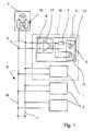
- Fig. 1 shows an embodiment of a fieldbus system according to the invention, wherein below - only for explanation and not restrictive - always an ASI system is mentioned.
- the ASI system has an ASI master 1, a plurality of ASI slaves 2, only two of which are shown here, an ASI power supply 3 and an ASI bus 4.
- the ASI master 1, the ASI slaves 2 and the AST power supply unit 3 are connected to one another via the ASI bus 4, the ASI power supply unit 3 supplying energy to the ASI slaves 2 and the ASI masters 1.
- the ASI power supply 3 provides a DC voltage of approx. 30 V at currents up to 8 A.
- the transmission of signals between the ASI master 1 and the ASI slaves 2 takes place via the ASI bus 4, for which purpose the signals are modulated by means of a special modulation method as AC voltage signals of the DC voltage.
- the ASI system also has a monitoring device 5, which is used in particular for detecting an incorrect addressing of an ASI slave 2 in the ASI system.
- the monitoring device 5 has a voltage detection unit 6, an impedance circuit 7 and an evaluation unit 8. Via the bus connection 9, the voltage detection unit 6 is connected to the ASI bus 4, so that the voltage detection unit 5 can tap the applied between the two conductors 10, 11 of the ASI bus 4 modulation voltage without feedback,
- the voltage detection unit 6 downstream impedance circuit 7 is formed so that its impedance to the impedance 12 of the ASI power supply 3 is adapted so that the current flowing through the impedance circuit 7 current I corresponds to the current flowing through the ASI bus 4 modulation current i.
- the evaluation unit 8 By the - only symbolically represented - current measurement 13 in the evaluation unit 8 is an addressing of two ASI slaves 2 with the same address easily detectable, including in particular the amplitude of the measured current I is evaluated and based on a threshold is determined whether the modulation current i and so that the current I has been caused by the slave response of an ASI slave 2 or by the superimposed slave responses of two ASI slaves 2 with the same address.
- the evaluation unit 8 preferably also carries out a voltage measurement 14 of the modulation voltage tapped by the voltage detection unit 6.
- Fig. 2 shows a preferred realization of the voltage detection unit 6 and the impedance circuit 7,
- the in Fig. 2 Simplified illustrated impedance circuit 7 consists of a here only symbolically shown parallel connection of at least one inductor 15 and a resistor 16.
- a separate power supply for the monitoring device 5 is thus not required, so that the monitoring device 5 can be connected while maintaining the Topologie scored easily via the bus terminal 9 to the ASI bus 4.
- the monitoring device 5 is connected in the vicinity of the ASI power supply 3 to the ASI bus 4, but it is not essential that the monitoring device 5 is connected immediately adjacent to the ASI power supply 3; it is also possible, for example, that the ASI master 1 and / or an ASI slave 2 is connected to the ASI bus 4 between the ASI power supply 3 and the monitoring device 5.
- the monitoring device 5 together with the ASI master 1 in an in Fig. 1 dashed shown common housing 19, so that a detected by the monitoring device 5 double addressing of two ASI slaves 2 is present directly in the ASI master 1, so that for example via the ASI master 1 independently reassignment of the ASI slaves 2 can be made.
- the presence of a double addressing can be visually and / or acoustically displayed via the ASI master 1.
Landscapes
- Physics & Mathematics (AREA)
- General Physics & Mathematics (AREA)
- Engineering & Computer Science (AREA)
- Automation & Control Theory (AREA)
- Small-Scale Networks (AREA)
Applications Claiming Priority (1)
| Application Number | Priority Date | Filing Date | Title |
|---|---|---|---|
| DE200710025852 DE102007025852B3 (de) | 2007-06-01 | 2007-06-01 | Überwachungseinrichtung zur Erkennung einer fehlerhaften Adressierung eines Aktuator-Sensor-Interface-Slaves |
Publications (3)
| Publication Number | Publication Date |
|---|---|
| EP2000866A2 true EP2000866A2 (fr) | 2008-12-10 |
| EP2000866A3 EP2000866A3 (fr) | 2009-12-16 |
| EP2000866B1 EP2000866B1 (fr) | 2017-03-01 |
Family
ID=39719816
Family Applications (1)
| Application Number | Title | Priority Date | Filing Date |
|---|---|---|---|
| EP08009811.4A Active EP2000866B1 (fr) | 2007-06-01 | 2008-05-29 | Dispositif de surveillance destiné à la reconnaissance d'un adressage incorrect d'un esclave dans un système de bus de terrain |
Country Status (2)
| Country | Link |
|---|---|
| EP (1) | EP2000866B1 (fr) |
| DE (1) | DE102007025852B3 (fr) |
Cited By (6)
| Publication number | Priority date | Publication date | Assignee | Title |
|---|---|---|---|---|
| EP2254011A1 (fr) * | 2009-05-20 | 2010-11-24 | Siemens Aktiengesellschaft | Alimentation en énergie d'une interface AS |
| EP2348374A1 (fr) | 2010-01-18 | 2011-07-27 | Siemens Aktiengesellschaft | Procédé de détection d'un adressage multiple défectueux d'un réseau fonctionnant selon le principe maître-esclave et un réseau à interface de capteur d'actionneur correspondant |
| DE102013216564A1 (de) | 2013-08-21 | 2015-02-26 | Ifm Electronic Gmbh | Verfahren zur Erkennung einer Doppeladressierung von Slaves in einem Master-Slave-Bussystem |
| CN107463130A (zh) * | 2017-08-16 | 2017-12-12 | 深圳市联赢激光股份有限公司 | 一种具有精准错误判别功能的级联电路 |
| CN109062113A (zh) * | 2018-09-03 | 2018-12-21 | 山海特种装备股份有限公司 | 一种飞机气源车电气控制装置 |
| CN119854267A (zh) * | 2025-03-18 | 2025-04-18 | 合肥智芯半导体有限公司 | 从机地址确定装置、方法、存储介质和电子设备 |
Families Citing this family (6)
| Publication number | Priority date | Publication date | Assignee | Title |
|---|---|---|---|---|
| DE102009033229B4 (de) * | 2009-07-14 | 2018-07-12 | Bihl+Wiedemann Gmbh | Verfahren zur Erkennung von Doppeladressierungen in AS Interface Netzen |
| DE102011101172A1 (de) | 2011-05-11 | 2012-11-15 | Andreas Schiff | Mehrfachadresserkennung in AS-Interface-Netzwerken |
| WO2013013710A1 (fr) | 2011-07-27 | 2013-01-31 | Siemens Aktiengesellschaft | Détection d'un adressage multiple défectueux à l'intérieur d'un système d'interface actionneur-capteur |
| DE102017128249B4 (de) | 2017-11-29 | 2022-02-17 | Ifm Electronic Gmbh | Anordnung für einen Aktuator-Sensor Interface Feldbus (AS-i-Bus) mit einem Diagnosegerät |
| DE102019104918B4 (de) * | 2019-02-27 | 2025-05-08 | Elmos Semiconductor Se | Verfahren zur Erkennung einer fehlerhaften Busknotenadresszuordnung in Datenbussystemen mit Autoadresszuweisung mittels eines Adresszuweisungsstroms |
| DE102022126354B3 (de) | 2022-10-11 | 2023-12-21 | Ifm Electronic Gmbh | Verfahren zur automatischen Adressvergabe in einem AS-I-Master-Slave-Bussystem |
Citations (1)
| Publication number | Priority date | Publication date | Assignee | Title |
|---|---|---|---|---|
| DE10253566A1 (de) | 2001-11-15 | 2003-05-28 | Bihl & Wiedemann Gmbh | Aktuator-Sensor-Interface-System sowie Verfahren zum Betreiben eines solchen |
Family Cites Families (4)
| Publication number | Priority date | Publication date | Assignee | Title |
|---|---|---|---|---|
| US4186339A (en) * | 1978-01-20 | 1980-01-29 | Curtis Instruments, Inc. | Method and apparatus for measuring current, especially useful in multi-ampere systems |
| DE4412653C2 (de) * | 1994-04-13 | 1997-01-09 | Schmersal K A Gmbh & Co | Überwachungseinrichtung |
| DE10104908A1 (de) * | 2001-02-03 | 2002-08-08 | Metrawatt Gmbh Gossen | Elektronische Vorrichtung zur Überwachung elektrisch erfaßbarer Zustände und/oder Größen von Bussystemen, Bus-Power-Monitor |
| DE10134538A1 (de) * | 2001-07-16 | 2003-02-13 | Siemens Ag | Überwachungsverfahren für ein Bussystem und hiermit korrespondierende Auswertungsschaltung |
-
2007
- 2007-06-01 DE DE200710025852 patent/DE102007025852B3/de active Active
-
2008
- 2008-05-29 EP EP08009811.4A patent/EP2000866B1/fr active Active
Patent Citations (1)
| Publication number | Priority date | Publication date | Assignee | Title |
|---|---|---|---|---|
| DE10253566A1 (de) | 2001-11-15 | 2003-05-28 | Bihl & Wiedemann Gmbh | Aktuator-Sensor-Interface-System sowie Verfahren zum Betreiben eines solchen |
Non-Patent Citations (5)
| Title |
|---|
| AS-INTERFACE DIE LÖSUNG IN DER AUTOMATION, pages 56 - 60 |
| AS-INTERFACE DIE LÖSUNG IN DER AUTOMATION, pages 62 - 65 |
| AS-INTERFACE DIE LÖSUNG IN DER AUTOMATION, pages 66 - 72 |
| ROLF BECKER: "AS-Interface Die Lösung in der Automation", AS-INTERNATIONAL ASSOCIATION, 2002 |
| ROLF BECKER: "AS-Interface Die Lösung in der Automation", AS-INTERNATIONAL ASSOCIATION, 2002, pages 14 - 17 |
Cited By (6)
| Publication number | Priority date | Publication date | Assignee | Title |
|---|---|---|---|---|
| EP2254011A1 (fr) * | 2009-05-20 | 2010-11-24 | Siemens Aktiengesellschaft | Alimentation en énergie d'une interface AS |
| EP2348374A1 (fr) | 2010-01-18 | 2011-07-27 | Siemens Aktiengesellschaft | Procédé de détection d'un adressage multiple défectueux d'un réseau fonctionnant selon le principe maître-esclave et un réseau à interface de capteur d'actionneur correspondant |
| DE102013216564A1 (de) | 2013-08-21 | 2015-02-26 | Ifm Electronic Gmbh | Verfahren zur Erkennung einer Doppeladressierung von Slaves in einem Master-Slave-Bussystem |
| CN107463130A (zh) * | 2017-08-16 | 2017-12-12 | 深圳市联赢激光股份有限公司 | 一种具有精准错误判别功能的级联电路 |
| CN109062113A (zh) * | 2018-09-03 | 2018-12-21 | 山海特种装备股份有限公司 | 一种飞机气源车电气控制装置 |
| CN119854267A (zh) * | 2025-03-18 | 2025-04-18 | 合肥智芯半导体有限公司 | 从机地址确定装置、方法、存储介质和电子设备 |
Also Published As
| Publication number | Publication date |
|---|---|
| EP2000866B1 (fr) | 2017-03-01 |
| DE102007025852B3 (de) | 2009-01-02 |
| EP2000866A3 (fr) | 2009-12-16 |
Similar Documents
| Publication | Publication Date | Title |
|---|---|---|
| EP2000866B1 (fr) | Dispositif de surveillance destiné à la reconnaissance d'un adressage incorrect d'un esclave dans un système de bus de terrain | |
| DE10392421B4 (de) | Handdiagnose- und kommunikationsgerät mit automatischer Buserkennung | |
| DE102014106752B4 (de) | Verfahren und Steuereinrichtung zum Betrieb eines berührungslosen Übertragungssystems für einen IO-Link | |
| EP3195525B1 (fr) | Bus d'entrée/sortie pour un système de bus | |
| EP3338404B1 (fr) | Système de bus | |
| EP2204014B1 (fr) | Procédé de communication et système maître-esclave pour un bus de champ de conception conforme à la norme d'interface actionneur-capteur | |
| EP3170287A1 (fr) | Système de commande et de transmission de données, module de passerelle, module e/a et procédé de commande de processus | |
| DE10112844C2 (de) | Verfahren und Vorrichtung zur Online-Prüfung von Feldbuseinrichtungen | |
| EP1312991A2 (fr) | Système d'interface actionneur capteur et procédé pour le commander | |
| EP3745217A1 (fr) | Procédé et dispositif de surveillance d'un système de traitement et de transmission de données. | |
| EP1687681A2 (fr) | Reseau, notamment reseau pa profibus, a proprietes de redondance, element de ramification pour appareil d'abonne dans un reseau de ce type, gestionnaire de redondance pour un reseau de ce type et procede pour faire fonctionner un reseau de ce type | |
| EP1999526A1 (fr) | Gestion d'un bus de terrain sans fil | |
| DE102005059012B4 (de) | ASI-Sytem zum Anschluß mehrerer Sensoren und/oder Aktuatoren an eine Steuerung | |
| DE102017213365B4 (de) | Kommunikationsvorrichtung, System und Verfahren | |
| EP1690390B1 (fr) | Procede de transmission de donnees via un bus de donnees, et systeme et passerelle permettant la mise en oeuvre dudit procede | |
| DE102019123146B4 (de) | Diagnose- und/oder parameterdaten-übertragung zwischen steuermodul und eingabe/ausgabe-modul | |
| DE102013216564A1 (de) | Verfahren zur Erkennung einer Doppeladressierung von Slaves in einem Master-Slave-Bussystem | |
| EP2778811A1 (fr) | Dispositif pour un système d'interface AS | |
| EP2209249B1 (fr) | Procédé d'évaluation de la qualité du signal dans un réseau doté de signaux à codage de Manchester à l'aide d'un diagramme de l'oeil | |
| EP1672446B1 (fr) | Module d'entrée/sortie sécurisé pour un controleur | |
| EP3632049B1 (fr) | Émission de signal d'état | |
| DE102010062670B4 (de) | Wartungseinheit für ein ASI-Bussystem sowie ASI-Bussystem | |
| EP2348374B1 (fr) | Procédé de détection d'un adressage multiple défectueux d'un réseau fonctionnant selon le principe maître-esclave et un réseau à interface de capteur d'actionneur correspondant | |
| DE102007029553B4 (de) | Verfahren zur Beurteilung der Übertragungsqualität der Kommunikation in einem Bussystem | |
| DE102019116657A1 (de) | System und Verfahren zur kombinierten Energieübertragung und Datenübertragung in einem Automatisierungssystem |
Legal Events
| Date | Code | Title | Description |
|---|---|---|---|
| PUAI | Public reference made under article 153(3) epc to a published international application that has entered the european phase |
Free format text: ORIGINAL CODE: 0009012 |
|
| AK | Designated contracting states |
Kind code of ref document: A2 Designated state(s): AT BE BG CH CY CZ DE DK EE ES FI FR GB GR HR HU IE IS IT LI LT LU LV MC MT NL NO PL PT RO SE SI SK TR |
|
| AX | Request for extension of the european patent |
Extension state: AL BA MK RS |
|
| PUAL | Search report despatched |
Free format text: ORIGINAL CODE: 0009013 |
|
| AK | Designated contracting states |
Kind code of ref document: A3 Designated state(s): AT BE BG CH CY CZ DE DK EE ES FI FR GB GR HR HU IE IS IT LI LT LU LV MC MT NL NO PL PT RO SE SI SK TR |
|
| AX | Request for extension of the european patent |
Extension state: AL BA MK RS |
|
| 17P | Request for examination filed |
Effective date: 20100601 |
|
| 17Q | First examination report despatched |
Effective date: 20100630 |
|
| AKX | Designation fees paid |
Designated state(s): DE FR GB |
|
| RAP1 | Party data changed (applicant data changed or rights of an application transferred) |
Owner name: IFM ELECTRONIC GMBH |
|
| GRAP | Despatch of communication of intention to grant a patent |
Free format text: ORIGINAL CODE: EPIDOSNIGR1 |
|
| INTG | Intention to grant announced |
Effective date: 20160909 |
|
| GRAS | Grant fee paid |
Free format text: ORIGINAL CODE: EPIDOSNIGR3 |
|
| GRAA | (expected) grant |
Free format text: ORIGINAL CODE: 0009210 |
|
| AK | Designated contracting states |
Kind code of ref document: B1 Designated state(s): DE FR GB |
|
| REG | Reference to a national code |
Ref country code: GB Ref legal event code: FG4D Free format text: NOT ENGLISH |
|
| REG | Reference to a national code |
Ref country code: DE Ref legal event code: R096 Ref document number: 502008015054 Country of ref document: DE |
|
| REG | Reference to a national code |
Ref country code: FR Ref legal event code: PLFP Year of fee payment: 10 |
|
| REG | Reference to a national code |
Ref country code: DE Ref legal event code: R097 Ref document number: 502008015054 Country of ref document: DE |
|
| PLBE | No opposition filed within time limit |
Free format text: ORIGINAL CODE: 0009261 |
|
| STAA | Information on the status of an ep patent application or granted ep patent |
Free format text: STATUS: NO OPPOSITION FILED WITHIN TIME LIMIT |
|
| 26N | No opposition filed |
Effective date: 20171204 |
|
| REG | Reference to a national code |
Ref country code: FR Ref legal event code: PLFP Year of fee payment: 11 |
|
| REG | Reference to a national code |
Ref country code: DE Ref legal event code: R084 Ref document number: 502008015054 Country of ref document: DE |
|
| PGFP | Annual fee paid to national office [announced via postgrant information from national office to epo] |
Ref country code: DE Payment date: 20250519 Year of fee payment: 18 |
|
| PGFP | Annual fee paid to national office [announced via postgrant information from national office to epo] |
Ref country code: GB Payment date: 20250522 Year of fee payment: 18 |
|
| PGFP | Annual fee paid to national office [announced via postgrant information from national office to epo] |
Ref country code: FR Payment date: 20250521 Year of fee payment: 18 |