EP2001145A9 - Dispositif de station de base et procédé de détection d'erreur d'installation de dispositif de station de base - Google Patents
Dispositif de station de base et procédé de détection d'erreur d'installation de dispositif de station de base Download PDFInfo
- Publication number
- EP2001145A9 EP2001145A9 EP07739419A EP07739419A EP2001145A9 EP 2001145 A9 EP2001145 A9 EP 2001145A9 EP 07739419 A EP07739419 A EP 07739419A EP 07739419 A EP07739419 A EP 07739419A EP 2001145 A9 EP2001145 A9 EP 2001145A9
- Authority
- EP
- European Patent Office
- Prior art keywords
- installation direction
- base station
- station device
- inclination
- installation
- Prior art date
- Legal status (The legal status is an assumption and is not a legal conclusion. Google has not performed a legal analysis and makes no representation as to the accuracy of the status listed.)
- Granted
Links
Images

Classifications
-
- H—ELECTRICITY
- H04—ELECTRIC COMMUNICATION TECHNIQUE
- H04W—WIRELESS COMMUNICATION NETWORKS
- H04W24/00—Supervisory, monitoring or testing arrangements
-
- H—ELECTRICITY
- H01—ELECTRIC ELEMENTS
- H01Q—ANTENNAS, i.e. RADIO AERIALS
- H01Q1/00—Details of, or arrangements associated with, antennas
- H01Q1/12—Supports; Mounting means
- H01Q1/125—Means for positioning
-
- H—ELECTRICITY
- H01—ELECTRIC ELEMENTS
- H01Q—ANTENNAS, i.e. RADIO AERIALS
- H01Q1/00—Details of, or arrangements associated with, antennas
- H01Q1/12—Supports; Mounting means
- H01Q1/22—Supports; Mounting means by structural association with other equipment or articles
- H01Q1/24—Supports; Mounting means by structural association with other equipment or articles with receiving set
- H01Q1/241—Supports; Mounting means by structural association with other equipment or articles with receiving set used in mobile communications, e.g. GSM
- H01Q1/246—Supports; Mounting means by structural association with other equipment or articles with receiving set used in mobile communications, e.g. GSM specially adapted for base stations
-
- H—ELECTRICITY
- H01—ELECTRIC ELEMENTS
- H01Q—ANTENNAS, i.e. RADIO AERIALS
- H01Q1/00—Details of, or arrangements associated with, antennas
- H01Q1/42—Housings not intimately mechanically associated with radiating elements, e.g. radome
-
- H—ELECTRICITY
- H04—ELECTRIC COMMUNICATION TECHNIQUE
- H04W—WIRELESS COMMUNICATION NETWORKS
- H04W88/00—Devices specially adapted for wireless communication networks, e.g. terminals, base stations or access point devices
- H04W88/08—Access point devices
Definitions
- the present invention relates to a base station device and a base station device installation error detection method.
- compact, lightweight, and low-level-output base station devices for the personal handy-phone system (PHS) and the like are installed on electric poles, ceilings in train stations, or roofs of buildings. Further, in many cases, the base station devices are enclosed in a chassis to protect the base station devices from water such as rain and snow.
- Patent Document 1 discloses a technique for a mobile telephone set having an Internet connecting function and an email sending and receiving function.
- the mobile telephone set includes means of one or more types for detecting an abnormal situation or an emergency situation, and receives and sends information on the detected abnormal situation or emergency situation.
- the above-mentioned conventional base station devices may be unable to perform usual communications if the base station devices are installed in a direction different from a normal installation direction. For example, if such a base station device is installed at a wrong angle, the angle of an antenna element connected to the base station device shifts, changing the area covered by the base station device or degrading its communication characteristics in some cases. Further, even when the base station device is enclosed in a chassis, if the base station device is installed with a joint part facing upward, water such as rain may enter the base station device to cause a malfunction or an explosion at worst.
- the present invention has been made, and therefore, it is an object of the present invention to provide a base station device and a base station device installation error detection method, capable of preventing an error in direction of installation.
- a base station device includes: reference installation direction storage means for storing at least one reference installation direction serving as a reference installation direction for the base station device; installation direction measuring means for measuring an installation direction of the base station device; inclination judgment means for calculating inclination angles each defined by each reference installation direction stored in the reference installation direction storage means and the installation direction measured by the installation direction measuring means, and for judging whether each of the inclination angles exceeds a predetermined value; and installation error alarm means for issuing a predetermined alarm when the inclination judgment means judges that some or all of the inclination angles exceed the predetermined value.
- a base station device installation error detection method includes: a step of storing at least one reference installation direction serving as a reference installation direction for a base station device, in reference installation direction storage means; an installation direction measuring step of measuring an installation direction of the base station device; an inclination judgment step of calculating inclination angles each defined by each reference installation direction stored in the reference installation direction storage means and the installation direction measured in the installation direction measuring step, and of judging whether each of the inclination angles exceeds a predetermined value; and an installation error alarm step of issuing a predetermined alarm when it is judged, in the inclination judgment step, that some or all of the inclination angles exceed the predetermined value.
- At least one reference installation direction serving as a reference installation direction for the base station device is stored in the base station device, and the installation direction of the base station device is measured.
- inclination angles each defined by each stored reference installation direction and the measured installation direction is calculated, respectively. It is judged whether each of the inclination angles exceeds a predetermined value.
- a predetermined alarm is issued. According to the present invention, an alarm is issued when the base station device is installed in a direction different from a normal installation direction (reference installation direction) stored in advance in the base station device, and hence an error in direction of installation can be prevented.
- the installation direction is a direction of gravity acceleration with respect to the base station device. Therefore, the inclination angle of the base station device can be calculated based on a shift of the direction of gravity acceleration viewed from the base station device.
- FIG. 1 is a functional block diagram of a base station device 10.
- the base station device 10 includes a control unit 20, a radio communication unit 30, a line interface 40, and an installation direction check unit 50.
- the base station device 10 is installed on an electric pole, a ceiling in a train station, or a roof of a building, in many cases, and has one or more normal installation directions. Further, the base station device 10 is enclosed in a chassis to protect the base station device 10 from water such as rain and snow.
- the control unit 20 includes an operation management unit 22, a radio control unit 24, and a line control unit 26, and is configured by a CPU, a memory, and the like.
- the operation management unit 22 is connected to the radio control unit 24, the line control unit 26, the installation direction check unit 50, and the like to control the entire operation of the base station device 10.
- the radio control unit 24 is connected to the radio communication unit 30 to control the radio communication unit 30 according to an instruction of the operation management unit 22.
- the line control unit 26 is connected to the line interface 40 to control the line interface 40 according to the instruction of the operation management unit 22.
- the radio communication unit 30 includes an antenna 32, and is connected to the radio control unit 24 and also to the line interface 40 via the control unit 20.
- the radio communication unit 30 demodulates, according to an instruction of the radio control unit 24, a signal sent from each communication device and received by the antenna 32, separates and extracts packets from the signal, and outputs the packets to the line interface 40 via the control unit 20. Further, the radio communication unit 30 multiplexs and modulates multiple packets input from the line interface 40 via the control unit 20 and sends a modulated signal to each communication device via the antenna 32.
- the line interface 40 is connected to the line control unit 26 and also to the radio communication unit 30 via the control unit 20, and links the base station device 10 and a communication network mutually.
- the line interface 40 outputs packets input from the communication network to the radio communication unit 30 via the control unit 20 according to the instruction of the line control unit 26. Further, the line interface 40 outputs multiple packets input from the radio communication unit 30 via the control unit 20 to the communication network.
- the installation direction check unit 50 includes an acceleration sensor (installation direction measuring unit) 52, a reference installation direction storage unit 54, an inclination judgment unit 56, and an installation error alarm unit 58.
- the installation direction check unit 50 calculates the inclination angle of the base station device 10 with respect to a normal installation direction, and issues a predetermined alarm when the calculated inclination angle exceeds a predetermined value.
- the acceleration sensor 52 measures the magnitude of acceleration applied to the object in which the acceleration sensor 52 is installed.
- the acceleration sensor 52 can measure the magnitude and direction of gravity acceleration (gravity acceleration vector) to obtain the x-, y-, and z-direction components of the gravity acceleration vector in a coordinate system in which the acceleration sensor 52 serves as a reference.
- the acceleration sensor 52 is fixed to the base station device 10 and measures each component of the gravity acceleration vector as the installation direction of the base station device 10.
- the average value of gravity acceleration vectors measured at predetermined sampling intervals for a predetermined period of time may be used as the gravity acceleration vector.
- a measurement value of the acceleration sensor 52 is output to the inclination judgment unit 56. In the inclination judgment unit 56, the inclination angle of the base station device 10 is calculated based on the measurement value, as described later.
- the reference installation direction storage unit 54 stores at least one reference installation direction of the base station device 10, in other words, at least one reference installation direction serving as a normal installation direction of the base station device 10.
- the reference installation direction is expressed by the x-, y-, and z-direction components of the gravity acceleration vector obtained when the base station device 10 is installed in the normal installation direction.
- the gravity acceleration vector is measured by the acceleration sensor 52 when the base station device 10 is installed in the normal installation direction, and the x-, y-, and z-direction components thereof are stored in the reference installation direction storage unit 54 as a reference installation direction.
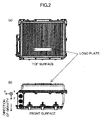
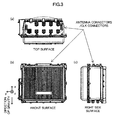
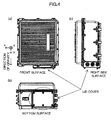
- FIGS. 2 to 4 are views illustrating appearances of the base station device 10 and normal installation directions.
- FIGS. 2 illustrate a state where the base station device 10 is installed such that the logo plate of the base station device 10 faces upward.
- FIGS. 2(a) and 2(b) correspond to a top view of the base station device 10 and a front view thereof, respectively.
- the x, y, and z directions for the base station device 10 are defined as the rearward direction, the leftward direction, and the downward direction of the base station device 10, respectively, in the front view of FIG. 2(b) (the same applies to FIGS. 3 and 4 ). Since the gravity acceleration vector has the downward direction in the front view of FIG.
- FIGS. 3 illustrate a state where the base station device 10 is installed such that antenna connectors/CLK connectors of the base station device 10 face upward.
- the inclination judgment unit 56 judges whether the installation direction of the base station device 10 matches some or all of reference installation directions stored in the reference installation direction storage unit 54. Specifically, the inclination judgment unit 56 calculates the inclination angles each defined by each of the reference installation directions stored in the reference installation direction storage unit 54 and the installation direction measured by the acceleration sensor 52.
- the inclination angle is expressed by ⁇
- the reference installation direction is expressed by (x0,y0,z0)
- the installation direction measured by the acceleration sensor 52 is expressed by (x,y,z)
- the inclination angle ⁇ is obtained by the following formula.
- the inclination judgment unit 56 judges whether each inclination angle calculated by the above-mentioned formula exceeds a threshold. Since the threshold is a value indicating an acceptable range for the inclination angle, when the threshold is set to a smaller value, the base station device 10 has to be installed in a more accurate direction.
- the installation error alarm unit 58 issues a predetermined alarm when the inclination judgment unit 56 judges that some or all of inclination angles exceed the threshold, in other words, judges that the shift from the normal installation direction is large. For example, when only one installation direction illustrated in FIGS. 2 is stored in the reference installation direction storage unit 54 as a reference installation direction and the threshold is set to a small value, if the base station device 10 is installed in a direction different from the normal installation direction illustrated in FIGS. 3 , an alarm is issued so as to prevent an error in direction of installation. Further, it is also possible that three installation directions illustrated in FIGS.
- the installation error alarm unit 58 issues an alarm only when all of three inclination angles each calculated by the inclination judgment unit 56 for each of the reference installation directions exceed the threshold. Therefore, an alarm is issued only when the base station device 10 is installed in a direction different from all of the installation directions illustrated in FIGS. 2 to 4 .
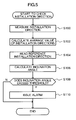
- the process is performed to check whether the base station device 10 has been installed in a normal installation direction, and is usually activated with a button operation or the like by a worker who has installed the base station device 10 at the completion of installation.
- the acceleration sensor 52 measures an installation direction (gravity acceleration vector) at predetermined sampling intervals for a predetermined period of time (S100).
- the inclination judgment unit 56 calculates the average value of multiple installation directions measured by the acceleration sensor 52, in order to reduce an error in measurement (S102).
- One or more reference installation directions each expressed by the gravity acceleration vector are read from the reference installation direction storage unit 54 (S104).
- the inclination judgment unit 56 calculates the inclination angles each defined by each of the reference installation directions read in S104 and the installation direction obtained in S102 (S106), and judges whether each inclination angle exceeds a threshold (S108).
- a threshold S108
- the installation error alarm unit 58 issues a predetermined alarm (S110), and the process ends.
- the process ends without issuing the alarm.
- the acceleration sensor is used to measure the installation direction of the base station device in the embodiment, but any types of sensors (for example, a geomagnetic sensor) which can obtain information indicating a direction may be used instead of the acceleration sensor.
Landscapes
- Engineering & Computer Science (AREA)
- Computer Networks & Wireless Communication (AREA)
- Signal Processing (AREA)
- Mobile Radio Communication Systems (AREA)
Applications Claiming Priority (2)
| Application Number | Priority Date | Filing Date | Title |
|---|---|---|---|
| JP2006089442A JP5118816B2 (ja) | 2006-03-28 | 2006-03-28 | 基地局装置及び基地局装置の設置誤り検出方法 |
| PCT/JP2007/055978 WO2007116645A1 (fr) | 2006-03-28 | 2007-03-23 | Dispositif de station de base et procédé de détection d'erreur d'installation de dispositif de station de base |
Publications (4)
| Publication Number | Publication Date |
|---|---|
| EP2001145A2 EP2001145A2 (fr) | 2008-12-10 |
| EP2001145A9 true EP2001145A9 (fr) | 2009-03-25 |
| EP2001145A4 EP2001145A4 (fr) | 2009-12-16 |
| EP2001145B1 EP2001145B1 (fr) | 2015-05-27 |
Family
ID=38580944
Family Applications (1)
| Application Number | Title | Priority Date | Filing Date |
|---|---|---|---|
| EP07739419.5A Not-in-force EP2001145B1 (fr) | 2006-03-28 | 2007-03-23 | Dispositif de station de base et procédé de détection d'erreur d'installation de dispositif de station de base |
Country Status (6)
| Country | Link |
|---|---|
| US (1) | US8060146B2 (fr) |
| EP (1) | EP2001145B1 (fr) |
| JP (1) | JP5118816B2 (fr) |
| KR (1) | KR100998811B1 (fr) |
| CN (1) | CN101405967A (fr) |
| WO (1) | WO2007116645A1 (fr) |
Families Citing this family (13)
| Publication number | Priority date | Publication date | Assignee | Title |
|---|---|---|---|---|
| JP4654148B2 (ja) * | 2006-03-28 | 2011-03-16 | 京セラ株式会社 | 基地局装置及び基地局装置の傾斜測定方法 |
| EP2113896B1 (fr) * | 2008-04-29 | 2013-10-16 | RADIO SYSTEMES INGENIERIE VIDEO TECHNOLOGIES (Société Anonyme) | Unité de détection protégée contre l'arrachement et/ou l'effraction et système comprenant au moins une telle unité |
| WO2010106439A2 (fr) * | 2009-03-16 | 2010-09-23 | Le Sage Hendrikus A | Système détecteur d'inclinaison en ligne aisg et procédé associé |
| DE102010024932A1 (de) | 2010-06-24 | 2011-12-29 | N.Log Gmbh | Meßsystem zur Belastungsüberwachung von Großstrukturen |
| EP2883272B1 (fr) | 2013-08-27 | 2016-06-15 | CommScope Technologies LLC | Détermination d'alignement pour antennes |
| US9942749B2 (en) * | 2015-10-26 | 2018-04-10 | Time Warner Cable Enterprises Llc | Methods and apparatus for managing and/or configuring base stations which include sensors |
| WO2017192714A1 (fr) * | 2016-05-04 | 2017-11-09 | Commscope Technologies Llc | Système et procédé de réglage de faisceau d'antenne sur un pylône d'antenne |
| CN107864330B (zh) * | 2016-09-22 | 2020-06-16 | 光宝电子(广州)有限公司 | 摄像机及其设定方法与调整方法 |
| JP7395382B2 (ja) * | 2020-02-18 | 2023-12-11 | 東京計器株式会社 | 基地局装置 |
| CN115812329B (zh) * | 2020-07-08 | 2025-09-23 | 诺基亚技术有限公司 | 校准波束取向误差以改进定位 |
| WO2022137441A1 (fr) * | 2020-12-24 | 2022-06-30 | 日本電信電話株式会社 | Dispositif de radiocommunication et procédé de commande |
| CN112762913B (zh) * | 2021-01-12 | 2022-06-10 | 国网浙江省电力有限公司湖州供电公司 | 一种基于电子指南针技术的砼杆调整装置 |
| CN116753912A (zh) * | 2023-08-21 | 2023-09-15 | 常安城市公共安全技术有限公司 | 可燃气体监测装置的安装方法 |
Family Cites Families (15)
| Publication number | Priority date | Publication date | Assignee | Title |
|---|---|---|---|---|
| US3739364A (en) * | 1971-06-07 | 1973-06-12 | Texas Instruments Inc | Antenna mast misalignment detector |
| JPH07273518A (ja) | 1994-03-28 | 1995-10-20 | Nippon Telegr & Teleph Corp <Ntt> | アンテナ転倒警報機 |
| JP3349351B2 (ja) | 1996-07-08 | 2002-11-25 | 三洋電機株式会社 | 携帯電話機の基地局ユニット |
| JP2000278023A (ja) | 1999-03-26 | 2000-10-06 | Ishikawajima Harima Heavy Ind Co Ltd | アンテナ制御装置及びそのためのプログラム記録媒体 |
| US6239744B1 (en) * | 1999-06-30 | 2001-05-29 | Radio Frequency Systems, Inc. | Remote tilt antenna system |
| US6606075B1 (en) * | 2001-06-07 | 2003-08-12 | Luxul Corporation | Modular wireless broadband antenna tower |
| US6864847B2 (en) * | 2002-02-22 | 2005-03-08 | Jan Blair Wensink | System for remotely adjusting antennas |
| CA2426928C (fr) * | 2002-04-30 | 2007-12-04 | Christian Boucher | Systeme d'alignement d'antenne |
| US7155216B2 (en) * | 2002-09-19 | 2006-12-26 | Nokia Corporation | Functionality test in a base transceiver station |
| KR100585834B1 (ko) * | 2003-03-21 | 2006-06-01 | 에스케이 텔레콤주식회사 | 무선통신 기지국 안테나의 재원 측정 및 교정 방법과 그시스템 |
| JP2005024668A (ja) * | 2003-06-30 | 2005-01-27 | Sharp Corp | 投映型表示装置及び該投映型表示装置の設置調整方法 |
| DE20311407U1 (de) * | 2003-07-24 | 2003-09-11 | EuBUS GmbH, 82343 Pöcking | Vorrichtung zur Überprüfung der Ausrichtung einer Antennenanlage |
| JP4339673B2 (ja) * | 2003-12-19 | 2009-10-07 | 京セラ株式会社 | 携帯端末装置、通信システム、及び無線装置における撮像制御方法 |
| JP2005311995A (ja) | 2004-04-16 | 2005-11-04 | Taitaro Fujii | 異常・緊急事態検知手段としての携帯電話機 |
| US20070229378A1 (en) * | 2006-03-17 | 2007-10-04 | Steve Clark | Telecommunications antenna monitoring system |
-
2006
- 2006-03-28 JP JP2006089442A patent/JP5118816B2/ja not_active Expired - Fee Related
-
2007
- 2007-03-23 EP EP07739419.5A patent/EP2001145B1/fr not_active Not-in-force
- 2007-03-23 WO PCT/JP2007/055978 patent/WO2007116645A1/fr not_active Ceased
- 2007-03-23 CN CNA2007800098559A patent/CN101405967A/zh active Pending
- 2007-03-23 US US12/294,607 patent/US8060146B2/en not_active Expired - Fee Related
- 2007-03-23 KR KR1020087023170A patent/KR100998811B1/ko not_active Expired - Fee Related
Also Published As
| Publication number | Publication date |
|---|---|
| US8060146B2 (en) | 2011-11-15 |
| KR20080096599A (ko) | 2008-10-30 |
| JP5118816B2 (ja) | 2013-01-16 |
| CN101405967A (zh) | 2009-04-08 |
| US20090233645A1 (en) | 2009-09-17 |
| EP2001145A2 (fr) | 2008-12-10 |
| EP2001145B1 (fr) | 2015-05-27 |
| EP2001145A4 (fr) | 2009-12-16 |
| JP2007267023A (ja) | 2007-10-11 |
| KR100998811B1 (ko) | 2010-12-06 |
| WO2007116645A1 (fr) | 2007-10-18 |
Similar Documents
| Publication | Publication Date | Title |
|---|---|---|
| EP2001145B1 (fr) | Dispositif de station de base et procédé de détection d'erreur d'installation de dispositif de station de base | |
| US6377165B1 (en) | Mayday system equipment and mayday system | |
| EP1873548A1 (fr) | Système de détermination de position et procédé de détermination de position | |
| JP2002039751A (ja) | 高さ位置を決定する通信機器と通信機器の高さを決定する方法 | |
| US11022721B2 (en) | Spatially diverse snowpack sensing system | |
| AU2021323937A1 (en) | Tracking device and system | |
| US20160323439A1 (en) | Mobile electronic device, control method, and storage medium | |
| US7239883B2 (en) | Emergency calling with a GSM radiotelephone | |
| CN107720467A (zh) | 电梯定位方法、装置及存储介质 | |
| US7398092B2 (en) | Location tracing system for mobile telecommunication terminal and method thereof | |
| EP1720037B1 (fr) | Appareil et procédé d'estimation d'emplacement | |
| US20160316344A1 (en) | Mobile electronic device, control method, and storage medium | |
| ITMO20090251A1 (it) | Apparecchiatura telematica per veicoli | |
| KR100782546B1 (ko) | 광역 비상송수신 복합시스템 | |
| JP2004045274A (ja) | 無線通信機能付移動端末、基地局及び無線通信システム | |
| JP4727448B2 (ja) | 震災情報提供システム、地震監視局及び基地局 | |
| JPH0836044A (ja) | 携帯電話システムを利用したgps装置 | |
| JP4734997B2 (ja) | 携帯端末装置、携帯端末システム、キャリブレーション方法 | |
| JP4654148B2 (ja) | 基地局装置及び基地局装置の傾斜測定方法 | |
| JP2002107444A (ja) | 位置検出制御装置 | |
| EP1163814B1 (fr) | Station mobile comprenant plusieurs interfaces | |
| JPH1196465A (ja) | 盗難防止端末機 | |
| CN118629152A (zh) | 一种重物坠落预警装置及方法 | |
| KR100999664B1 (ko) | 어린이 보호 알림 장치 및 방법 | |
| CN120710557A (zh) | 集成安全帽的卫星通信终端及信号处理算法 |
Legal Events
| Date | Code | Title | Description |
|---|---|---|---|
| PUAI | Public reference made under article 153(3) epc to a published international application that has entered the european phase |
Free format text: ORIGINAL CODE: 0009012 |
|
| 17P | Request for examination filed |
Effective date: 20080926 |
|
| AK | Designated contracting states |
Kind code of ref document: A2 Designated state(s): AT BE BG CH CY CZ DE DK EE ES FI FR GB GR HU IE IS IT LI LT LU LV MC MT NL PL PT RO SE SI SK TR |
|
| PUAB | Information related to the publication of an a document modified or deleted |
Free format text: ORIGINAL CODE: 0009199EPPU |
|
| A4 | Supplementary search report drawn up and despatched |
Effective date: 20091117 |
|
| RIC1 | Information provided on ipc code assigned before grant |
Ipc: H01Q 1/12 20060101AFI20091111BHEP |
|
| 17Q | First examination report despatched |
Effective date: 20110607 |
|
| DAX | Request for extension of the european patent (deleted) | ||
| GRAP | Despatch of communication of intention to grant a patent |
Free format text: ORIGINAL CODE: EPIDOSNIGR1 |
|
| RIC1 | Information provided on ipc code assigned before grant |
Ipc: H01Q 1/12 20060101AFI20141121BHEP Ipc: H01Q 1/42 20060101ALI20141121BHEP Ipc: H01Q 1/24 20060101ALI20141121BHEP Ipc: H04W 88/08 20090101ALN20141121BHEP Ipc: H04W 24/00 20090101ALI20141121BHEP |
|
| INTG | Intention to grant announced |
Effective date: 20141209 |
|
| GRAS | Grant fee paid |
Free format text: ORIGINAL CODE: EPIDOSNIGR3 |
|
| GRAA | (expected) grant |
Free format text: ORIGINAL CODE: 0009210 |
|
| AK | Designated contracting states |
Kind code of ref document: B1 Designated state(s): AT BE BG CH CY CZ DE DK EE ES FI FR GB GR HU IE IS IT LI LT LU LV MC MT NL PL PT RO SE SI SK TR |
|
| REG | Reference to a national code |
Ref country code: GB Ref legal event code: FG4D |
|
| REG | Reference to a national code |
Ref country code: CH Ref legal event code: EP |
|
| REG | Reference to a national code |
Ref country code: AT Ref legal event code: REF Ref document number: 729275 Country of ref document: AT Kind code of ref document: T Effective date: 20150615 |
|
| REG | Reference to a national code |
Ref country code: IE Ref legal event code: FG4D |
|
| REG | Reference to a national code |
Ref country code: DE Ref legal event code: R096 Ref document number: 602007041575 Country of ref document: DE |
|
| REG | Reference to a national code |
Ref country code: AT Ref legal event code: MK05 Ref document number: 729275 Country of ref document: AT Kind code of ref document: T Effective date: 20150527 |
|
| REG | Reference to a national code |
Ref country code: LT Ref legal event code: MG4D |
|
| PG25 | Lapsed in a contracting state [announced via postgrant information from national office to epo] |
Ref country code: LT Free format text: LAPSE BECAUSE OF FAILURE TO SUBMIT A TRANSLATION OF THE DESCRIPTION OR TO PAY THE FEE WITHIN THE PRESCRIBED TIME-LIMIT Effective date: 20150527 Ref country code: ES Free format text: LAPSE BECAUSE OF FAILURE TO SUBMIT A TRANSLATION OF THE DESCRIPTION OR TO PAY THE FEE WITHIN THE PRESCRIBED TIME-LIMIT Effective date: 20150527 Ref country code: FI Free format text: LAPSE BECAUSE OF FAILURE TO SUBMIT A TRANSLATION OF THE DESCRIPTION OR TO PAY THE FEE WITHIN THE PRESCRIBED TIME-LIMIT Effective date: 20150527 Ref country code: PT Free format text: LAPSE BECAUSE OF FAILURE TO SUBMIT A TRANSLATION OF THE DESCRIPTION OR TO PAY THE FEE WITHIN THE PRESCRIBED TIME-LIMIT Effective date: 20150928 |
|
| REG | Reference to a national code |
Ref country code: NL Ref legal event code: MP Effective date: 20150527 |
|
| PG25 | Lapsed in a contracting state [announced via postgrant information from national office to epo] |
Ref country code: BG Free format text: LAPSE BECAUSE OF FAILURE TO SUBMIT A TRANSLATION OF THE DESCRIPTION OR TO PAY THE FEE WITHIN THE PRESCRIBED TIME-LIMIT Effective date: 20150827 Ref country code: IS Free format text: LAPSE BECAUSE OF FAILURE TO SUBMIT A TRANSLATION OF THE DESCRIPTION OR TO PAY THE FEE WITHIN THE PRESCRIBED TIME-LIMIT Effective date: 20150927 Ref country code: LV Free format text: LAPSE BECAUSE OF FAILURE TO SUBMIT A TRANSLATION OF THE DESCRIPTION OR TO PAY THE FEE WITHIN THE PRESCRIBED TIME-LIMIT Effective date: 20150527 Ref country code: AT Free format text: LAPSE BECAUSE OF FAILURE TO SUBMIT A TRANSLATION OF THE DESCRIPTION OR TO PAY THE FEE WITHIN THE PRESCRIBED TIME-LIMIT Effective date: 20150527 Ref country code: GR Free format text: LAPSE BECAUSE OF FAILURE TO SUBMIT A TRANSLATION OF THE DESCRIPTION OR TO PAY THE FEE WITHIN THE PRESCRIBED TIME-LIMIT Effective date: 20150828 |
|
| PG25 | Lapsed in a contracting state [announced via postgrant information from national office to epo] |
Ref country code: DK Free format text: LAPSE BECAUSE OF FAILURE TO SUBMIT A TRANSLATION OF THE DESCRIPTION OR TO PAY THE FEE WITHIN THE PRESCRIBED TIME-LIMIT Effective date: 20150527 Ref country code: EE Free format text: LAPSE BECAUSE OF FAILURE TO SUBMIT A TRANSLATION OF THE DESCRIPTION OR TO PAY THE FEE WITHIN THE PRESCRIBED TIME-LIMIT Effective date: 20150527 |
|
| REG | Reference to a national code |
Ref country code: FR Ref legal event code: PLFP Year of fee payment: 10 |
|
| PG25 | Lapsed in a contracting state [announced via postgrant information from national office to epo] |
Ref country code: CZ Free format text: LAPSE BECAUSE OF FAILURE TO SUBMIT A TRANSLATION OF THE DESCRIPTION OR TO PAY THE FEE WITHIN THE PRESCRIBED TIME-LIMIT Effective date: 20150527 Ref country code: RO Free format text: LAPSE BECAUSE OF NON-PAYMENT OF DUE FEES Effective date: 20150527 Ref country code: PL Free format text: LAPSE BECAUSE OF FAILURE TO SUBMIT A TRANSLATION OF THE DESCRIPTION OR TO PAY THE FEE WITHIN THE PRESCRIBED TIME-LIMIT Effective date: 20150527 Ref country code: SK Free format text: LAPSE BECAUSE OF FAILURE TO SUBMIT A TRANSLATION OF THE DESCRIPTION OR TO PAY THE FEE WITHIN THE PRESCRIBED TIME-LIMIT Effective date: 20150527 |
|
| REG | Reference to a national code |
Ref country code: DE Ref legal event code: R097 Ref document number: 602007041575 Country of ref document: DE |
|
| PLBE | No opposition filed within time limit |
Free format text: ORIGINAL CODE: 0009261 |
|
| STAA | Information on the status of an ep patent application or granted ep patent |
Free format text: STATUS: NO OPPOSITION FILED WITHIN TIME LIMIT |
|
| PG25 | Lapsed in a contracting state [announced via postgrant information from national office to epo] |
Ref country code: IT Free format text: LAPSE BECAUSE OF FAILURE TO SUBMIT A TRANSLATION OF THE DESCRIPTION OR TO PAY THE FEE WITHIN THE PRESCRIBED TIME-LIMIT Effective date: 20150527 |
|
| 26N | No opposition filed |
Effective date: 20160301 |
|
| PG25 | Lapsed in a contracting state [announced via postgrant information from national office to epo] |
Ref country code: SI Free format text: LAPSE BECAUSE OF FAILURE TO SUBMIT A TRANSLATION OF THE DESCRIPTION OR TO PAY THE FEE WITHIN THE PRESCRIBED TIME-LIMIT Effective date: 20150527 |
|
| REG | Reference to a national code |
Ref country code: DE Ref legal event code: R082 Representative=s name: VIERING, JENTSCHURA & PARTNER MBB PATENT- UND , DE Ref document number: 602007041575 Country of ref document: DE |
|
| REG | Reference to a national code |
Ref country code: DE Ref legal event code: R082 Ref document number: 602007041575 Country of ref document: DE Representative=s name: VIERING, JENTSCHURA & PARTNER MBB PATENT- UND , DE |
|
| PG25 | Lapsed in a contracting state [announced via postgrant information from national office to epo] |
Ref country code: BE Free format text: LAPSE BECAUSE OF FAILURE TO SUBMIT A TRANSLATION OF THE DESCRIPTION OR TO PAY THE FEE WITHIN THE PRESCRIBED TIME-LIMIT Effective date: 20150527 |
|
| PG25 | Lapsed in a contracting state [announced via postgrant information from national office to epo] |
Ref country code: LU Free format text: LAPSE BECAUSE OF FAILURE TO SUBMIT A TRANSLATION OF THE DESCRIPTION OR TO PAY THE FEE WITHIN THE PRESCRIBED TIME-LIMIT Effective date: 20160323 Ref country code: MC Free format text: LAPSE BECAUSE OF FAILURE TO SUBMIT A TRANSLATION OF THE DESCRIPTION OR TO PAY THE FEE WITHIN THE PRESCRIBED TIME-LIMIT Effective date: 20150527 |
|
| REG | Reference to a national code |
Ref country code: CH Ref legal event code: PL |
|
| REG | Reference to a national code |
Ref country code: IE Ref legal event code: MM4A |
|
| PG25 | Lapsed in a contracting state [announced via postgrant information from national office to epo] |
Ref country code: CH Free format text: LAPSE BECAUSE OF NON-PAYMENT OF DUE FEES Effective date: 20160331 Ref country code: LI Free format text: LAPSE BECAUSE OF NON-PAYMENT OF DUE FEES Effective date: 20160331 Ref country code: IE Free format text: LAPSE BECAUSE OF NON-PAYMENT OF DUE FEES Effective date: 20160323 |
|
| REG | Reference to a national code |
Ref country code: FR Ref legal event code: PLFP Year of fee payment: 11 |
|
| PG25 | Lapsed in a contracting state [announced via postgrant information from national office to epo] |
Ref country code: SE Free format text: LAPSE BECAUSE OF FAILURE TO SUBMIT A TRANSLATION OF THE DESCRIPTION OR TO PAY THE FEE WITHIN THE PRESCRIBED TIME-LIMIT Effective date: 20150527 Ref country code: NL Free format text: LAPSE BECAUSE OF FAILURE TO SUBMIT A TRANSLATION OF THE DESCRIPTION OR TO PAY THE FEE WITHIN THE PRESCRIBED TIME-LIMIT Effective date: 20150527 |
|
| PG25 | Lapsed in a contracting state [announced via postgrant information from national office to epo] |
Ref country code: MT Free format text: LAPSE BECAUSE OF FAILURE TO SUBMIT A TRANSLATION OF THE DESCRIPTION OR TO PAY THE FEE WITHIN THE PRESCRIBED TIME-LIMIT Effective date: 20150527 |
|
| REG | Reference to a national code |
Ref country code: FR Ref legal event code: PLFP Year of fee payment: 12 |
|
| PG25 | Lapsed in a contracting state [announced via postgrant information from national office to epo] |
Ref country code: HU Free format text: LAPSE BECAUSE OF FAILURE TO SUBMIT A TRANSLATION OF THE DESCRIPTION OR TO PAY THE FEE WITHIN THE PRESCRIBED TIME-LIMIT; INVALID AB INITIO Effective date: 20070323 Ref country code: CY Free format text: LAPSE BECAUSE OF FAILURE TO SUBMIT A TRANSLATION OF THE DESCRIPTION OR TO PAY THE FEE WITHIN THE PRESCRIBED TIME-LIMIT Effective date: 20150527 |
|
| PG25 | Lapsed in a contracting state [announced via postgrant information from national office to epo] |
Ref country code: MT Free format text: LAPSE BECAUSE OF FAILURE TO SUBMIT A TRANSLATION OF THE DESCRIPTION OR TO PAY THE FEE WITHIN THE PRESCRIBED TIME-LIMIT Effective date: 20160331 Ref country code: TR Free format text: LAPSE BECAUSE OF FAILURE TO SUBMIT A TRANSLATION OF THE DESCRIPTION OR TO PAY THE FEE WITHIN THE PRESCRIBED TIME-LIMIT Effective date: 20150527 |
|
| PGFP | Annual fee paid to national office [announced via postgrant information from national office to epo] |
Ref country code: CH Payment date: 20190314 Year of fee payment: 13 |
|
| PGFP | Annual fee paid to national office [announced via postgrant information from national office to epo] |
Ref country code: DE Payment date: 20200310 Year of fee payment: 14 |
|
| PGFP | Annual fee paid to national office [announced via postgrant information from national office to epo] |
Ref country code: FR Payment date: 20200214 Year of fee payment: 14 |
|
| GBPC | Gb: european patent ceased through non-payment of renewal fee |
Effective date: 20200323 |
|
| PG25 | Lapsed in a contracting state [announced via postgrant information from national office to epo] |
Ref country code: GB Free format text: LAPSE BECAUSE OF NON-PAYMENT OF DUE FEES Effective date: 20200323 |
|
| REG | Reference to a national code |
Ref country code: DE Ref legal event code: R119 Ref document number: 602007041575 Country of ref document: DE |
|
| PG25 | Lapsed in a contracting state [announced via postgrant information from national office to epo] |
Ref country code: FR Free format text: LAPSE BECAUSE OF NON-PAYMENT OF DUE FEES Effective date: 20210331 Ref country code: DE Free format text: LAPSE BECAUSE OF NON-PAYMENT OF DUE FEES Effective date: 20211001 |