EP2002126B1 - Pompe centrifuge à accouplement magnétique coaxial - Google Patents
Pompe centrifuge à accouplement magnétique coaxial Download PDFInfo
- Publication number
- EP2002126B1 EP2002126B1 EP07723756A EP07723756A EP2002126B1 EP 2002126 B1 EP2002126 B1 EP 2002126B1 EP 07723756 A EP07723756 A EP 07723756A EP 07723756 A EP07723756 A EP 07723756A EP 2002126 B1 EP2002126 B1 EP 2002126B1
- Authority
- EP
- European Patent Office
- Prior art keywords
- pump
- pump according
- impeller
- rotary pump
- magnetic
- Prior art date
- Legal status (The legal status is an assumption and is not a legal conclusion. Google has not performed a legal analysis and makes no representation as to the accuracy of the status listed.)
- Not-in-force
Links
- 238000010168 coupling process Methods 0.000 title claims abstract description 20
- 238000005859 coupling reaction Methods 0.000 title claims abstract description 20
- 230000008878 coupling Effects 0.000 title claims abstract description 19
- 230000005291 magnetic effect Effects 0.000 title claims description 69
- 239000007788 liquid Substances 0.000 claims abstract description 32
- 230000003068 static effect Effects 0.000 claims abstract description 3
- 239000000463 material Substances 0.000 claims description 18
- 238000001816 cooling Methods 0.000 claims description 11
- 238000000465 moulding Methods 0.000 claims description 7
- 230000001681 protective effect Effects 0.000 claims description 6
- 239000012530 fluid Substances 0.000 claims description 5
- 239000004605 External Lubricant Substances 0.000 claims description 2
- 230000002093 peripheral effect Effects 0.000 claims description 2
- 230000015572 biosynthetic process Effects 0.000 claims 1
- 238000007789 sealing Methods 0.000 claims 1
- 230000003019 stabilising effect Effects 0.000 claims 1
- 238000005096 rolling process Methods 0.000 abstract description 7
- 230000005540 biological transmission Effects 0.000 abstract description 2
- 238000000638 solvent extraction Methods 0.000 abstract 1
- 238000010276 construction Methods 0.000 description 14
- 238000013461 design Methods 0.000 description 12
- 230000008901 benefit Effects 0.000 description 11
- 238000005461 lubrication Methods 0.000 description 8
- 230000007257 malfunction Effects 0.000 description 5
- 230000009471 action Effects 0.000 description 4
- 238000012544 monitoring process Methods 0.000 description 4
- 230000001050 lubricating effect Effects 0.000 description 3
- 239000004033 plastic Substances 0.000 description 3
- WZZBNLYBHUDSHF-DHLKQENFSA-N 1-[(3s,4s)-4-[8-(2-chloro-4-pyrimidin-2-yloxyphenyl)-7-fluoro-2-methylimidazo[4,5-c]quinolin-1-yl]-3-fluoropiperidin-1-yl]-2-hydroxyethanone Chemical compound CC1=NC2=CN=C3C=C(F)C(C=4C(=CC(OC=5N=CC=CN=5)=CC=4)Cl)=CC3=C2N1[C@H]1CCN(C(=O)CO)C[C@@H]1F WZZBNLYBHUDSHF-DHLKQENFSA-N 0.000 description 2
- 206010041235 Snoring Diseases 0.000 description 2
- 230000006378 damage Effects 0.000 description 2
- 230000002349 favourable effect Effects 0.000 description 2
- 230000005294 ferromagnetic effect Effects 0.000 description 2
- 238000005192 partition Methods 0.000 description 2
- 230000002829 reductive effect Effects 0.000 description 2
- 230000003716 rejuvenation Effects 0.000 description 2
- 230000001953 sensory effect Effects 0.000 description 2
- 238000007493 shaping process Methods 0.000 description 2
- KQZLRWGGWXJPOS-NLFPWZOASA-N 1-[(1R)-1-(2,4-dichlorophenyl)ethyl]-6-[(4S,5R)-4-[(2S)-2-(hydroxymethyl)pyrrolidin-1-yl]-5-methylcyclohexen-1-yl]pyrazolo[3,4-b]pyrazine-3-carbonitrile Chemical compound ClC1=C(C=CC(=C1)Cl)[C@@H](C)N1N=C(C=2C1=NC(=CN=2)C1=CC[C@@H]([C@@H](C1)C)N1[C@@H](CCC1)CO)C#N KQZLRWGGWXJPOS-NLFPWZOASA-N 0.000 description 1
- 238000005299 abrasion Methods 0.000 description 1
- 230000002411 adverse Effects 0.000 description 1
- 238000013459 approach Methods 0.000 description 1
- 230000004323 axial length Effects 0.000 description 1
- 230000015556 catabolic process Effects 0.000 description 1
- 229940125877 compound 31 Drugs 0.000 description 1
- 150000001875 compounds Chemical class 0.000 description 1
- 230000007797 corrosion Effects 0.000 description 1
- 238000005260 corrosion Methods 0.000 description 1
- 230000002950 deficient Effects 0.000 description 1
- 208000001848 dysentery Diseases 0.000 description 1
- 230000000694 effects Effects 0.000 description 1
- 230000001747 exhibiting effect Effects 0.000 description 1
- 238000011010 flushing procedure Methods 0.000 description 1
- 230000012447 hatching Effects 0.000 description 1
- 231100001261 hazardous Toxicity 0.000 description 1
- 230000017525 heat dissipation Effects 0.000 description 1
- 230000006872 improvement Effects 0.000 description 1
- 239000000314 lubricant Substances 0.000 description 1
- 230000014759 maintenance of location Effects 0.000 description 1
- 238000013021 overheating Methods 0.000 description 1
- 230000036961 partial effect Effects 0.000 description 1
- 239000004810 polytetrafluoroethylene Substances 0.000 description 1
- 229920001343 polytetrafluoroethylene Polymers 0.000 description 1
- 230000002035 prolonged effect Effects 0.000 description 1
- 230000001737 promoting effect Effects 0.000 description 1
- 230000009467 reduction Effects 0.000 description 1
- 239000000565 sealant Substances 0.000 description 1
- 238000004904 shortening Methods 0.000 description 1
- 230000006641 stabilisation Effects 0.000 description 1
- 238000011105 stabilization Methods 0.000 description 1
- 239000000126 substance Substances 0.000 description 1
- 231100000331 toxic Toxicity 0.000 description 1
- 230000002588 toxic effect Effects 0.000 description 1
- 238000012546 transfer Methods 0.000 description 1
- XLYOFNOQVPJJNP-UHFFFAOYSA-N water Substances O XLYOFNOQVPJJNP-UHFFFAOYSA-N 0.000 description 1
Images


Classifications
-
- F—MECHANICAL ENGINEERING; LIGHTING; HEATING; WEAPONS; BLASTING
- F04—POSITIVE - DISPLACEMENT MACHINES FOR LIQUIDS; PUMPS FOR LIQUIDS OR ELASTIC FLUIDS
- F04D—NON-POSITIVE-DISPLACEMENT PUMPS
- F04D29/00—Details, component parts, or accessories
- F04D29/04—Shafts or bearings, or assemblies thereof
- F04D29/046—Bearings
- F04D29/048—Bearings magnetic; electromagnetic
-
- F—MECHANICAL ENGINEERING; LIGHTING; HEATING; WEAPONS; BLASTING
- F04—POSITIVE - DISPLACEMENT MACHINES FOR LIQUIDS; PUMPS FOR LIQUIDS OR ELASTIC FLUIDS
- F04D—NON-POSITIVE-DISPLACEMENT PUMPS
- F04D13/00—Pumping installations or systems
- F04D13/02—Units comprising pumps and their driving means
-
- F—MECHANICAL ENGINEERING; LIGHTING; HEATING; WEAPONS; BLASTING
- F04—POSITIVE - DISPLACEMENT MACHINES FOR LIQUIDS; PUMPS FOR LIQUIDS OR ELASTIC FLUIDS
- F04D—NON-POSITIVE-DISPLACEMENT PUMPS
- F04D13/00—Pumping installations or systems
- F04D13/02—Units comprising pumps and their driving means
- F04D13/021—Units comprising pumps and their driving means containing a coupling
- F04D13/024—Units comprising pumps and their driving means containing a coupling a magnetic coupling
- F04D13/025—Details of the can separating the pump and drive area
-
- F—MECHANICAL ENGINEERING; LIGHTING; HEATING; WEAPONS; BLASTING
- F04—POSITIVE - DISPLACEMENT MACHINES FOR LIQUIDS; PUMPS FOR LIQUIDS OR ELASTIC FLUIDS
- F04D—NON-POSITIVE-DISPLACEMENT PUMPS
- F04D13/00—Pumping installations or systems
- F04D13/02—Units comprising pumps and their driving means
- F04D13/021—Units comprising pumps and their driving means containing a coupling
- F04D13/024—Units comprising pumps and their driving means containing a coupling a magnetic coupling
- F04D13/026—Details of the bearings
-
- F—MECHANICAL ENGINEERING; LIGHTING; HEATING; WEAPONS; BLASTING
- F04—POSITIVE - DISPLACEMENT MACHINES FOR LIQUIDS; PUMPS FOR LIQUIDS OR ELASTIC FLUIDS
- F04D—NON-POSITIVE-DISPLACEMENT PUMPS
- F04D13/00—Pumping installations or systems
- F04D13/02—Units comprising pumps and their driving means
- F04D13/021—Units comprising pumps and their driving means containing a coupling
- F04D13/024—Units comprising pumps and their driving means containing a coupling a magnetic coupling
- F04D13/027—Details of the magnetic circuit
-
- F—MECHANICAL ENGINEERING; LIGHTING; HEATING; WEAPONS; BLASTING
- F04—POSITIVE - DISPLACEMENT MACHINES FOR LIQUIDS; PUMPS FOR LIQUIDS OR ELASTIC FLUIDS
- F04D—NON-POSITIVE-DISPLACEMENT PUMPS
- F04D29/00—Details, component parts, or accessories
- F04D29/04—Shafts or bearings, or assemblies thereof
- F04D29/046—Bearings
- F04D29/049—Roller bearings
Definitions
- the invention relates to a centrifugal pump having the features of the preamble of claim 1, as shown in EP-B1-0171515 is known.
- centrifugal pumps with magnetic coupling represent an important type of industrially used machines for the conveyance of liquids. Compared to the simpler centrifugal pumps with mechanical seal they have the advantage of a hermetic seal of the pump chamber. This makes them especially favorable for the promotion of aggressive or toxic liquids.
- the component referred to below as the pump housing (1) must in practice be made up of several parts. Some of them are wetted by the liquid to be pumped and must be sealed accordingly, others not.
- the pump housing (1) is here shown in one piece.
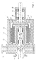
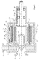
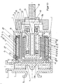
- a first known pump in conventional design is in FIG. 1 and is advertised, for example, in the brochure [1].
- a rotating pump impeller (4') is arranged, which receives the liquid to be conveyed via the suction nozzle (2 ') and ejects via the discharge nozzle (3') again under pressure.
- the radial bearing of the pump impeller (4 ') takes place by means of an impeller shaft (5') usually in plain bearings (9 ', 10'), the fixed parts in a bearing insert (11 ') are added.
- the lubrication and cooling of the sliding bearing (9 ', 10') takes place by the liquid to be pumped itself.
- This is equipped with permanent magnets (7 '), which in turn must be surrounded before the corrosive and possibly also abrasive attack of the pumped liquid with a cylindrical protective jacket (8') liquid-tight. It should be mentioned only marginally that it may be necessary to protect an approximately metallic, that is to say ferromagnetic, magnet rotor (6 ') from corrosion as well as the shaft (5').
- the part of the rotary coupling which receives and transmits the driving torque of the motor via the drive shaft (15 ') is commonly referred to as a magnet driver (13'). He is also equipped accordingly with permanent magnets (14 '), but rotate in air and therefore are not subject to any special attack.
- the radial and axial bearing of the magnetic drive takes place in commercial rolling bearings (16 ').
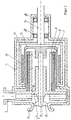
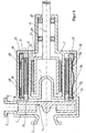
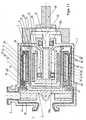
- FIG. 2 Another common design, especially for smaller pumps, shows FIG. 2 , Such a pump is advertised eg in [2].
- a bearing insert (11 ') can be inexpensively eliminated.
- the pump impeller (4 ') is combined with the magnet rotor (6'), the permanent magnet (7 ') and the protective jacket (8') to a part.
- This rotating impeller magnetic rotor unit (19 ') is slidably mounted here on a fixed axle (17').
- the axis (17 ') itself is fastened on one side via flow ribs (18') in the suction nozzle (2 '), supported on the other side in the specially shaped containment shell (12').
- type A largely conventional construction
- the magnet driver (13 ') is arranged radially outwardly over the further inside magnetic rotor (6').
- This design has the advantage that the high moment of inertia of the outside magnet driver (13 ') counteracts the too rapid startup of the driving motor and thus the tearing of the magnetic coupling can be prevented more favorable.
- this design facilitates in particular a generously axially spaced radial bearing of the pump impeller (4 '), which is always desirable due to the high hydraulic forces within the pump.
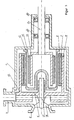
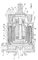
- magnetic coupling pumps with a magnet rotor (6 ') located radially on the outside, which is in contact with the liquid, and an internal magnetic driver (13') are less frequently used.
- This embodiment is referred to as type B.
- Such pumps of type B for example, in the DE 01453760 or EP 0171514 or EP 0171515 , are described and in FIG. 3 are shown, must be carefully designed so that the magnetic coupling does not break during rapid startup, which threatens here due to the outside magnetic rotor (6 '). Furthermore, the radially inner magnet driver (13 ') obstructs an axially pulled-out inner slide bearing of the impeller magnetic rotor unit (19'), if not the containment shell (12 '), with its actual opening in the type B drive side must be facing the pump, adversely wound right is executed.
- An executed pump type B is advertised in [3] and served as a template for the FIG. 3 , That here in contrast to the construction entspr.
- the present invention seeks to improve the radial bearing in the magnetic coupling of a generic centrifugal pump.
- a centrifugal pump with the features of claims 1 or 3 is proposed.
- the fixed part of the slide bearing is arranged on the inside wall surface of the pump housing as a whole or is formed independently by the housing wall or sections of the housing wall of the pump housing, high radial bearing forces can be transmitted over a large axial length and a smooth synchronization of the impeller magnet rotor Unit can be achieved.
- these are preferably located approximately at the same radial level in order to further improve the running characteristics and the dry running capability of the bearing.
- radial bearing forces can also be absorbed on the pump impeller, e.g. to achieve an improvement of runflat and / or starting properties. However, best synchronization conditions are achieved if the pump impeller can be rotated radially without contact or force.
- the sliding bearing of the impeller magnetic rotor unit is carried out in its rotating part as a continuous sleeve, optionally in the form of a molding compound, thereby best possible material pairings and protection of the permanent magnets of the magnet rotor can be improved or simplified.
- the rotating part of the sliding bearing of the impeller magnetic rotor unit has recesses or elevations on its outer circumference, thereby the sliding properties improving liquid movements can be generated.
- outside wall of the pump housing is provided in the region of the fixed part of the sliding bearing of the impeller magnetic rotor unit with cooling fins or a cooling jacket, overheating-related bearing damage can be avoided.
- the pump housing wall has a multilayer structure and the innermost material layer consists of a corrosion- or abrasion-resistant material, the longevity is improved even with difficult pumped media.
- centrifugal pump is independent of claim 1 of independent inventive importance.
- the magnet driver has at least one arranged in the region of the interior of the impeller magnetic rotor unit bearing, thereby the pump length can be significantly reduced despite independent storage of the magnetic driver within the pump.
- the magnetic drive bearing bearings are preferably used.
- the rolling bearing of the magnetic driver remains unaffected by the pumped liquid.
- the magnet driver preferably has an open towards the drive side cup shape to receive the at least one bearing of the magnet rotor within the pump housing.
- a particularly advantageous mounting of the magnetic driver is achieved by a hollow hollow cantilever, through which the drive shaft of the magnet driver is guided, and which preferably carries on at least one inner or outer surface at least one of its end portions a bearing for the magnetic driver. Tapering in these end areas facilitate the placement of such bearings in a small space. When the taper is made from the root of the cantilever, high bearing forces can be absorbed in a lightweight construction.
- the at least partial storage of the magnetic driver within the space defined by the impeller magnetic rotor unit and the embodiments of such storage are of independent inventive significance.
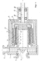
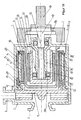
- the embodiments have in common that they have a suction nozzle 2 and a discharge nozzle 3 exhibiting pump housing 1, wherein a pump impeller 4 is mounted coaxially with the suction nozzle and is fluidly connected in the radial direction with the discharge nozzle 3.
- the pump impeller 4 has on the drive side a magnetic rotor 6, with which it forms an open to the drive side impeller magnetic rotor unit. This has on its outer circumference the rotating part 9 of a slide bearing, while the fixed part 10 of this sliding bearing is arranged on the inner wall 20 of the pump housing 1.
- On the radially inner side of the magnet rotor carries 6 permanent magnets 7.
- a continuous hollow Kragzapfen 39 from the drive-side housing end wall to the pump side down and has a tapered design 39a, 39b, wherein at its drive end portion which penetrates the drive shaft 15 of the pump is roller-mounted, while a second roller bearing in the opposite end on his Outside the drive shaft 15 indirectly, namely superimposed on the magnet driver 13.
- the latter has for this purpose on the drive side open cup shape.
- the fixed part 10 of the plain bearing can readily be brought directly to the stable inner housing wall 20 of the pump housing 1 ( FIG. 5 , upper half) and no longer has to be disadvantageous the basically thin wall of the can 12, as described in [4]. It is even possible, with a suitable choice of the material and with appropriate shaping, that parts of the housing wall 20 of the pump housing 1 itself can become the stationary part of the sliding bearing 10 ( FIG. 5 , lower half), possibly only by a multi-layered design.
- An arrangement according to claim 1 not only offers significant technological advantages, but also leads to an extremely simple construction of the entire pump.
- the slide bearing 9, 10 is arranged exactly here, which can be operated as long as desired with the residual liquid with sufficient cooling.
- very small residual amounts which tend to occur at high delivery heights of the pump and low static counter-pressure, it can not be ruled out that these can escape axially in order to move to even higher radial levels in the impeller. This can be prevented via a lock in the form of a circulating ring 21, in FIG. 6 is shown.
- the invention can also be exploited to significantly shorten the axial extent of the pump.
- This is usually an electric motor.
- the electric motor is flanged directly to the pump, which is known as "block construction".
- Advantage of this construction is in addition to the effect of axial shortening the savings of the two bearings 16.
- the disadvantage of this design is that the magnet driver 13 is no longer part of the pump and thus complete assembly of the pump can only be done if the driving motor present is.
- its size is initially at least in industrial pumps an unknown size and will be determined only on the basis of customer information.
- the time of final assembly of the pump is necessarily relocated behind this time and is also still an individual assembly with the known economic disadvantages.
- a, preferably detachable, split pot 12 introduced, as it always finds use in industrial pumps.
- these splitters are made very thin-walled on the circumference in order to realize the smallest possible radial gap between the magnet rotor 6 and magnet driver 13 can.
- the containment shell 12 can be designed with a smooth end wall and must point with its larger opening in the direction of the drive side.
- the split pot 12 itself should not be used to support a rolling bearing because of its thinness, but now offers according FIG. 7 In this way, the axial Baumass the pump can be shortened to that of the conventional block design, but here the magnet driver 13 remains part of the pump, resulting in a complete series assembly and stockpiling of the pump allowed.
- the shaft end 25 in such an axially shortened construction can advantageously according to FIG. 8 be carried out so that either via a conventional pump clutch (shown only the pin portion 27 of the pump clutch) the direct connection of a motor is possible (which could be flanged via an intermediate ring also directly to the pump) or a shaft journal 28 again with the conventional pump free shaft end leads (eg to comply with specified standard dimensions).
- a shaft end 25 should provide the opportunity to attach an additional flywheel 26 to compensate for the mentioned disadvantage of the type B chosen here when starting the pump can. All this would be part of the final assembly of the pump unit (which would also be carried out by the user of the pump itself) and would still allow a large-scale series assembly and cheap stockpiling of the pump at the manufacturer as described above.
- the rotating part 9 of the plain bearing need not necessarily consist of two defined bearing sleeves a and b or from the magnet rotor 6 itself, but can FIG. 9 also as an axially continuous sleeve 29 (FIG. FIG. 9 , upper half) or molding compound 30 ( FIG. 9 , lower half).
- the supply of external lubricating fluid is loud FIG. 13 and / or a sensory monitoring (eg temperature, vibration, structure-borne noise) of the sliding bearing 9, 10 loud FIG. 14 proposed.
- a sensory monitoring eg temperature, vibration, structure-borne noise
- FIG. 15 makes this construction also for the present invention. Since in particular the mentioned plastic materials (eg PTFE or PE) can be used very well as a sliding bearing material in mixed friction area, a construction is proposed, as they FIG. 15 in the lower half shows. If, on the other hand, the material of the innermost material layer 35 is not suitable for plain bearings, the construction in the upper half of FIG FIG. 15 recourse.
- plastic materials eg PTFE or PE
Landscapes
- Engineering & Computer Science (AREA)
- Mechanical Engineering (AREA)
- General Engineering & Computer Science (AREA)
- Physics & Mathematics (AREA)
- Electromagnetism (AREA)
- Structures Of Non-Positive Displacement Pumps (AREA)
- Sliding-Contact Bearings (AREA)
- Rolling Contact Bearings (AREA)
- Magnetic Bearings And Hydrostatic Bearings (AREA)
Claims (21)
- Pompe centrifuge,- comportant, à l'intérieur de la pompe en forme de carter (1), une enceinte statique et fermée pour le liquide à mettre en circulation,- comportant un accouplement rotatif (6, 7 ; 13, 14) coaxial à aimants permanents, destiné à transmettre un couple d'entraînement vers l'intérieur du carter de la pompe,- comportant une roue mobile (4) qui, conjointement avec un rotor magnétique (6), portant des aimants permanents (7), forme une unité en forme de pot (unité 19 à roue mobile et rotor magnétique), ouverte vers le côté entraînement et montée dans un palier lisse,- et dans laquelle les lignes d'action magnétiques de la partie motrice de l'accouplement rotatif (organe d'entraînement magnétique 13 et aimants permanents 14) sont dirigés radialement vers l'extérieur et les lignes d'action magnétique de la partie de l'accouplement rotatif (rotor magnétique 6 et aimants permanents 7), reliée à la roue mobile (4), sont dirigés radialement vers l'intérieur,caractérisée en ce que pour le montage radial de l'unité (19) à roue mobile et rotor magnétique,- la partie rotative (9 ; 9a, 9b) d'un palier lisse est montée dans son ensemble le long de la périphérie extérieure (38) du rotor magnétique (6) et est reliée de manière solidaire à celui-ci ou est formée elle-même par la périphérie extérieure ou des portions de la périphérie extérieure (38) du rotor magnétique (6).
- Pompe centrifuge selon la revendication 1, caractérisée en ce que la partie fixe (10 ; 10a, 10b) du palier lisse est agencée sur la paroi (20) intérieure du carter (1) de la pompe ou est formée elle-même par la paroi ou des portions de la paroi (20) du carter (1) de la pompe.
- Pompe centrifuge selon la revendication 1 ou 2, dans laquelle sont prévus plusieurs parties de palier lisse (9a, 10a ; 9b, 10b), situées à distance axiale les unes des autres et situées sensiblement sur le même niveau radial.
- Pompe centrifuge selon l'une quelconque des revendications 1 à 3, caractérisée en ce que la roue mobile (4) de la pompe est montée rotative radialement sans contact ou sans rotation forcée.
- Pompe centrifuge selon l'une quelconque des revendications 1 à 4, caractérisée en ce qu'entre la roue mobile (4) de la pompe et le palier lisse (9, 10) est montée une bague (21) rotative ou une bride, de telle sorte que la dimension intérieure de celle-ci est inférieure au diamètre de contact du palier lisse (9, 10) et, de ce fait, il se forme une chambre de retenue de liquide (22) dans la zone du palier lisse (9, 10) tant pendant la rotation que pendant l'immobilisation de la roue mobile (4) de la pompe.
- Pompe centrifuge selon l'une quelconque des revendications 1 à 5, caractérisée en ce que la partie rotative (9 ; 9a, 9b) du palier lisse est réalisée sous la forme d'un manchon (29) à passage axial ou sous la forme d'une masse profilée (30), moulée ou pressée, à passage axial.
- Pompe centrifuge selon la revendication 6, caractérisée en ce que le manchon (29) ou la masse profilée (30) sont ou seront posées, formées ou étanchées par des moyens d'étanchéité (36), de telle sorte qu'ils font partie d'une enveloppe de protection (8) pour les aimants permanents (7) et/ou le rotor magnétique (6).
- Pompe centrifuge selon l'une quelconque des revendications 1 à 7, caractérisée en ce que la partie rotative (9 ; 9a, 9b) du palier lisse comporte sur sa périphérie extérieure une pluralité d'évidements (31) ou bosses locaux, qui favorisent le développement de tourbillons hydrauliques stabilisants dans le palier lisse.
- Pompe centrifuge selon l'une quelconque des revendications 1 à 8, caractérisée en ce que la paroi extérieure du carter (1) de la pompe comporte des nervures de refroidissement (32) dans la zone de la partie fixe (10) du palier lisse.
- Pompe centrifuge selon l'une quelconque des revendications 1 à 9, caractérisée en ce que la partie fixe (10) du palier lisse peut être alimentée en lubrifiant externe par l'intermédiaire d'un ou de plusieurs accès (33) dans la paroi du carter (1) de la pompe.
- Pompe centrifuge selon l'une quelconque des revendications 1 à 10, caractérisée en ce que la partie fixe (10) du palier lisse peut être surveillée par capteurs par l'intermédiaire d'un ou de plusieurs accès (34) dans la paroi du carter (1) de la pompe.
- Pompe centrifuge selon l'une quelconque des revendications 1 à 11, caractérisée en ce que la paroi du carter (1) de la pompe est formée par plusieurs couches de matière et la couche intérieure (35) est réalisée dans un matériau résistant à la corrosion et/ou à l'abrasion.
- Pompe centrifuge selon l'une quelconque des revendications 1 à 12, dans laquelle une cloison est montée entre le rotor magnétique (6) et l'organe d'entraînement magnétique (13), laquelle est orientée avec son ouverture vers le côté entraînement de la pompe et fait la séparation entre le liquide à l'intérieur de la pompe et l'organe d'entraînement magnétique (13), caractérisée- en ce que l'organe d'entraînement magnétique (13) est monté dans au moins un palier relié à la pompe, tel qu'un palier à roulements (16),- en ce qu'au moins un palier du côté de la roue mobile, tel qu'un palier à roulements (16a), se situe dans la zone intérieure (24) du carter de la pompe, et- le montage de l'organe d'entraînement magnétique (13) est réalisé sans contact avec la cloison.
- Pompe centrifuge selon la revendication 13, caractérisée en ce que ledit au moins un palier du côté de la roue mobile se situe dans la zone intérieure d'un organe d'entraînement magnétique (13) creux à l'intérieur.
- Pompe centrifuge selon la revendication 13 ou 14, caractérisée en ce que la bague intérieure est immobilisée par le palier du côté roue mobile et la bague extérieure associée tourne avec l'organe d'entraînement magnétique (13) monté dans le palier.
- Pompe centrifuge selon la revendication 15, caractérisée en ce qu'il est prévu un palier du côté roue mobile, tel qu'un palier à roulements (16b), dont la bague intérieure tourne avec l'arbre d'entraînement (15) monté dans le palier et la bague extérieure associée est immobilisée.
- Pompe centrifuge selon l'une quelconque des revendications 13 à 16, caractérisée en ce qu'il est prévu un tourillon (39) en porte-à-faux, creux de part en part, lequel s'engage dans le carter (1) de la pompe depuis le côté entraînement, est destiné à recevoir l'arbre d'entraînement (15) et est relié ou peut être relié au carter de la pompe.
- Pompe centrifuge selon la revendication 17, caractérisée en ce que le tourillon creux (39) en porte-à-faux comporte un rétrécissement (39a ; 39b) dans au moins l'une de ses zones d'extrémité.
- Pompe centrifuge selon l'une quelconque des revendications 13 à 18, caractérisée en ce que la zone de l'extrémité (25) de l'arbre d'entraînement (15), du côté entraînement, est réalisée de telle sorte qu'elle comporte une masse d'inertie (26) ou peut être munie de celle-ci.
- Pompe centrifuge selon l'une quelconque des revendications 13 à 19, caractérisée en ce que la zone de l'extrémité (25) de l'arbre d'entraînement (15), du côté entraînement, est réalisée de telle sorte qu'elle peut être assemblée de manière amovible au choix à une masse d'inertie (26), une partie de tourillon (27) d'un accouplement de la pompe et/ou un tourillon d'arbre (28).
- Pompe centrifuge selon l'une quelconque des revendications 13 à 20, caractérisée en ce que l'organe d'entraînement magnétique (13) a une forme de pot ouvert vers le côté entraînement.
Priority Applications (1)
| Application Number | Priority Date | Filing Date | Title |
|---|---|---|---|
| EP08003862A EP1965081B1 (fr) | 2006-03-31 | 2007-03-29 | Pompe centrifuge dotée d'un embrayage magnétique coaxial |
Applications Claiming Priority (2)
| Application Number | Priority Date | Filing Date | Title |
|---|---|---|---|
| DE202006005189U DE202006005189U1 (de) | 2006-03-31 | 2006-03-31 | Kreiselpumpe mit koaxialer Magnetkupplung |
| PCT/EP2007/002814 WO2007112938A2 (fr) | 2006-03-31 | 2007-03-29 | Pompe centrifuge à accouplement magnétique coaxial |
Related Child Applications (2)
| Application Number | Title | Priority Date | Filing Date |
|---|---|---|---|
| EP08003862A Division EP1965081B1 (fr) | 2006-03-31 | 2007-03-29 | Pompe centrifuge dotée d'un embrayage magnétique coaxial |
| EP08003862.3 Division-Into | 2008-03-01 |
Publications (2)
| Publication Number | Publication Date |
|---|---|
| EP2002126A2 EP2002126A2 (fr) | 2008-12-17 |
| EP2002126B1 true EP2002126B1 (fr) | 2010-06-23 |
Family
ID=38375284
Family Applications (2)
| Application Number | Title | Priority Date | Filing Date |
|---|---|---|---|
| EP08003862A Not-in-force EP1965081B1 (fr) | 2006-03-31 | 2007-03-29 | Pompe centrifuge dotée d'un embrayage magnétique coaxial |
| EP07723756A Not-in-force EP2002126B1 (fr) | 2006-03-31 | 2007-03-29 | Pompe centrifuge à accouplement magnétique coaxial |
Family Applications Before (1)
| Application Number | Title | Priority Date | Filing Date |
|---|---|---|---|
| EP08003862A Not-in-force EP1965081B1 (fr) | 2006-03-31 | 2007-03-29 | Pompe centrifuge dotée d'un embrayage magnétique coaxial |
Country Status (9)
| Country | Link |
|---|---|
| US (1) | US8162630B2 (fr) |
| EP (2) | EP1965081B1 (fr) |
| JP (1) | JP5461172B2 (fr) |
| KR (1) | KR101410628B1 (fr) |
| CN (1) | CN101415950B (fr) |
| AT (2) | ATE472060T1 (fr) |
| DE (3) | DE202006005189U1 (fr) |
| ES (1) | ES2335946T3 (fr) |
| WO (1) | WO2007112938A2 (fr) |
Cited By (1)
| Publication number | Priority date | Publication date | Assignee | Title |
|---|---|---|---|---|
| DE102009060549A1 (de) * | 2009-12-23 | 2011-06-30 | Wilo Se, 44263 | EC-Motorkreiselpumpe |
Families Citing this family (49)
| Publication number | Priority date | Publication date | Assignee | Title |
|---|---|---|---|---|
| DE102007054233B4 (de) | 2007-11-12 | 2010-06-10 | Ika-Werke Gmbh & Co. Kg | Vorrichtung zum Dispergieren oder Homogenisieren |
| ES2776709T3 (es) | 2007-11-21 | 2020-07-31 | Smith & Nephew | Apósito para heridas |
| DE102008008290A1 (de) | 2008-02-07 | 2009-08-20 | H. Wernert & Co. Ohg | Laufradanordnung für eine Pumpe sowie Verfahren zum Herstellen einer solchen Laufradanordnung |
| JP4681625B2 (ja) | 2008-02-22 | 2011-05-11 | 三菱重工業株式会社 | 血液ポンプおよびポンプユニット |
| EP2180583B1 (fr) * | 2008-10-24 | 2012-08-08 | Biazzi Sa | Appareillage à cuve d'agitation |
| KR100935707B1 (ko) * | 2009-04-30 | 2010-01-07 | 케이이티주식회사 | 마그네틱 구동 시일리스 펌프 |
| KR100990096B1 (ko) | 2009-06-04 | 2010-10-29 | 강선희 | 마그네트모듈이 적용된 물품 이송시스템 |
| MX341039B (es) * | 2010-04-19 | 2016-08-04 | Kolektor Magnet Tech Gmbh | Bomba de refrigerante para automovil electrica. |
| JP4875783B1 (ja) * | 2011-09-15 | 2012-02-15 | 三菱重工業株式会社 | 磁気カップリングポンプ及びこれを備えているポンプユニット |
| TW201317459A (zh) * | 2011-10-26 | 2013-05-01 | 協磁股份有限公司 | 永磁罐裝泵結構改良 |
| CN102352848A (zh) * | 2011-10-31 | 2012-02-15 | 神华集团有限责任公司 | 磁力泵 |
| TW201320547A (zh) * | 2011-11-03 | 2013-05-16 | Assoma Inc | 磁驅動泵浦之結構改良 |
| PL2604863T3 (pl) * | 2011-12-13 | 2017-12-29 | Eagleburgmann Germany Gmbh & Co. Kg | Sprężarka rotacyjna |
| US8651240B1 (en) | 2012-12-24 | 2014-02-18 | United Technologies Corporation | Pressurized reserve lubrication system for a gas turbine engine |
| US8905729B2 (en) | 2011-12-30 | 2014-12-09 | Peopleflo Manufacturing, Inc. | Rotodynamic pump with electro-magnet coupling inside the impeller |
| US8905728B2 (en) | 2011-12-30 | 2014-12-09 | Peopleflo Manufacturing, Inc. | Rotodynamic pump with permanent magnet coupling inside the impeller |
| CN102931810A (zh) * | 2012-11-27 | 2013-02-13 | 镇江市江南矿山机电设备有限公司 | 轴间永磁耦合机构 |
| CN103023241A (zh) * | 2012-11-27 | 2013-04-03 | 镇江市江南矿山机电设备有限公司 | 轴间永磁耦合机构 |
| CN102931809A (zh) * | 2012-11-27 | 2013-02-13 | 镇江市江南矿山机电设备有限公司 | 轴间永磁耦合机构 |
| CN103401396B (zh) * | 2013-06-14 | 2016-07-06 | 宝鸡泰华磁机电技术研究所有限公司 | 内辐射环式永磁联轴器 |
| KR101828544B1 (ko) * | 2013-12-13 | 2018-03-29 | 한화파워시스템 주식회사 | 압축기 어셈블리 |
| US9771938B2 (en) | 2014-03-11 | 2017-09-26 | Peopleflo Manufacturing, Inc. | Rotary device having a radial magnetic coupling |
| HK1255306A1 (zh) * | 2015-08-05 | 2019-08-16 | W‧斯皮塞 | 磁力驱动的无密封泵 |
| DE102016200013B4 (de) | 2016-01-04 | 2022-11-03 | Röchling Automotive SE & Co. KG | Pumpe |
| CN107327570B (zh) * | 2016-04-28 | 2018-10-19 | 哈尔滨歌瑞得莱机器人制造有限公司 | 同步双磁环驱动密封装置 |
| CN109416058B (zh) | 2016-07-04 | 2021-05-07 | 阿莫泰克有限公司 | 水泵 |
| WO2018008896A1 (fr) * | 2016-07-04 | 2018-01-11 | 주식회사 아모텍 | Pompe à eau |
| DE202016105312U1 (de) * | 2016-09-23 | 2018-01-09 | Speck Pumpen Verkaufsgesellschaft Gmbh | Förderpumpe |
| EP3523539B1 (fr) * | 2016-11-01 | 2020-08-12 | PSG Worldwide, Inc. | Pompe centrifuge sans joint à entraînement magnétique |
| NO344365B1 (en) * | 2017-12-21 | 2019-11-18 | Fsubsea As | Magnetic coupling assembly |
| DE102017220437B8 (de) * | 2017-11-16 | 2019-06-19 | Eagleburgmann Germany Gmbh & Co. Kg | Pumpenanordnung, insbesondere zur Versorgung einer Gleitringdichtungsanordnung |
| DE102017127736A1 (de) * | 2017-11-23 | 2019-05-23 | Manfred Sade | Magnetpumpe mit Gleitringdichtung |
| US10047717B1 (en) * | 2018-02-05 | 2018-08-14 | Energystics, Ltd. | Linear faraday induction generator for the generation of electrical power from ocean wave kinetic energy and arrangements thereof |
| DE102018102740A1 (de) * | 2018-02-07 | 2019-08-08 | Lsp Innovative Automotive Systems Gmbh | Außenstator für eine Drehfeldmaschine (E-Motor) mit einem Innenrotor, mit Statorzahngruppen, welche jeweils zwei zueinander benachbarte Statorzähne aufweisen |
| CN108462366A (zh) * | 2018-03-30 | 2018-08-28 | 湖南铁路科技职业技术学院 | 适用于铁路货车的圆柱与圆锥混合型同轴式磁力密封装置 |
| US10947986B2 (en) | 2018-07-11 | 2021-03-16 | Ch Biomedical (Usa) Inc. | Compact centrifugal pump with magnetically suspended impeller |
| CN109067138A (zh) * | 2018-08-27 | 2018-12-21 | 广西科技大学 | 一种新型混合式永磁传动装置 |
| DE102018129613A1 (de) * | 2018-11-23 | 2020-05-28 | Ebm-Papst St. Georgen Gmbh & Co. Kg | Radiallüfter mit integrierter Kühlfunktion |
| GB2581339A (en) * | 2019-02-08 | 2020-08-19 | Hmd Seal/Less Pumps Ltd | Containment shell for a magnetic pump |
| KR102817631B1 (ko) * | 2019-04-18 | 2025-06-10 | 한화파워시스템 주식회사 | 회전 기기 |
| DE102019122042A1 (de) * | 2019-08-16 | 2021-02-18 | HELLA GmbH & Co. KGaA | Pumpvorrichtung |
| EP3795836B1 (fr) * | 2019-09-18 | 2024-11-27 | Levitronix GmbH | Pompe centrifuge |
| DE102020202781A1 (de) * | 2020-03-04 | 2021-09-09 | Siemens Aktiengesellschaft | 8Elektromotor mit Spaltrohr |
| DE202020101750U1 (de) * | 2020-03-31 | 2020-04-15 | Speck Pumpen Verkaufsgesellschaft Gmbh | Gegenstromschwimmanlage |
| CN114263637B (zh) * | 2021-12-30 | 2024-01-02 | 浙江启尔机电技术有限公司 | 一种磁力联轴器温度控制系统及采用其的磁力泵 |
| EP4539307A4 (fr) * | 2022-06-08 | 2025-08-27 | Panasonic Ip Man Co Ltd | Moteur à engrenage magnétique et engrenage magnétique |
| CN117703777B (zh) * | 2023-12-12 | 2024-10-18 | 安徽星球盛唐泵业有限公司 | 耐腐蚀耐高温磁力泵 |
| CN119737318B (zh) * | 2024-12-19 | 2025-10-28 | 西安交通大学 | 一种轴流式高温液态金属磁力泵 |
| CN120312614A (zh) * | 2025-06-16 | 2025-07-15 | 凯利达科技股份有限公司 | 一种双支撑轴磁力泵 |
Family Cites Families (13)
| Publication number | Priority date | Publication date | Assignee | Title |
|---|---|---|---|---|
| DE1453760A1 (de) | 1962-01-08 | 1969-01-09 | Fuss Und Stahl Veredlung Gmbh | Pumpe mit einem schnell rotierend angetriebenen Laufrad,insbesondere Kreiselpumpe |
| FR2311201A1 (fr) * | 1975-05-12 | 1976-12-10 | Siebec Filtres | Perfectionnement apporte aux pompes a entrainement magnetique |
| JPS5280101U (fr) * | 1975-12-11 | 1977-06-15 | ||
| EP0171515B1 (fr) * | 1984-07-16 | 1987-09-02 | CP Pumpen AG | Pompe centrifuge avec chapeau tubulaire d'isolation de l'entrefer |
| ATE32931T1 (de) | 1984-07-16 | 1988-03-15 | Cp Pumpen Ag | Kreiselpumpe mit einem spaltrohrtopf. |
| JP2636097B2 (ja) * | 1991-08-08 | 1997-07-30 | 動力炉・核燃料開発事業団 | 浸漬型電動ポンプにおけるスラスト軸受の摩耗量の監視装置 |
| GB2263312A (en) * | 1992-01-17 | 1993-07-21 | Stork Pompen | Vertical pump with magnetic coupling. |
| US5253986A (en) | 1992-05-12 | 1993-10-19 | Milton Roy Company | Impeller-type pump system |
| FR2715442B1 (fr) * | 1994-01-26 | 1996-03-01 | Lorraine Carbone | Pompe centrifuge à entraînement magnétique. |
| JPH09268994A (ja) * | 1996-03-30 | 1997-10-14 | Yoshio Yano | 液中軸承のない、マグネットを動力源とするポンプ |
| GB9717866D0 (en) * | 1997-08-23 | 1997-10-29 | Concentric Pumps Ltd | Improvements to rotary pumps |
| DE29822717U1 (de) * | 1998-12-21 | 1999-03-18 | Feodor Burgmann Dichtungswerke GmbH & Co, 82515 Wolfratshausen | Kreiselpumpe, insbesondere zum Pumpen eines Kühlmittels in einem Kühlmittelkreislauf |
| JP2001119913A (ja) * | 1999-10-21 | 2001-04-27 | Canon Precision Inc | 自冷動圧流体軸受ブラシレスモータ |
-
2006
- 2006-03-31 DE DE202006005189U patent/DE202006005189U1/de not_active Expired - Lifetime
-
2007
- 2007-03-29 KR KR1020087026741A patent/KR101410628B1/ko not_active Expired - Fee Related
- 2007-03-29 JP JP2009501958A patent/JP5461172B2/ja not_active Expired - Fee Related
- 2007-03-29 AT AT07723756T patent/ATE472060T1/de active
- 2007-03-29 DE DE502007002031T patent/DE502007002031D1/de active Active
- 2007-03-29 CN CN2007800118957A patent/CN101415950B/zh not_active Expired - Fee Related
- 2007-03-29 US US12/295,350 patent/US8162630B2/en not_active Expired - Fee Related
- 2007-03-29 AT AT08003862T patent/ATE449263T1/de active
- 2007-03-29 EP EP08003862A patent/EP1965081B1/fr not_active Not-in-force
- 2007-03-29 EP EP07723756A patent/EP2002126B1/fr not_active Not-in-force
- 2007-03-29 ES ES08003862T patent/ES2335946T3/es active Active
- 2007-03-29 WO PCT/EP2007/002814 patent/WO2007112938A2/fr not_active Ceased
- 2007-03-29 DE DE502007004191T patent/DE502007004191D1/de active Active
Cited By (1)
| Publication number | Priority date | Publication date | Assignee | Title |
|---|---|---|---|---|
| DE102009060549A1 (de) * | 2009-12-23 | 2011-06-30 | Wilo Se, 44263 | EC-Motorkreiselpumpe |
Also Published As
| Publication number | Publication date |
|---|---|
| EP1965081A1 (fr) | 2008-09-03 |
| CN101415950B (zh) | 2013-02-06 |
| CN101415950A (zh) | 2009-04-22 |
| DE502007004191D1 (de) | 2010-08-05 |
| US8162630B2 (en) | 2012-04-24 |
| WO2007112938A3 (fr) | 2008-04-10 |
| JP5461172B2 (ja) | 2014-04-02 |
| US20100028176A1 (en) | 2010-02-04 |
| EP2002126A2 (fr) | 2008-12-17 |
| KR20080108150A (ko) | 2008-12-11 |
| JP2009531589A (ja) | 2009-09-03 |
| EP1965081B1 (fr) | 2009-11-18 |
| DE502007002031D1 (de) | 2009-12-31 |
| KR101410628B1 (ko) | 2014-06-20 |
| WO2007112938A2 (fr) | 2007-10-11 |
| ATE472060T1 (de) | 2010-07-15 |
| ES2335946T3 (es) | 2010-04-06 |
| ATE449263T1 (de) | 2009-12-15 |
| DE202006005189U1 (de) | 2007-08-16 |
Similar Documents
| Publication | Publication Date | Title |
|---|---|---|
| EP2002126B1 (fr) | Pompe centrifuge à accouplement magnétique coaxial | |
| EP1801420A2 (fr) | Pompe centrifuge à accouplement magnétique | |
| DE102010014800B4 (de) | Gekapselte Dauermagnet-Pumpe | |
| EP3127221B1 (fr) | Dispositif pour la lubrification du palier à roulement d'un moteur électrique | |
| DE3639719C3 (de) | Spaltrohrmagnetpumpe | |
| DE202008002617U1 (de) | Anordnung zur Förderung von Fluiden | |
| EP3433496A1 (fr) | Pompe à entraînement magnétique | |
| DE102011109930A1 (de) | Wälzlager und Vakuumpumpe mit Wälzlager | |
| EP2576996B1 (fr) | Turbocompresseur à gaz d'échappement doté de paliers lisses pour diminuer les tourbillons de fluide | |
| EP2557316A2 (fr) | Pompe à vide | |
| DE1140595B (de) | Fuellungsgeregelte Stroemungskupplung, vorzugsweise fuer den Antrieb eines Bremsluft-kompressors in einem Schienenfahrzeug | |
| EP1979621B1 (fr) | Pompe centrifuge à entraînement magnétique pour des milieux corrosifs | |
| EP2322803B1 (fr) | Pompe dotée d un embrayage magnétique | |
| DE102008038012A1 (de) | Ausgleichswelle sowie Rotationssymmetrie-Ergänzungselement für eine derartige Ausgleichswelle | |
| EP2864640B1 (fr) | Pompe centrifuge de moteur pourvue d'une garniture étanche à anneau glissant | |
| EP1727987B1 (fr) | Pompe | |
| DE3941444C2 (de) | Permanentmagnetantrieb für eine Pumpe, ein Rührwerk oder eine Armatur | |
| WO2014170113A1 (fr) | Retardateur comprenant une pompe à vide | |
| EP3536956B1 (fr) | Sacs de support | |
| DE102014212600A1 (de) | Integrierte Schmierpumpe | |
| EP2667034B1 (fr) | Pompe à plusieurs étages | |
| EP2927500B1 (fr) | Procédé et système d'alimentation d'une disposition de palier | |
| EP3628873B1 (fr) | Logement de rotor | |
| EP2045477B1 (fr) | Agencement de stockage destiné au stockage rotatif d'une partie de machine | |
| DE202004013081U1 (de) | Spalttopfpumpe |
Legal Events
| Date | Code | Title | Description |
|---|---|---|---|
| PUAI | Public reference made under article 153(3) epc to a published international application that has entered the european phase |
Free format text: ORIGINAL CODE: 0009012 |
|
| 17P | Request for examination filed |
Effective date: 20080301 |
|
| AK | Designated contracting states |
Kind code of ref document: A2 Designated state(s): AT BE BG CH CY CZ DE DK EE ES FI FR GB GR HU IE IS IT LI LT LU LV MC MT NL PL PT RO SE SI SK TR |
|
| 17Q | First examination report despatched |
Effective date: 20090325 |
|
| GRAP | Despatch of communication of intention to grant a patent |
Free format text: ORIGINAL CODE: EPIDOSNIGR1 |
|
| GRAS | Grant fee paid |
Free format text: ORIGINAL CODE: EPIDOSNIGR3 |
|
| GRAA | (expected) grant |
Free format text: ORIGINAL CODE: 0009210 |
|
| AK | Designated contracting states |
Kind code of ref document: B1 Designated state(s): AT BE BG CH CY CZ DE DK EE ES FI FR GB GR HU IE IS IT LI LT LU LV MC MT NL PL PT RO SE SI SK TR |
|
| REG | Reference to a national code |
Ref country code: CH Ref legal event code: EP |
|
| REG | Reference to a national code |
Ref country code: IE Ref legal event code: FG4D Free format text: LANGUAGE OF EP DOCUMENT: GERMAN |
|
| REF | Corresponds to: |
Ref document number: 502007004191 Country of ref document: DE Date of ref document: 20100805 Kind code of ref document: P |
|
| REG | Reference to a national code |
Ref country code: CH Ref legal event code: NV Representative=s name: E. BLUM & CO. AG PATENT- UND MARKENANWAELTE VSP |
|
| REG | Reference to a national code |
Ref country code: NL Ref legal event code: T3 |
|
| PG25 | Lapsed in a contracting state [announced via postgrant information from national office to epo] |
Ref country code: SE Free format text: LAPSE BECAUSE OF FAILURE TO SUBMIT A TRANSLATION OF THE DESCRIPTION OR TO PAY THE FEE WITHIN THE PRESCRIBED TIME-LIMIT Effective date: 20100623 Ref country code: LT Free format text: LAPSE BECAUSE OF FAILURE TO SUBMIT A TRANSLATION OF THE DESCRIPTION OR TO PAY THE FEE WITHIN THE PRESCRIBED TIME-LIMIT Effective date: 20100623 |
|
| LTIE | Lt: invalidation of european patent or patent extension |
Effective date: 20100623 |
|
| PG25 | Lapsed in a contracting state [announced via postgrant information from national office to epo] |
Ref country code: SI Free format text: LAPSE BECAUSE OF FAILURE TO SUBMIT A TRANSLATION OF THE DESCRIPTION OR TO PAY THE FEE WITHIN THE PRESCRIBED TIME-LIMIT Effective date: 20100623 Ref country code: FI Free format text: LAPSE BECAUSE OF FAILURE TO SUBMIT A TRANSLATION OF THE DESCRIPTION OR TO PAY THE FEE WITHIN THE PRESCRIBED TIME-LIMIT Effective date: 20100623 Ref country code: LV Free format text: LAPSE BECAUSE OF FAILURE TO SUBMIT A TRANSLATION OF THE DESCRIPTION OR TO PAY THE FEE WITHIN THE PRESCRIBED TIME-LIMIT Effective date: 20100623 |
|
| PG25 | Lapsed in a contracting state [announced via postgrant information from national office to epo] |
Ref country code: PL Free format text: LAPSE BECAUSE OF FAILURE TO SUBMIT A TRANSLATION OF THE DESCRIPTION OR TO PAY THE FEE WITHIN THE PRESCRIBED TIME-LIMIT Effective date: 20100623 |
|
| PG25 | Lapsed in a contracting state [announced via postgrant information from national office to epo] |
Ref country code: EE Free format text: LAPSE BECAUSE OF FAILURE TO SUBMIT A TRANSLATION OF THE DESCRIPTION OR TO PAY THE FEE WITHIN THE PRESCRIBED TIME-LIMIT Effective date: 20100623 |
|
| REG | Reference to a national code |
Ref country code: IE Ref legal event code: FD4D |
|
| PG25 | Lapsed in a contracting state [announced via postgrant information from national office to epo] |
Ref country code: SK Free format text: LAPSE BECAUSE OF FAILURE TO SUBMIT A TRANSLATION OF THE DESCRIPTION OR TO PAY THE FEE WITHIN THE PRESCRIBED TIME-LIMIT Effective date: 20100623 Ref country code: CZ Free format text: LAPSE BECAUSE OF FAILURE TO SUBMIT A TRANSLATION OF THE DESCRIPTION OR TO PAY THE FEE WITHIN THE PRESCRIBED TIME-LIMIT Effective date: 20100623 Ref country code: RO Free format text: LAPSE BECAUSE OF FAILURE TO SUBMIT A TRANSLATION OF THE DESCRIPTION OR TO PAY THE FEE WITHIN THE PRESCRIBED TIME-LIMIT Effective date: 20100623 Ref country code: PT Free format text: LAPSE BECAUSE OF FAILURE TO SUBMIT A TRANSLATION OF THE DESCRIPTION OR TO PAY THE FEE WITHIN THE PRESCRIBED TIME-LIMIT Effective date: 20101025 Ref country code: IS Free format text: LAPSE BECAUSE OF FAILURE TO SUBMIT A TRANSLATION OF THE DESCRIPTION OR TO PAY THE FEE WITHIN THE PRESCRIBED TIME-LIMIT Effective date: 20101023 Ref country code: CY Free format text: LAPSE BECAUSE OF FAILURE TO SUBMIT A TRANSLATION OF THE DESCRIPTION OR TO PAY THE FEE WITHIN THE PRESCRIBED TIME-LIMIT Effective date: 20100623 |
|
| PG25 | Lapsed in a contracting state [announced via postgrant information from national office to epo] |
Ref country code: IT Free format text: LAPSE BECAUSE OF FAILURE TO SUBMIT A TRANSLATION OF THE DESCRIPTION OR TO PAY THE FEE WITHIN THE PRESCRIBED TIME-LIMIT Effective date: 20100623 |
|
| PG25 | Lapsed in a contracting state [announced via postgrant information from national office to epo] |
Ref country code: IE Free format text: LAPSE BECAUSE OF FAILURE TO SUBMIT A TRANSLATION OF THE DESCRIPTION OR TO PAY THE FEE WITHIN THE PRESCRIBED TIME-LIMIT Effective date: 20100623 Ref country code: DK Free format text: LAPSE BECAUSE OF FAILURE TO SUBMIT A TRANSLATION OF THE DESCRIPTION OR TO PAY THE FEE WITHIN THE PRESCRIBED TIME-LIMIT Effective date: 20100623 |
|
| PLBE | No opposition filed within time limit |
Free format text: ORIGINAL CODE: 0009261 |
|
| STAA | Information on the status of an ep patent application or granted ep patent |
Free format text: STATUS: NO OPPOSITION FILED WITHIN TIME LIMIT |
|
| PG25 | Lapsed in a contracting state [announced via postgrant information from national office to epo] |
Ref country code: GR Free format text: LAPSE BECAUSE OF FAILURE TO SUBMIT A TRANSLATION OF THE DESCRIPTION OR TO PAY THE FEE WITHIN THE PRESCRIBED TIME-LIMIT Effective date: 20100924 |
|
| 26N | No opposition filed |
Effective date: 20110324 |
|
| REG | Reference to a national code |
Ref country code: DE Ref legal event code: R097 Ref document number: 502007004191 Country of ref document: DE Effective date: 20110323 |
|
| BERE | Be: lapsed |
Owner name: H. WERNERT & CO. OHG Effective date: 20110331 |
|
| PG25 | Lapsed in a contracting state [announced via postgrant information from national office to epo] |
Ref country code: MC Free format text: LAPSE BECAUSE OF NON-PAYMENT OF DUE FEES Effective date: 20110331 |
|
| PG25 | Lapsed in a contracting state [announced via postgrant information from national office to epo] |
Ref country code: MT Free format text: LAPSE BECAUSE OF FAILURE TO SUBMIT A TRANSLATION OF THE DESCRIPTION OR TO PAY THE FEE WITHIN THE PRESCRIBED TIME-LIMIT Effective date: 20100623 Ref country code: BE Free format text: LAPSE BECAUSE OF NON-PAYMENT OF DUE FEES Effective date: 20110331 |
|
| PG25 | Lapsed in a contracting state [announced via postgrant information from national office to epo] |
Ref country code: DE Free format text: LAPSE BECAUSE OF NON-PAYMENT OF DUE FEES Effective date: 20111001 |
|
| REG | Reference to a national code |
Ref country code: AT Ref legal event code: MM01 Ref document number: 472060 Country of ref document: AT Kind code of ref document: T Effective date: 20120329 |
|
| PG25 | Lapsed in a contracting state [announced via postgrant information from national office to epo] |
Ref country code: LU Free format text: LAPSE BECAUSE OF NON-PAYMENT OF DUE FEES Effective date: 20110329 |
|
| PG25 | Lapsed in a contracting state [announced via postgrant information from national office to epo] |
Ref country code: AT Free format text: LAPSE BECAUSE OF NON-PAYMENT OF DUE FEES Effective date: 20120329 |
|
| PG25 | Lapsed in a contracting state [announced via postgrant information from national office to epo] |
Ref country code: TR Free format text: LAPSE BECAUSE OF FAILURE TO SUBMIT A TRANSLATION OF THE DESCRIPTION OR TO PAY THE FEE WITHIN THE PRESCRIBED TIME-LIMIT Effective date: 20100623 Ref country code: BG Free format text: LAPSE BECAUSE OF FAILURE TO SUBMIT A TRANSLATION OF THE DESCRIPTION OR TO PAY THE FEE WITHIN THE PRESCRIBED TIME-LIMIT Effective date: 20100923 |
|
| PG25 | Lapsed in a contracting state [announced via postgrant information from national office to epo] |
Ref country code: ES Free format text: LAPSE BECAUSE OF FAILURE TO SUBMIT A TRANSLATION OF THE DESCRIPTION OR TO PAY THE FEE WITHIN THE PRESCRIBED TIME-LIMIT Effective date: 20101004 Ref country code: HU Free format text: LAPSE BECAUSE OF FAILURE TO SUBMIT A TRANSLATION OF THE DESCRIPTION OR TO PAY THE FEE WITHIN THE PRESCRIBED TIME-LIMIT Effective date: 20100623 |
|
| REG | Reference to a national code |
Ref country code: FR Ref legal event code: PLFP Year of fee payment: 10 |
|
| REG | Reference to a national code |
Ref country code: FR Ref legal event code: PLFP Year of fee payment: 11 |
|
| PGFP | Annual fee paid to national office [announced via postgrant information from national office to epo] |
Ref country code: NL Payment date: 20170323 Year of fee payment: 11 Ref country code: DE Payment date: 20170327 Year of fee payment: 11 Ref country code: CH Payment date: 20170327 Year of fee payment: 11 Ref country code: FR Payment date: 20170323 Year of fee payment: 11 |
|
| PGFP | Annual fee paid to national office [announced via postgrant information from national office to epo] |
Ref country code: GB Payment date: 20170327 Year of fee payment: 11 |
|
| REG | Reference to a national code |
Ref country code: DE Ref legal event code: R119 Ref document number: 502007004191 Country of ref document: DE |
|
| REG | Reference to a national code |
Ref country code: CH Ref legal event code: PL |
|
| REG | Reference to a national code |
Ref country code: NL Ref legal event code: MM Effective date: 20180401 |
|
| GBPC | Gb: european patent ceased through non-payment of renewal fee |
Effective date: 20180329 |
|
| PG25 | Lapsed in a contracting state [announced via postgrant information from national office to epo] |
Ref country code: NL Free format text: LAPSE BECAUSE OF NON-PAYMENT OF DUE FEES Effective date: 20180401 |
|
| PG25 | Lapsed in a contracting state [announced via postgrant information from national office to epo] |
Ref country code: GB Free format text: LAPSE BECAUSE OF NON-PAYMENT OF DUE FEES Effective date: 20180329 Ref country code: LI Free format text: LAPSE BECAUSE OF NON-PAYMENT OF DUE FEES Effective date: 20180331 Ref country code: CH Free format text: LAPSE BECAUSE OF NON-PAYMENT OF DUE FEES Effective date: 20180331 |
|
| PG25 | Lapsed in a contracting state [announced via postgrant information from national office to epo] |
Ref country code: FR Free format text: LAPSE BECAUSE OF NON-PAYMENT OF DUE FEES Effective date: 20180331 |
|
| PG25 | Lapsed in a contracting state [announced via postgrant information from national office to epo] |
Ref country code: DE Free format text: LAPSE BECAUSE OF NON-PAYMENT OF DUE FEES Effective date: 20181002 |