EP2576996B1 - Turbocompresseur à gaz d'échappement doté de paliers lisses pour diminuer les tourbillons de fluide - Google Patents
Turbocompresseur à gaz d'échappement doté de paliers lisses pour diminuer les tourbillons de fluide Download PDFInfo
- Publication number
- EP2576996B1 EP2576996B1 EP11721317.3A EP11721317A EP2576996B1 EP 2576996 B1 EP2576996 B1 EP 2576996B1 EP 11721317 A EP11721317 A EP 11721317A EP 2576996 B1 EP2576996 B1 EP 2576996B1
- Authority
- EP
- European Patent Office
- Prior art keywords
- rotor shaft
- groove
- transverse
- inner segment
- gas turbocharger
- Prior art date
- Legal status (The legal status is an assumption and is not a legal conclusion. Google has not performed a legal analysis and makes no representation as to the accuracy of the status listed.)
- Not-in-force
Links
- 239000012530 fluid Substances 0.000 title claims description 85
- 230000003247 decreasing effect Effects 0.000 claims description 5
- 230000007423 decrease Effects 0.000 claims 1
- 230000000694 effects Effects 0.000 description 4
- 230000001419 dependent effect Effects 0.000 description 3
- 238000005086 pumping Methods 0.000 description 3
- 238000007667 floating Methods 0.000 description 2
- 230000010355 oscillation Effects 0.000 description 2
- 238000005452 bending Methods 0.000 description 1
- 230000015572 biosynthetic process Effects 0.000 description 1
- 238000010276 construction Methods 0.000 description 1
- 230000001066 destructive effect Effects 0.000 description 1
- 238000002955 isolation Methods 0.000 description 1
- 238000011017 operating method Methods 0.000 description 1
Images


Classifications
-
- F—MECHANICAL ENGINEERING; LIGHTING; HEATING; WEAPONS; BLASTING
- F01—MACHINES OR ENGINES IN GENERAL; ENGINE PLANTS IN GENERAL; STEAM ENGINES
- F01D—NON-POSITIVE DISPLACEMENT MACHINES OR ENGINES, e.g. STEAM TURBINES
- F01D25/00—Component parts, details, or accessories, not provided for in, or of interest apart from, other groups
- F01D25/16—Arrangement of bearings; Supporting or mounting bearings in casings
- F01D25/166—Sliding contact bearing
-
- F—MECHANICAL ENGINEERING; LIGHTING; HEATING; WEAPONS; BLASTING
- F01—MACHINES OR ENGINES IN GENERAL; ENGINE PLANTS IN GENERAL; STEAM ENGINES
- F01D—NON-POSITIVE DISPLACEMENT MACHINES OR ENGINES, e.g. STEAM TURBINES
- F01D25/00—Component parts, details, or accessories, not provided for in, or of interest apart from, other groups
- F01D25/18—Lubricating arrangements
-
- F—MECHANICAL ENGINEERING; LIGHTING; HEATING; WEAPONS; BLASTING
- F16—ENGINEERING ELEMENTS AND UNITS; GENERAL MEASURES FOR PRODUCING AND MAINTAINING EFFECTIVE FUNCTIONING OF MACHINES OR INSTALLATIONS; THERMAL INSULATION IN GENERAL
- F16C—SHAFTS; FLEXIBLE SHAFTS; ELEMENTS OR CRANKSHAFT MECHANISMS; ROTARY BODIES OTHER THAN GEARING ELEMENTS; BEARINGS
- F16C17/00—Sliding-contact bearings for exclusively rotary movement
- F16C17/02—Sliding-contact bearings for exclusively rotary movement for radial load only
- F16C17/026—Sliding-contact bearings for exclusively rotary movement for radial load only with helical grooves in the bearing surface to generate hydrodynamic pressure, e.g. herringbone grooves
-
- F—MECHANICAL ENGINEERING; LIGHTING; HEATING; WEAPONS; BLASTING
- F16—ENGINEERING ELEMENTS AND UNITS; GENERAL MEASURES FOR PRODUCING AND MAINTAINING EFFECTIVE FUNCTIONING OF MACHINES OR INSTALLATIONS; THERMAL INSULATION IN GENERAL
- F16C—SHAFTS; FLEXIBLE SHAFTS; ELEMENTS OR CRANKSHAFT MECHANISMS; ROTARY BODIES OTHER THAN GEARING ELEMENTS; BEARINGS
- F16C17/00—Sliding-contact bearings for exclusively rotary movement
- F16C17/12—Sliding-contact bearings for exclusively rotary movement characterised by features not related to the direction of the load
- F16C17/18—Sliding-contact bearings for exclusively rotary movement characterised by features not related to the direction of the load with floating brasses or brushing, rotatable at a reduced speed
-
- F—MECHANICAL ENGINEERING; LIGHTING; HEATING; WEAPONS; BLASTING
- F16—ENGINEERING ELEMENTS AND UNITS; GENERAL MEASURES FOR PRODUCING AND MAINTAINING EFFECTIVE FUNCTIONING OF MACHINES OR INSTALLATIONS; THERMAL INSULATION IN GENERAL
- F16C—SHAFTS; FLEXIBLE SHAFTS; ELEMENTS OR CRANKSHAFT MECHANISMS; ROTARY BODIES OTHER THAN GEARING ELEMENTS; BEARINGS
- F16C33/00—Parts of bearings; Special methods for making bearings or parts thereof
- F16C33/02—Parts of sliding-contact bearings
- F16C33/04—Brasses; Bushes; Linings
- F16C33/06—Sliding surface mainly made of metal
- F16C33/10—Construction relative to lubrication
- F16C33/1025—Construction relative to lubrication with liquid, e.g. oil, as lubricant
- F16C33/106—Details of distribution or circulation inside the bearings, e.g. details of the bearing surfaces to affect flow or pressure of the liquid
- F16C33/107—Grooves for generating pressure
-
- F—MECHANICAL ENGINEERING; LIGHTING; HEATING; WEAPONS; BLASTING
- F05—INDEXING SCHEMES RELATING TO ENGINES OR PUMPS IN VARIOUS SUBCLASSES OF CLASSES F01-F04
- F05D—INDEXING SCHEME FOR ASPECTS RELATING TO NON-POSITIVE-DISPLACEMENT MACHINES OR ENGINES, GAS-TURBINES OR JET-PROPULSION PLANTS
- F05D2220/00—Application
- F05D2220/40—Application in turbochargers
-
- F—MECHANICAL ENGINEERING; LIGHTING; HEATING; WEAPONS; BLASTING
- F16—ENGINEERING ELEMENTS AND UNITS; GENERAL MEASURES FOR PRODUCING AND MAINTAINING EFFECTIVE FUNCTIONING OF MACHINES OR INSTALLATIONS; THERMAL INSULATION IN GENERAL
- F16C—SHAFTS; FLEXIBLE SHAFTS; ELEMENTS OR CRANKSHAFT MECHANISMS; ROTARY BODIES OTHER THAN GEARING ELEMENTS; BEARINGS
- F16C2360/00—Engines or pumps
- F16C2360/23—Gas turbine engines
- F16C2360/24—Turbochargers
Definitions
- the present invention relates to an exhaust gas turbocharger with a rotor shaft, having the features of the preamble of claim 1.
- an exhaust gas turbocharger which has a plurality of axially extending grooves in a radial bearing which rotatably supports a shaft of the exhaust gas turbocharger.
- the grooves in the profile may have a V or U shape.
- the axially extending grooves advantageously enable a further development of the rotor dynamics of such an exhaust gas turbocharger, since an exhaust gas turbocharger with such axially extending grooves in the radial bearings has an increased resistance to a known as self-excited subsynchronous vibration movement of the rotor shaft. This is achieved by a reduction of fluid vortices in the fluid film arranged between the radial bearing and the rotor shaft, in particular in the low load range.
- fluid whirl also includes the technical term "oil whirl".
- the occurrence of such fluid vortices is known when using slide bearings in charging devices and is caused due to the rotating rotor shaft around the bearing center, wherein in the arranged between the radial bearing and the rotor shaft fluid film inner and outer fluid vortices can be distinguished. Fluid vortices occur in particular even at high-speed rotation and cause, especially at higher speeds, a tumbling motion of the rotor or the rotor shaft in cylindrical and conical vibration modes, which is also known as "self-excited subsynchronous oscillation".
- the internal fluid vortex induces due to the flow of the inner fluid film, a constant tone whose dependent of the respective fluid temperature frequency is of the order of a half-frequency of the rotor speed.
- the induced by the fluid vortex constant tone can have a broadband frequency of 600 to 900 Hz, which occur at corresponding engine speeds of 1500 to 3500 U / min.
- the self-excited oscillation occurring by the fluid vortex which can cause the rotor deflection to an unstable state, can lead to bearing damage under unfavorable operating conditions.
- Such a destructive vibration can occur when the frequency of the constant tone of the fluid vortex is equal to the critical frequency of the first order of bending of the rotor-bearing system.
- the present invention deals with the problem of providing for an exhaust gas turbocharger and for an associated operating method, an improved or other embodiment, which is characterized in particular by a reduced wear.
- the invention is based on the general idea, a rotor shaft of the exhaust gas turbocharger, which is rotatably arranged with at least one bearing shaft portion in a, in particular designed as plain bearings, rotationally movable and sliding on a fluid film, at least in a bearing shaft portion arranged in two at each radial bearing end To subdivide outer segments and an inner segment positioned between the outer segments, wherein at least one transverse groove extending inclined relative to the circumferential direction of the rotor shaft is arranged at least in one of the outer segments.
- the rotor shaft carries, for example, a compressor wheel of a compressor of the exhaust gas turbocharger and / or a turbine wheel of a turbine of the exhaust gas turbocharger.
- the rotor shaft is suitably rotatably mounted in a bearing housing of the exhaust gas turbocharger.
- the bearing housing is usually located axially between a compressor housing and a turbine housing.
- the at least one arranged in at least one outer segment inclined transverse groove a pumping effect, which comes about by the movement of the rotor shaft. Due to the rotation of the rotor shaft, fluid is scooped out of the fluid film of the inner segment into the transverse groove by a specific position of the transverse groove and transported along the same to the at least one outer segment. As a result, fluid is supplied to the fluid film arranged in the at least one outer segment.
- the pressure in the fluid film is increased at least in the one outer segment as a function of the rotational speed of the rotor shaft. Due to this increased pressure in the fluid film during operation, the bearing stiffness is increased and the constant tone with respect to the inner fluid vortex reduced. In addition, due to the increased bearing stiffness and the reduction of the constant tone, the radial bearing rotor shaft system with such a transverse groove is less sensitive to vibrations, unbalance vibrations and deflections. Overall, this significantly reduces the wear during the entire operation of such a charging device or turbine with respect to the radial bearing rotor shaft system.
- a rotor shaft formed in this way can be used together with at least one turbine wheel as a rotor in a charging device or a turbine.
- a bearing shaft portion of the rotor shaft is disposed in a radial bearing and slidably and rotationally movably positioned on a fluid film arranged between the radial bearing and the rotor shaft.
- the radial bearing can be designed as a rotating or non-rotating floating bush bearing. In general, the use of a sliding bearing is preferred, and instead of a floating bush bearing, a fixed bush bearing can be used.
- the radial bearing has at least one essentially radially extending fluid channel, which is preferably arranged centrally in the radial bearing. Via this fluid channel, the fluid film arranged between the rotor shaft and the radial bearing can be supplied with fluid or fluid can be transported away from the fluid film.
- the rotor shaft can be divided into several segments in the area of the bearing shaft section arranged in the radial bearing.
- an outer segment is arranged on the rotor shaft in the bearing shaft section in each case in the radial bearing end region and an inner segment between the two outer segments.
- the inner segment is positioned such that it is arranged substantially in the region of the opening of the fluid channel of the radial bearing.
- At least one transverse groove is positioned.
- at least one transverse groove per outer segment is advantageously arranged in both outer segments.
- Particularly preferably 8, 14, 16 or 20 transverse grooves are arranged in each case in an outer segment.
- the inner segment may be formed without transverse grooves, or at least one transverse groove arranged in an outer segment may extend into the inner segment. In both cases, without transverse grooves or having at least one transverse groove, the inner segment can be provided with at least one annular groove running in the direction of rotation. Preferably, the inner segment has only one annular groove, which very particularly preferably extends in the longitudinal direction of the rotor shaft over the entire inner segment.
- the fluid supply / removal via the inner segment is facilitated.
- the at least one transverse groove in a connection region of the outer segment to the inner segment is fluidically connected to the annular groove, the transport of the fluid to the inner segment or away from the inner segment is advantageously improved.
- the fluid arranged in the annular groove constitutes a certain fluid reservoir, which can be used in particular during the start-stop operation for the rapid construction of the fluid film arranged between the rotor shaft and the radial bearing and positioned in the region of the outer segments.
- the at least one transverse groove is inclined relative to the circumferential direction of the rotor shaft.
- the orientation of the transverse groove is to be selected as a function of the direction of rotation and the axial flow direction of the fluid.
- the direction of rotation represents the direction in which the rotor shaft rotates.
- the longitudinal direction runs along the longitudinal axis of the rotor shaft.
- the fluid flow direction represents the direction in which the fluid flows in the region of the radial bearing. Two directions can be distinguished. Thus, fluid can be supplied to the radial bearing via the fluid channel, so that a fluid flow direction from the inner segment to the outer segment is established. If the fluid is removed from the radial bearing via the fluid channel, a flow direction from the at least one outer segment to the inner segment is provided.
- the at least one transverse groove in the direction of rotation from the outer segment to the inner segment extends in a flow direction from the inner segment to the outer segment.
- the at least one transverse groove extends from the inner segment to the outer segment in the direction of rotation.
- the at least one transverse groove is arranged at a predetermined angle to a longitudinal axis of the rotor shaft which is intended on a rotor shaft surface.
- This angle can have a value of preferably 15-30 °, particularly preferably 30-45 ° and particularly preferably 45-60 °.
- transverse grooves protrude into the inner segment, an annular area can still remain in the inner segment, which is free of transverse grooves.
- the transverse grooves can also intersect in the inner segment. If transverse grooves are arranged in both outer segments, then these transverse grooves can be arranged symmetrically in the outer segments, or offset relative to one another.
- the cross section of such a transverse groove may be rectangular, square or triangular and / or in some areas semicircular or ellipsoidal.
- the edges oriented toward the rotor shaft surface are preferably provided with bends. This fold can be formed as a rounding or chamfering edge and bevel. Due to the folds wear, especially in radial bearings, significantly reduced.
- the fluid Due to the orientation of such a transverse groove, the fluid is forced out of the fluid film into the transverse groove and transported along the same in the flow direction due to the rotational movement of the rotor shaft.
- the pressure in the fluid film in the area of the outer segments can be increased, thereby improving the bearing stiffness.
- the pressure build-up in the fluid film can be improved by a decreasing groove depth in the fluid flow direction along the transverse groove. Due to the pumping effect, fluid is transported along the fluid flow direction within the transverse groove, and due to the decreasing depth, the fluid increasingly accumulates along the fluid flow direction in the transverse groove. As a result, the pressure build-up in the fluid film is improved.
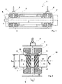
- a storage area 1 of an otherwise not shown turbocharger has at least one radial bearing 2,2 ', in which a rotor shaft 3 of a rotor 4 is rotatably mounted.
- the storage area 1 is surrounded by the bearing housing 5 of the exhaust gas turbocharger.
- the radial bearing 2, 2 ' has at least one fluid channel 6, with which fluid can be supplied to the layer region 7 or with which the fluid can be discharged from the layer region 7.
- a fluid film 8 is arranged, on which the rotor shaft 3 can slide.
- the fluid channel 6 is used inter alia with others in Fig. 1 Not shown means for continuous replacement of the fluid film 8.
- Via a fluid supply device 9,9 ' the fluid channel 6 and the radial bearing 2,2' are supplied with fluid.
- the fluid supply device 9,9 ' may be formed as a sickle groove.
- Fig. 2 is a section of the loading area 1 in the region of the radial bearing 2,2 'shown.
- a bearing shaft portion 10 of the rotor shaft 3 has a segment-like structure.
- an inner segment 11 is thus arranged on the rotor shaft 3.
- an outer segment 13, 13' is respectively arranged on the rotor shaft 3, so that the two outer segments 13, 13 'define the inner segment 11.
- the diameter of the rotor shaft 3 is denoted by D w and the diameter of the fluid channel 6 to D F.
- a plurality of transverse grooves 14 are positioned so that they are inclined with respect to the circumferential direction.
- the transverse grooves 14 in the direction of rotation 15 of the respective outer segment 13,13 'to the inner segment 11 extending.
- transverse grooves 14 extend straight here in a radial projection. Likewise, an embodiment is conceivable in which the transverse grooves 14 extend curved in a radial projection.
- a symmetrical embodiment of the transverse grooves 14 is shown, wherein the transverse grooves 14 with respect.
- the bearing center plane 16 are mirror image symmetrically positioned on the rotor shaft 3 in the bearing shaft portion 10.
- the fluid flow direction 17 extends from the inner segment 11 to the outer segments 13, 13 '.
- the length of the bearing shaft portion 10 is indicated by L W.
- Fig. 3 is a section of an outer segment 13,13 'shown.
- the fluid flow direction 17 is again running from the inner segment to the outer segment as shown and the direction of rotation 15 is analogous to the Fig. 2 , Furthermore, two sectional lines IV, V are shown, each in the FIGS. 4 and 5 are shown.
- Fig. 4a and 4b show two different embodiments of a transverse groove 14.
- Fig. 4a is shown in a rectangular shape while the Fig. 4b has a semicircular shape.
- the edges 18 of the transverse grooves 14 are provided with folds 19.
- the fold 19 may be formed as an edge break or rounding.
- the section V of Fig. 3 is in Fig. 5 shown. It shows a transverse groove 14, which is formed in the fluid flow direction 17 'within the transverse groove 14 with decreasing groove depth 20, 20'.
- 14 is also the distance in the transverse groove between the inner bearing portion 7 and the transverse groove bottom 21 in the fluid flow direction 17 decreasing.
- FIGS. 6a to 6d different embodiments of the bearing shaft portion 10 are shown.
- the fluid flow direction 17 extends from the inner segment 11 to the outer segments 13, 13 'and the direction of rotation 15 of the rotor shaft 3 as shown.
- the bearing center plane 16 is shown here a symmetrical embodiment. However, it is also an asymmetrical design conceivable, wherein the transverse grooves 14 are arranged offset from one another in the circumferential direction.
- This angle ⁇ may preferably have a value between 15 and 30 °, particularly preferably a value between 30 and 45 ° and very particularly preferably a value between 45 and 60 °.
- Fig. 6b shown embodiment is analogous to the embodiment of Fig. 6a constructed, with the only difference that the fluid flow direction 17 is oriented from the outer segment into the inner segment. As a result, the transverse grooves are running as shown.
- the Fig. 6c shows an embodiment of the bearing shaft portion 10 with a groove-free inner segment 11.
- the width of the inner segment is denoted by B i , while the widths of the outer segments with B a , B a 'are marked.
- the widths B a , B a 'of the outer segments are the same size.
- the embodiment of the Fig. 6d has an annular groove 23 extending over the entire inner segment region. Preference is given to the transverse grooves in a connection region 24,24 'of the respective outer segment 13,13' formed on the inner segment 11 so that they are fluidly connected to the annular groove 23.
- the deepest point of the transverse groove bottom 21 is preferably located at the level of the annular groove bottom 25.
- the transverse groove base 21 can be arranged below the annular groove bottom 25 viewed from the rotor shaft surface.
Landscapes
- Engineering & Computer Science (AREA)
- General Engineering & Computer Science (AREA)
- Mechanical Engineering (AREA)
- Chemical & Material Sciences (AREA)
- Oil, Petroleum & Natural Gas (AREA)
- Physics & Mathematics (AREA)
- Fluid Mechanics (AREA)
- Supercharger (AREA)
- Sliding-Contact Bearings (AREA)
- Support Of The Bearing (AREA)
Claims (9)
- Turbocompresseur à gaz d'échappement avec un arbre de rotor (3), qui est agencé mobile en rotation avec au moins un tronçon d'arbre de palier (10) dans un palier radial (2, 2') conçu sous forme de palier lisse et qui est agencé glissant sur un film fluide,- l'au moins un tronçon d'arbre de palier (10) étant divisé en deux segments externes (13, 13') agencés au niveau de la zone terminale de palier radial (12, 12') axiale respective et un segment interne (11) positionné entre les segments internes (13, 13'),- le segment interne (11) étant agencé globalement dans la zone d'une ouverture d'un canal de fluide (6) du palier radial (2, 2'),- au moins une rainure transversale (14) qui s'étend inclinée par rapport à la direction circonférentielle de l'arbre de rotor (3) étant agencée au moins dans l'un des segments externes (13, 13'),caractérisé en ce que- une profondeur de rainure (20, 20') d'au moins une rainure transversale (14) de ce type a une allure qui diminue de manière continue le long de la rainure transversale (14) dans une direction d'écoulement de fluide (17),- la distance entre l'axe de rotation d'arbre de rotor et la zone de surface de segment interne sans rainure transversale est inférieure à la distance entre l'axe de rotation d'arbre de rotor et une zone de surface de segment externe sans rainure transversale.
- Turbocompresseur à gaz d'échappement selon la revendication 1, caractérisé en ce que- pour une direction d'écoulement de fluide (17) allant du segment interne (11) aux segments externes (13, 13'), l'au moins une rainure transversale (14) s'étend, le long d'un sens de rotation (15) de l'arbre de rotor (3), du segment externe (13, 13') respectif au segment interne (11) ou,- pour une direction d'écoulement de fluide (17) allant des segments externes (13, 13') au segment interne (11), l'au moins une rainure transversale (14) s'étend, le long du sens de rotation (15), du segment interne (11) au segment externe (13, 13') respectif.
- Turbocompresseur à gaz d'échappement selon une ou plusieurs des revendications précédentes, caractérisé en ce que- au moins une rainure transversale (14) de ce type est agencée selon un angle prédéterminé β par rapport à une direction longitudinale (22), visualisée sur une surface d'arbre de rotor, de l'arbre de rotor (3).
- Turbocompresseur à gaz d'échappement selon une ou plusieurs des revendications précédentes, caractérisé en ce que- au moins une rainure transversale (14) de ce type pénètre dans le segment interne (11) et/ou- au moins deux rainures transversales (14) de ce type sont reliées l'une à l'autre dans le segment interne (14).
- Turbocompresseur à gaz d'échappement selon une ou plusieurs des revendications précédentes, caractérisé en ce que- une distance entre un axe de rotation d'arbre de rotor et une zone de surface de segment interne sans rainure transversale est égale à une distance entre l'axe de rotation d'arbre de rotor et une zone de surface de segment externe sans rainure transversale.
- Turbocompresseur à gaz d'échappement selon l'une des revendications 1 à 3, caractérisé en ce que- la distance entre l'axe de rotation d'arbre de rotor et la zone de surface de segment interne sans rainure transversale est égale à une distance entre l'axe de rotation d'arbre de rotor et le point le plus profond de l'au moins une rainure transversale (14) dans une zone de raccord (24) de celle-ci au segment interne (11).
- Turbocompresseur à gaz d'échappement selon une ou plusieurs des revendications précédentes, caractérisé en ce que- la profondeur de rainure (20, 20') d'au moins une rainure transversale (14) de ce type diminue le long d'une direction d'écoulement de fluide (17') à l'intérieur de la rainure transversale (14).
- Turbocompresseur à gaz d'échappement selon une ou plusieurs des revendications précédentes, caractérisé en ce que- les arêtes de rainure (18) d'au moins une rainure transversale (14) de ce type comportent un arrondi (19), un biseau (19) ou un chanfrein (19).
- Turbocompresseur à gaz d'échappement selon une ou plusieurs des revendications précédentes, caractérisé en ce que- la section transversale d'au moins une rainure transversale (14) de ce type est conçue rectangulaire et/ou au moins partiellement ellipsoïdale et/ou au moins partiellement demi-circulaire.
Applications Claiming Priority (2)
| Application Number | Priority Date | Filing Date | Title |
|---|---|---|---|
| DE102010022574A DE102010022574A1 (de) | 2010-06-02 | 2010-06-02 | Rotorwelle mit Gleitlager |
| PCT/EP2011/058526 WO2011151231A1 (fr) | 2010-06-02 | 2011-05-25 | Turbocompresseur à gaz d'échappement doté de paliers lisses pour diminuer les tourbillons de fluide |
Publications (2)
| Publication Number | Publication Date |
|---|---|
| EP2576996A1 EP2576996A1 (fr) | 2013-04-10 |
| EP2576996B1 true EP2576996B1 (fr) | 2015-07-15 |
Family
ID=44359492
Family Applications (1)
| Application Number | Title | Priority Date | Filing Date |
|---|---|---|---|
| EP11721317.3A Not-in-force EP2576996B1 (fr) | 2010-06-02 | 2011-05-25 | Turbocompresseur à gaz d'échappement doté de paliers lisses pour diminuer les tourbillons de fluide |
Country Status (4)
| Country | Link |
|---|---|
| US (1) | US20130129506A1 (fr) |
| EP (1) | EP2576996B1 (fr) |
| DE (1) | DE102010022574A1 (fr) |
| WO (1) | WO2011151231A1 (fr) |
Families Citing this family (9)
| Publication number | Priority date | Publication date | Assignee | Title |
|---|---|---|---|---|
| DE102010052892A1 (de) * | 2010-12-01 | 2012-06-06 | Voith Patent Gmbh | Lageranordnung für eine Welle eines Turbinenrades |
| DE102012202341A1 (de) * | 2012-02-16 | 2013-08-22 | Continental Automotive Gmbh | Radiallager für einen Abgasturbolader |
| CN104283344A (zh) * | 2014-05-28 | 2015-01-14 | 莱克电气股份有限公司 | 一种转子及其加工装配方法 |
| DE112015003803T5 (de) * | 2014-08-19 | 2017-05-04 | Borgwarner Inc. | Abgasturbolader |
| EP3315802A1 (fr) | 2016-10-31 | 2018-05-02 | Fischer Engineering Solutions AG | Système de rotation comprenant un palier à gaz axial |
| CN106763192B (zh) * | 2017-03-31 | 2022-05-27 | 河北工业大学 | 可承受径向和轴向力且具有自动换向供油功能的浮环轴承 |
| CN109751333B (zh) * | 2017-11-03 | 2023-04-14 | 台达电子工业股份有限公司 | 轴承结构 |
| EP3916252A1 (fr) * | 2020-05-28 | 2021-12-01 | Rolls-Royce Deutschland Ltd & Co KG | Système et procédé de surveillance d'un palier lisse |
| DE102022124129A1 (de) * | 2022-09-20 | 2024-03-21 | Zf Cv Systems Global Gmbh | Folienlager und Lagerbock zum Aufnehmen eines Folienlagers |
Family Cites Families (25)
| Publication number | Priority date | Publication date | Assignee | Title |
|---|---|---|---|---|
| NL145931B (nl) * | 1965-05-21 | 1975-05-15 | Tno | Inrichting voorzien van een aero- of hydrostatisch leger. |
| GB1316970A (en) * | 1969-08-26 | 1973-05-16 | Coventry Corp Of The City Of | Hydrostatic/hydrodynamic shaft bearing arrangements |
| NL7609817A (nl) * | 1976-09-03 | 1978-03-07 | Philips Nv | Lager. |
| US4366993A (en) * | 1980-01-07 | 1983-01-04 | Nippon Telegraph & Telephone Corp. | Gas bearings |
| JPS58149415A (ja) * | 1982-02-26 | 1983-09-05 | Hitachi Ltd | 制振軸受 |
| JPS5973624A (ja) * | 1982-10-18 | 1984-04-25 | Aisin Seiki Co Ltd | タ−ボチヤ−ジヤ用軸受装置 |
| JP2516967B2 (ja) * | 1987-04-30 | 1996-07-24 | 松下電器産業株式会社 | 軸受装置 |
| JPH044310A (ja) * | 1990-04-18 | 1992-01-08 | Matsushita Electric Ind Co Ltd | 動圧型気体軸受装置 |
| DE4230037A1 (de) * | 1991-09-09 | 1993-03-11 | Aisin Seiki | Zentrifugal-aufladegeblaese |
| JP2902262B2 (ja) * | 1993-03-29 | 1999-06-07 | 光洋精工株式会社 | 動圧軸受 |
| JPH07259849A (ja) * | 1994-03-24 | 1995-10-09 | Konica Corp | 動圧軸受 |
| US5483570A (en) * | 1994-06-24 | 1996-01-09 | General Electric Company | Bearings for x-ray tubes |
| US5941534A (en) * | 1994-10-12 | 1999-08-24 | Honda Giken Kogyo Kabushiki Kaisha | Hydraulic seal system |
| JP3069039B2 (ja) * | 1996-02-02 | 2000-07-24 | 日本電産コパル電子株式会社 | 動圧気体軸受 |
| US6427330B1 (en) * | 1997-10-07 | 2002-08-06 | Sankyo Seiki Mfg. Co., Ltd. | Method for forming a lubricant coating on a hydrodynamic bearing apparatus by electrode positioning |
| GB2335713A (en) * | 1998-03-27 | 1999-09-29 | Aisin Seiki | Air bearings and their use in hybrid charger |
| EP1024294A3 (fr) * | 1999-01-29 | 2002-03-13 | Ibiden Co., Ltd. | Moteur et pompe turbomoléculaire |
| JP3332357B2 (ja) * | 1999-07-26 | 2002-10-07 | 住友ゴム工業株式会社 | 空気入りタイヤ |
| EP1132633A4 (fr) * | 1999-09-17 | 2006-08-16 | Sumitomo Electric Industries | Palier a pression dynamique dote de caracteristiques de demarrage ameliorees |
| JP4152553B2 (ja) * | 2000-02-10 | 2008-09-17 | Thk株式会社 | タービンロータを備えたスピンドル装置 |
| JP4243928B2 (ja) * | 2002-02-06 | 2009-03-25 | Thk株式会社 | ロータ・ステータ型ホモジナイザー |
| US7448805B2 (en) * | 2004-11-02 | 2008-11-11 | Matsushita Electric Industrial Co., Ltd. | Thrust dynamic pressure bearing, spindle motor using thereof, and information recording/reproducing device using the spindle motor |
| TWI273187B (en) * | 2005-01-28 | 2007-02-11 | Foxconn Tech Co Ltd | Fluid dynamic bearing |
| US7637663B2 (en) * | 2006-06-15 | 2009-12-29 | Hitachi Global Storage Technologies Netherlands B.V. | Fluid bearing with a variable depth groove |
| US7670056B2 (en) | 2007-03-22 | 2010-03-02 | Honeywell International Inc. | Stepped outer diameter semi-floating bearing |
-
2010
- 2010-06-02 DE DE102010022574A patent/DE102010022574A1/de not_active Withdrawn
-
2011
- 2011-05-25 US US13/701,430 patent/US20130129506A1/en not_active Abandoned
- 2011-05-25 WO PCT/EP2011/058526 patent/WO2011151231A1/fr not_active Ceased
- 2011-05-25 EP EP11721317.3A patent/EP2576996B1/fr not_active Not-in-force
Also Published As
| Publication number | Publication date |
|---|---|
| DE102010022574A1 (de) | 2011-12-08 |
| US20130129506A1 (en) | 2013-05-23 |
| WO2011151231A1 (fr) | 2011-12-08 |
| EP2576996A1 (fr) | 2013-04-10 |
Similar Documents
| Publication | Publication Date | Title |
|---|---|---|
| EP2576996B1 (fr) | Turbocompresseur à gaz d'échappement doté de paliers lisses pour diminuer les tourbillons de fluide | |
| DE112015000855B4 (de) | Auswuchtverfahren für einen Turbolader | |
| DE69108523T2 (de) | Lager für Turbolader. | |
| EP1355043A1 (fr) | Aube de rotor pour une turbomachine | |
| EP2002126A2 (fr) | Pompe centrifuge à accouplement magnétique coaxial | |
| DE112013001368T5 (de) | Turbolader mit Axiallager zur Bereitstellung von kombinierten Zapfen- und Axiallager-Funktionen | |
| EP3762624B1 (fr) | Turbocompresseur à gaz d'échappement doté d'un palier lisse hydrodynamique ou arrangement de palier doté d'un palier lisse hydrodynamique | |
| EP2884054A1 (fr) | Aube de guidage variable avec cône tronqué dans un ensemble palier | |
| DE3840487A1 (de) | Dichtung fuer eine zylinderflaeche | |
| EP2599979B1 (fr) | Turbocompresseur | |
| DE102008060369A1 (de) | Hydrodynamische Radialgleitlagerung | |
| EP2716874B1 (fr) | Stator, procédé de montage et turbomachine | |
| WO2014044363A1 (fr) | Dispositif formant palier ainsi que turbocompresseur | |
| DE102016222625A1 (de) | Lagerbuchse für eine Welle eines Turboladers | |
| EP2994615A1 (fr) | Rotor pour turbomachine thermique | |
| DE102017207173B4 (de) | Turbolader mit Sollbruchstelle für eine Brennkraftmaschine | |
| DE202017100779U1 (de) | Ölabscheider mit geteilter Antriebskammer | |
| DE102012202341A1 (de) | Radiallager für einen Abgasturbolader | |
| DE102008033814A1 (de) | Lagerabschnitt für einen Abgasturbolader und Abgasturbolader | |
| DE112018004771T5 (de) | Turbolader | |
| EP3601739B1 (fr) | Turbocompresseur pour un moteur à combustion interne ainsi que roue de turbine | |
| DE102016113718B3 (de) | Gleitgelagerte doppelwandige Rotornabe für eine Windenergieanlage | |
| DE112021003728B4 (de) | Lager und Turbolader | |
| WO2013182306A1 (fr) | Système d'étanchéité hydraulique | |
| EP3792451B1 (fr) | Étage de compresseur à inclinaison variable des pales de stator |
Legal Events
| Date | Code | Title | Description |
|---|---|---|---|
| PUAI | Public reference made under article 153(3) epc to a published international application that has entered the european phase |
Free format text: ORIGINAL CODE: 0009012 |
|
| 17P | Request for examination filed |
Effective date: 20121115 |
|
| AK | Designated contracting states |
Kind code of ref document: A1 Designated state(s): AL AT BE BG CH CY CZ DE DK EE ES FI FR GB GR HR HU IE IS IT LI LT LU LV MC MK MT NL NO PL PT RO RS SE SI SK SM TR |
|
| DAX | Request for extension of the european patent (deleted) | ||
| GRAP | Despatch of communication of intention to grant a patent |
Free format text: ORIGINAL CODE: EPIDOSNIGR1 |
|
| INTG | Intention to grant announced |
Effective date: 20150310 |
|
| GRAS | Grant fee paid |
Free format text: ORIGINAL CODE: EPIDOSNIGR3 |
|
| GRAA | (expected) grant |
Free format text: ORIGINAL CODE: 0009210 |
|
| AK | Designated contracting states |
Kind code of ref document: B1 Designated state(s): AL AT BE BG CH CY CZ DE DK EE ES FI FR GB GR HR HU IE IS IT LI LT LU LV MC MK MT NL NO PL PT RO RS SE SI SK SM TR |
|
| REG | Reference to a national code |
Ref country code: CH Ref legal event code: EP Ref country code: GB Ref legal event code: FG4D Free format text: NOT ENGLISH |
|
| REG | Reference to a national code |
Ref country code: IE Ref legal event code: FG4D Free format text: LANGUAGE OF EP DOCUMENT: GERMAN |
|
| REG | Reference to a national code |
Ref country code: AT Ref legal event code: REF Ref document number: 736920 Country of ref document: AT Kind code of ref document: T Effective date: 20150815 |
|
| REG | Reference to a national code |
Ref country code: DE Ref legal event code: R096 Ref document number: 502011007335 Country of ref document: DE |
|
| REG | Reference to a national code |
Ref country code: NL Ref legal event code: MP Effective date: 20150715 |
|
| REG | Reference to a national code |
Ref country code: LT Ref legal event code: MG4D |
|
| PG25 | Lapsed in a contracting state [announced via postgrant information from national office to epo] |
Ref country code: GR Free format text: LAPSE BECAUSE OF FAILURE TO SUBMIT A TRANSLATION OF THE DESCRIPTION OR TO PAY THE FEE WITHIN THE PRESCRIBED TIME-LIMIT Effective date: 20151016 Ref country code: LT Free format text: LAPSE BECAUSE OF FAILURE TO SUBMIT A TRANSLATION OF THE DESCRIPTION OR TO PAY THE FEE WITHIN THE PRESCRIBED TIME-LIMIT Effective date: 20150715 Ref country code: LV Free format text: LAPSE BECAUSE OF FAILURE TO SUBMIT A TRANSLATION OF THE DESCRIPTION OR TO PAY THE FEE WITHIN THE PRESCRIBED TIME-LIMIT Effective date: 20150715 Ref country code: FI Free format text: LAPSE BECAUSE OF FAILURE TO SUBMIT A TRANSLATION OF THE DESCRIPTION OR TO PAY THE FEE WITHIN THE PRESCRIBED TIME-LIMIT Effective date: 20150715 Ref country code: NO Free format text: LAPSE BECAUSE OF FAILURE TO SUBMIT A TRANSLATION OF THE DESCRIPTION OR TO PAY THE FEE WITHIN THE PRESCRIBED TIME-LIMIT Effective date: 20151015 |
|
| PG25 | Lapsed in a contracting state [announced via postgrant information from national office to epo] |
Ref country code: PL Free format text: LAPSE BECAUSE OF FAILURE TO SUBMIT A TRANSLATION OF THE DESCRIPTION OR TO PAY THE FEE WITHIN THE PRESCRIBED TIME-LIMIT Effective date: 20150715 Ref country code: RS Free format text: LAPSE BECAUSE OF FAILURE TO SUBMIT A TRANSLATION OF THE DESCRIPTION OR TO PAY THE FEE WITHIN THE PRESCRIBED TIME-LIMIT Effective date: 20150715 Ref country code: HR Free format text: LAPSE BECAUSE OF FAILURE TO SUBMIT A TRANSLATION OF THE DESCRIPTION OR TO PAY THE FEE WITHIN THE PRESCRIBED TIME-LIMIT Effective date: 20150715 Ref country code: ES Free format text: LAPSE BECAUSE OF FAILURE TO SUBMIT A TRANSLATION OF THE DESCRIPTION OR TO PAY THE FEE WITHIN THE PRESCRIBED TIME-LIMIT Effective date: 20150715 Ref country code: SE Free format text: LAPSE BECAUSE OF FAILURE TO SUBMIT A TRANSLATION OF THE DESCRIPTION OR TO PAY THE FEE WITHIN THE PRESCRIBED TIME-LIMIT Effective date: 20150715 Ref country code: PT Free format text: LAPSE BECAUSE OF FAILURE TO SUBMIT A TRANSLATION OF THE DESCRIPTION OR TO PAY THE FEE WITHIN THE PRESCRIBED TIME-LIMIT Effective date: 20151116 |
|
| REG | Reference to a national code |
Ref country code: DE Ref legal event code: R097 Ref document number: 502011007335 Country of ref document: DE |
|
| PG25 | Lapsed in a contracting state [announced via postgrant information from national office to epo] |
Ref country code: CZ Free format text: LAPSE BECAUSE OF FAILURE TO SUBMIT A TRANSLATION OF THE DESCRIPTION OR TO PAY THE FEE WITHIN THE PRESCRIBED TIME-LIMIT Effective date: 20150715 Ref country code: SK Free format text: LAPSE BECAUSE OF FAILURE TO SUBMIT A TRANSLATION OF THE DESCRIPTION OR TO PAY THE FEE WITHIN THE PRESCRIBED TIME-LIMIT Effective date: 20150715 Ref country code: IT Free format text: LAPSE BECAUSE OF FAILURE TO SUBMIT A TRANSLATION OF THE DESCRIPTION OR TO PAY THE FEE WITHIN THE PRESCRIBED TIME-LIMIT Effective date: 20150715 Ref country code: EE Free format text: LAPSE BECAUSE OF FAILURE TO SUBMIT A TRANSLATION OF THE DESCRIPTION OR TO PAY THE FEE WITHIN THE PRESCRIBED TIME-LIMIT Effective date: 20150715 Ref country code: DK Free format text: LAPSE BECAUSE OF FAILURE TO SUBMIT A TRANSLATION OF THE DESCRIPTION OR TO PAY THE FEE WITHIN THE PRESCRIBED TIME-LIMIT Effective date: 20150715 |
|
| PLBE | No opposition filed within time limit |
Free format text: ORIGINAL CODE: 0009261 |
|
| STAA | Information on the status of an ep patent application or granted ep patent |
Free format text: STATUS: NO OPPOSITION FILED WITHIN TIME LIMIT |
|
| PG25 | Lapsed in a contracting state [announced via postgrant information from national office to epo] |
Ref country code: RO Free format text: LAPSE BECAUSE OF FAILURE TO SUBMIT A TRANSLATION OF THE DESCRIPTION OR TO PAY THE FEE WITHIN THE PRESCRIBED TIME-LIMIT Effective date: 20150715 |
|
| REG | Reference to a national code |
Ref country code: FR Ref legal event code: PLFP Year of fee payment: 6 |
|
| 26N | No opposition filed |
Effective date: 20160418 |
|
| PG25 | Lapsed in a contracting state [announced via postgrant information from national office to epo] |
Ref country code: IS Free format text: LAPSE BECAUSE OF FAILURE TO SUBMIT A TRANSLATION OF THE DESCRIPTION OR TO PAY THE FEE WITHIN THE PRESCRIBED TIME-LIMIT Effective date: 20150715 |
|
| PG25 | Lapsed in a contracting state [announced via postgrant information from national office to epo] |
Ref country code: BE Free format text: LAPSE BECAUSE OF NON-PAYMENT OF DUE FEES Effective date: 20160531 Ref country code: SI Free format text: LAPSE BECAUSE OF FAILURE TO SUBMIT A TRANSLATION OF THE DESCRIPTION OR TO PAY THE FEE WITHIN THE PRESCRIBED TIME-LIMIT Effective date: 20150715 |
|
| PG25 | Lapsed in a contracting state [announced via postgrant information from national office to epo] |
Ref country code: LU Free format text: LAPSE BECAUSE OF FAILURE TO SUBMIT A TRANSLATION OF THE DESCRIPTION OR TO PAY THE FEE WITHIN THE PRESCRIBED TIME-LIMIT Effective date: 20160525 |
|
| REG | Reference to a national code |
Ref country code: CH Ref legal event code: PL |
|
| PG25 | Lapsed in a contracting state [announced via postgrant information from national office to epo] |
Ref country code: LI Free format text: LAPSE BECAUSE OF NON-PAYMENT OF DUE FEES Effective date: 20160531 Ref country code: CH Free format text: LAPSE BECAUSE OF NON-PAYMENT OF DUE FEES Effective date: 20160531 |
|
| REG | Reference to a national code |
Ref country code: IE Ref legal event code: MM4A |
|
| REG | Reference to a national code |
Ref country code: FR Ref legal event code: PLFP Year of fee payment: 7 |
|
| PG25 | Lapsed in a contracting state [announced via postgrant information from national office to epo] |
Ref country code: IE Free format text: LAPSE BECAUSE OF NON-PAYMENT OF DUE FEES Effective date: 20160525 |
|
| PG25 | Lapsed in a contracting state [announced via postgrant information from national office to epo] |
Ref country code: NL Free format text: LAPSE BECAUSE OF FAILURE TO SUBMIT A TRANSLATION OF THE DESCRIPTION OR TO PAY THE FEE WITHIN THE PRESCRIBED TIME-LIMIT Effective date: 20150715 |
|
| REG | Reference to a national code |
Ref country code: AT Ref legal event code: MM01 Ref document number: 736920 Country of ref document: AT Kind code of ref document: T Effective date: 20160525 |
|
| PG25 | Lapsed in a contracting state [announced via postgrant information from national office to epo] |
Ref country code: AT Free format text: LAPSE BECAUSE OF NON-PAYMENT OF DUE FEES Effective date: 20160525 |
|
| REG | Reference to a national code |
Ref country code: FR Ref legal event code: PLFP Year of fee payment: 8 |
|
| PG25 | Lapsed in a contracting state [announced via postgrant information from national office to epo] |
Ref country code: HU Free format text: LAPSE BECAUSE OF FAILURE TO SUBMIT A TRANSLATION OF THE DESCRIPTION OR TO PAY THE FEE WITHIN THE PRESCRIBED TIME-LIMIT; INVALID AB INITIO Effective date: 20110525 Ref country code: SM Free format text: LAPSE BECAUSE OF FAILURE TO SUBMIT A TRANSLATION OF THE DESCRIPTION OR TO PAY THE FEE WITHIN THE PRESCRIBED TIME-LIMIT Effective date: 20150715 Ref country code: CY Free format text: LAPSE BECAUSE OF FAILURE TO SUBMIT A TRANSLATION OF THE DESCRIPTION OR TO PAY THE FEE WITHIN THE PRESCRIBED TIME-LIMIT Effective date: 20150715 |
|
| REG | Reference to a national code |
Ref country code: DE Ref legal event code: R082 Ref document number: 502011007335 Country of ref document: DE Representative=s name: BRP RENAUD UND PARTNER MBB RECHTSANWAELTE PATE, DE Ref country code: DE Ref legal event code: R081 Ref document number: 502011007335 Country of ref document: DE Owner name: BMTS TECHNOLOGY GMBH & CO. KG, DE Free format text: FORMER OWNER: BOSCH MAHLE TURBO SYSTEMS GMBH & CO. KG, 70376 STUTTGART, DE |
|
| PG25 | Lapsed in a contracting state [announced via postgrant information from national office to epo] |
Ref country code: MT Free format text: LAPSE BECAUSE OF FAILURE TO SUBMIT A TRANSLATION OF THE DESCRIPTION OR TO PAY THE FEE WITHIN THE PRESCRIBED TIME-LIMIT Effective date: 20150715 Ref country code: TR Free format text: LAPSE BECAUSE OF FAILURE TO SUBMIT A TRANSLATION OF THE DESCRIPTION OR TO PAY THE FEE WITHIN THE PRESCRIBED TIME-LIMIT Effective date: 20150715 Ref country code: MC Free format text: LAPSE BECAUSE OF FAILURE TO SUBMIT A TRANSLATION OF THE DESCRIPTION OR TO PAY THE FEE WITHIN THE PRESCRIBED TIME-LIMIT Effective date: 20150715 Ref country code: MK Free format text: LAPSE BECAUSE OF FAILURE TO SUBMIT A TRANSLATION OF THE DESCRIPTION OR TO PAY THE FEE WITHIN THE PRESCRIBED TIME-LIMIT Effective date: 20150715 |
|
| PG25 | Lapsed in a contracting state [announced via postgrant information from national office to epo] |
Ref country code: BG Free format text: LAPSE BECAUSE OF FAILURE TO SUBMIT A TRANSLATION OF THE DESCRIPTION OR TO PAY THE FEE WITHIN THE PRESCRIBED TIME-LIMIT Effective date: 20150715 |
|
| PG25 | Lapsed in a contracting state [announced via postgrant information from national office to epo] |
Ref country code: AL Free format text: LAPSE BECAUSE OF FAILURE TO SUBMIT A TRANSLATION OF THE DESCRIPTION OR TO PAY THE FEE WITHIN THE PRESCRIBED TIME-LIMIT Effective date: 20150715 |
|
| PGFP | Annual fee paid to national office [announced via postgrant information from national office to epo] |
Ref country code: FR Payment date: 20200528 Year of fee payment: 10 |
|
| PGFP | Annual fee paid to national office [announced via postgrant information from national office to epo] |
Ref country code: GB Payment date: 20200528 Year of fee payment: 10 |
|
| PGFP | Annual fee paid to national office [announced via postgrant information from national office to epo] |
Ref country code: DE Payment date: 20200728 Year of fee payment: 10 |
|
| REG | Reference to a national code |
Ref country code: DE Ref legal event code: R119 Ref document number: 502011007335 Country of ref document: DE |
|
| GBPC | Gb: european patent ceased through non-payment of renewal fee |
Effective date: 20210525 |
|
| PG25 | Lapsed in a contracting state [announced via postgrant information from national office to epo] |
Ref country code: GB Free format text: LAPSE BECAUSE OF NON-PAYMENT OF DUE FEES Effective date: 20210525 Ref country code: DE Free format text: LAPSE BECAUSE OF NON-PAYMENT OF DUE FEES Effective date: 20211201 |
|
| PG25 | Lapsed in a contracting state [announced via postgrant information from national office to epo] |
Ref country code: FR Free format text: LAPSE BECAUSE OF NON-PAYMENT OF DUE FEES Effective date: 20210531 |