EP2002929B1 - Vorrichtung zur Glättung eines Produkts, im Besonderen eines halbfertigen Keramikprodukts - Google Patents
Vorrichtung zur Glättung eines Produkts, im Besonderen eines halbfertigen Keramikprodukts Download PDFInfo
- Publication number
- EP2002929B1 EP2002929B1 EP08153705A EP08153705A EP2002929B1 EP 2002929 B1 EP2002929 B1 EP 2002929B1 EP 08153705 A EP08153705 A EP 08153705A EP 08153705 A EP08153705 A EP 08153705A EP 2002929 B1 EP2002929 B1 EP 2002929B1
- Authority
- EP
- European Patent Office
- Prior art keywords
- belt
- arm
- roller
- negative pressure
- way
- Prior art date
- Legal status (The legal status is an assumption and is not a legal conclusion. Google has not performed a legal analysis and makes no representation as to the accuracy of the status listed.)
- Active
Links
- 238000009499 grossing Methods 0.000 title claims description 24
- 239000000919 ceramic Substances 0.000 title claims description 7
- 238000005507 spraying Methods 0.000 claims description 21
- 239000007788 liquid Substances 0.000 claims description 19
- 238000000034 method Methods 0.000 claims description 17
- 230000008569 process Effects 0.000 claims description 15
- 239000002699 waste material Substances 0.000 claims description 11
- 239000000463 material Substances 0.000 claims description 7
- 230000033001 locomotion Effects 0.000 claims description 4
- 230000000717 retained effect Effects 0.000 claims description 4
- 230000001172 regenerating effect Effects 0.000 claims description 3
- 238000010521 absorption reaction Methods 0.000 claims description 2
- 230000002146 bilateral effect Effects 0.000 claims description 2
- 230000006835 compression Effects 0.000 claims description 2
- 238000007906 compression Methods 0.000 claims description 2
- 230000005484 gravity Effects 0.000 claims description 2
- 238000011144 upstream manufacturing Methods 0.000 claims description 2
- 239000000047 product Substances 0.000 description 35
- XLYOFNOQVPJJNP-UHFFFAOYSA-N water Substances O XLYOFNOQVPJJNP-UHFFFAOYSA-N 0.000 description 6
- 230000008901 benefit Effects 0.000 description 5
- 239000011265 semifinished product Substances 0.000 description 3
- 238000005266 casting Methods 0.000 description 2
- 239000012636 effector Substances 0.000 description 2
- 238000005516 engineering process Methods 0.000 description 2
- 238000009434 installation Methods 0.000 description 2
- 239000010985 leather Substances 0.000 description 2
- 238000004519 manufacturing process Methods 0.000 description 2
- 230000007935 neutral effect Effects 0.000 description 2
- 230000008929 regeneration Effects 0.000 description 2
- 238000011069 regeneration method Methods 0.000 description 2
- 230000009471 action Effects 0.000 description 1
- 230000005540 biological transmission Effects 0.000 description 1
- 229910010293 ceramic material Inorganic materials 0.000 description 1
- 230000008859 change Effects 0.000 description 1
- 230000009849 deactivation Effects 0.000 description 1
- 230000000694 effects Effects 0.000 description 1
- 239000012530 fluid Substances 0.000 description 1
- 238000012423 maintenance Methods 0.000 description 1
- 239000000203 mixture Substances 0.000 description 1
- 238000000465 moulding Methods 0.000 description 1
- 239000002245 particle Substances 0.000 description 1
- 239000002994 raw material Substances 0.000 description 1
- 238000007569 slipcasting Methods 0.000 description 1
- 239000007787 solid Substances 0.000 description 1
- 239000007921 spray Substances 0.000 description 1
- 230000003068 static effect Effects 0.000 description 1
- 239000000725 suspension Substances 0.000 description 1
Images


Classifications
-
- B—PERFORMING OPERATIONS; TRANSPORTING
- B24—GRINDING; POLISHING
- B24B—MACHINES, DEVICES, OR PROCESSES FOR GRINDING OR POLISHING; DRESSING OR CONDITIONING OF ABRADING SURFACES; FEEDING OF GRINDING, POLISHING, OR LAPPING AGENTS
- B24B19/00—Single-purpose machines or devices for particular grinding operations not covered by any other main group
- B24B19/008—Single-purpose machines or devices for particular grinding operations not covered by any other main group for grinding ceramics, pottery, table ware
-
- B—PERFORMING OPERATIONS; TRANSPORTING
- B24—GRINDING; POLISHING
- B24B—MACHINES, DEVICES, OR PROCESSES FOR GRINDING OR POLISHING; DRESSING OR CONDITIONING OF ABRADING SURFACES; FEEDING OF GRINDING, POLISHING, OR LAPPING AGENTS
- B24B21/00—Machines or devices using grinding or polishing belts; Accessories therefor
- B24B21/16—Machines or devices using grinding or polishing belts; Accessories therefor for grinding other surfaces of particular shape
-
- B—PERFORMING OPERATIONS; TRANSPORTING
- B24—GRINDING; POLISHING
- B24B—MACHINES, DEVICES, OR PROCESSES FOR GRINDING OR POLISHING; DRESSING OR CONDITIONING OF ABRADING SURFACES; FEEDING OF GRINDING, POLISHING, OR LAPPING AGENTS
- B24B55/00—Safety devices for grinding or polishing machines; Accessories fitted to grinding or polishing machines for keeping tools or parts of the machine in good working condition
- B24B55/06—Dust extraction equipment on grinding or polishing machines
- B24B55/08—Dust extraction equipment on grinding or polishing machines specially designed for belt grinding machines
-
- B—PERFORMING OPERATIONS; TRANSPORTING
- B28—WORKING CEMENT, CLAY, OR STONE
- B28B—SHAPING CLAY OR OTHER CERAMIC COMPOSITIONS; SHAPING SLAG; SHAPING MIXTURES CONTAINING CEMENTITIOUS MATERIAL, e.g. PLASTER
- B28B11/00—Apparatus or processes for treating or working the shaped or preshaped articles
- B28B11/08—Apparatus or processes for treating or working the shaped or preshaped articles for reshaping the surface, e.g. smoothing, roughening, corrugating, making screw-threads
- B28B11/0845—Apparatus or processes for treating or working the shaped or preshaped articles for reshaping the surface, e.g. smoothing, roughening, corrugating, making screw-threads for smoothing
Definitions
- This invention relates preferably to ceramics technology for the manufacture of ceramic products by casting a suspension in water of a clayey raw material (known as "slip") in porous moulds to obtain semi-finished sanitaryware such as washbasins, bidets and similar articles.
- a clayey raw material known as "slip”
- the invention relates in particular to an apparatus for finishing these products by smoothing their surfaces during the manufacturing process while they are still in “states” that allow abrasive means to be used on them with the aid of liquids to facilitate their machinability, that is to say, when they are in the "green” and “leather hard” states.
- the surface smoothing of semi-finished ceramic products obtained by slip casting is preferably performed when the products are in the "green” state (that is to say, solid but still having a water content of between 17% and 20% by weight - and hence still subject to plastic deformation) or in the "leather hard” state (with a water content normally less than 13%, where the product, although rigid, can still be worked with a wet smoothing tool).
- smoothing can also be performed when the product is already in the "dry” state, that is, having a water content normally below 2%.
- a prior art apparatus - described in document EP 640.450 - comprises a finishing tool that can be automatically regenerated continuously while working.
- the tool comprises a power-driven endless abrasive belt trained around three pulleys positioned in space in such a way as to subtend the belt to a form closed, three-sided figure comprising an active section, a passive section and a transmission section.
- the passive section is associated with a tank containing a liquid through which the passive section moves and remains permanently dipped.
- the semi-finished product to be smoothed held by a robot-controlled mechanical manipulator, is suitably oriented in space and moved into contact with the active belt section which slides tangentially over the surface of the semi-finished product to remove burs and other surface irregularities.
- the particles of ceramic material removed are trapped in the material structure of the abrasive belt's active section and are washed away when the active section moves on to become the passive section and is dipped into the tank.
- the method described above has inherent disadvantages, one of which is the fact that it involves moving the semi-finished product and keeping the smoothing apparatus stationary, the apparatus being much lighter in weight than the product.
- Another disadvantage is that smoothing using the method described above is relatively easy if the surfaces to be smoothed are convex but, on the contrary, is considerably difficult, or even impossible, if the surfaces are concave.
- the patterns of motion involved in the manipulation of the product may be very complicated, which means that the parts of the product that come into contact with the robot are subjected to stress that is not always negligible and are therefore liable to damage.
- rotary tools such as cylindrical sponges
- These tools are rotated while the product (especially "greenware") is held stationary in a predetermined position.
- the smoothing apparatus according to the invention, labelled 1 in its entirety, is used to smooth a product 2 (illustrated schematically since it does not strictly form part of the invention), in particular, a semi-finished ceramic product obtained by casting a liquid mixture (known as "slip" in the jargon of the trade) in a moulding cavity formed by at least two parts of a mould.
- a product 2 illustrated schematically since it does not strictly form part of the invention
- a semi-finished ceramic product obtained by casting a liquid mixture (known as "slip" in the jargon of the trade) in a moulding cavity formed by at least two parts of a mould.
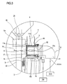
- the apparatus 1 basically comprises an abrasive tool 3 in the form of an endless belt 4 which (in the embodiment illustrated) is trained around at least one pair of pulleys 5 and 6, at least one which is power-driven (by a respective motor 5m), and which defines an active section 7 and a passive section 8 of the belt 4:
- the apparatus 1 also comprises:
- the means 20 enable the apparatus 1 to be associated with a manipulator 21, preferably robot-controlled (partly illustrated since it is of known type).
- the above mentioned structure 20 may comprise a swinging mounting arm 22 (see arrow F22) pivoted at 22a to a support 23 connected to flanged means 24 for connection to the manual or robot-controlled manipulator 21.
- the lower pulley 6 of the belt 4 is rotatably connected to the first arm 22, at the lower end of the first arm 22.
- the upper end of the arm 22 is associated with a counterweight 25 for balancing the centre of gravity of the first arm 22 itself, and hence of the belt 4: in this way, the belt 4 is kept in a neutral positional configuration independent of the position adopted by the apparatus 1 as a whole. In other words, the belt 4 and the first arm 22 remain in a static, substantially stationary, configuration, especially during movements towards and away from the product 2.
- the first arm 22 is also provided with adjustable limit stop and contact means 26 acting between the first arm 22 and the support 23 and designed to permit adjustment of at least one stable end position where the first arm 22 is angularly closest to the support 23 and where movement towards the belt 4 is stopped when the belt 4 comes into contact with the product 2.
- the invention contemplates the provision of pushing means 100 composed of a cylinder 101 mounted on the support 23 and acting on a roller 102 that is keyed to the first arm 22 and positioned eccentrically with respect to its pivot point 22a: in this way, the active section 7 of the belt 4 may apply a predetermined contact force on the product 2, even in combination with the manipulator 21, according to the pushing force exerted by the cylinder 101 (see arrow F101) on the eccentric roller 102.
- the numeral 103 indicates a block (see Figure 1 ) representing control means acting on the cylinder 101 and designed to activate and deactivate the cylinder 101, when required, deactivation of the cylinder 101, obviously, causing the first arm 22 to return to a neutral position.
- the limit stop and contact means 26 are located at two different points of the first arm 22 and each consists of a threaded rod 27 protruding transversally from the first arm 22 and screwed into a respective hole 28 made in the first arm 22.
- Each of the rods 27 has an end head 29 designed to come into contact, in use, with respective zones of the support 23.
- the above mentioned lower pulley 6 is connected by its mounting shaft 6a, to the inside of a slot 30 made in the first arm 22 and in such a way that, when required, it can be moved (arrow F30) to adjust the tension of the belt 4 by slackening the shaft 6a from the slot 30 and, if necessary, to change the belt 4 itself.
- the above mentioned upper pulley 5 of the belt 4 is connected to its drive 5m which is in turn mounted on a bracket 32 protruding from the first arm 22.
- the belt 4 is made of a material that absorbs liquid - for example water - which is sprayed on the belt 4 by the above mentioned spraying means 10 which the apparatus 1 is equipped with.
- the liquid spraying means 10 are located in the vicinity of the belt 4 itself.
- the means 10 may be mounted directly on contact means 18 (described in more detail below) and comprise nozzles for spraying liquid on the belt 4.
- the spray means 10 may consist of a plurality of nozzles 10a, fed by a respective source 10b, positioned upstream of the negative pressure means 9 relative to a direction of rotation (indicated by the arrow S) of the belt 4 in such a way that they face a portion of the passive section 8 of the belt 4.
- the apparatus 1 also comprises negative pressure means 9 which are associated with the passive section 8 of the belt 4 and which are designed to remove from the belt 4 the liquid sprayed onto it by the spraying means 10 together with the process waste material removed and retained by the belt 4 during the active stage of the smoothing process and transferred to the passive stage of the smoothing process.
- the negative pressure means 9 include, in particular, a roller 11 which rotates freely about its axis of rotation 15 and which is in direct, tangential contact with the passive section 8 of the belt 4.
- the roller 11 cylindrical in shape, is rotatably coupled coaxially with a hollow pin 17 that defines a cavity 12 inside it.
- the roller 11 also has a cylindrical outside lateral operating surface 11a provided with a plurality of through holes 11b designed to allow the outside and the inside of the cavity 12 to communicate through a slot 17c formed on the hollow pin 17 in such a way as to face the passive section 8 of the belt 4.
- the lateral surface 11a of the roller 11 has shoulders 16 having an enveloping shape matching the opposite longitudinal edges of the belt 4.
- the cavity 12 inside the hollow pin 17 is designed to suck the liquid and the smoothing process waste material out through the roller 11, that is to say, through the holes 11b in the lateral surface 11a and through the slot 17c; the suction being produced by: the negative pressure created inside the cavity 12 by the fluid connection of the cavity 12 with vacuum generating means 31m such as, for example, a vacuum pump, represented as a block in Figure 3 since they are entirely conventional; as well as by the direct connection of the cavity 12 with the holes 11b, through the slot 17c in the pin 17.
- vacuum generating means 31m such as, for example, a vacuum pump, represented as a block in Figure 3 since they are entirely conventional
- the roller 11 turns freely together with the belt 4 and when the portion of the roller 11 surface with the holes 11b comes into contact with the passive section 8 and the holes coincide with the slot 17c, the process waste material is removed from the passive section 8 by the suction produced.
- the roller 11 is held in direct, forced contact with the belt 4 by contact means 18 which include a mounting arm 18a and elastic elements 19 interposed between the roller 11 and the first arm 22 and which operate in such a way as to compress the roller 11 against the belt 4 so as to maximize the effect of the seal and, hence, the effectiveness of suction.
- contact means 18 which include a mounting arm 18a and elastic elements 19 interposed between the roller 11 and the first arm 22 and which operate in such a way as to compress the roller 11 against the belt 4 so as to maximize the effect of the seal and, hence, the effectiveness of suction.
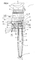
- Figures 4 to 7 illustrate a second embodiment of the apparatus 1.
- the belt 4 mounting structure 20 comprises:
- the support 35 also has in the middle of it an auxiliary idle wheel 36 that is rotatably connected to the support 35 and in bilateral contact with a protruding internal profile of the belt 4 in such a way as to enable the latter to slide more easily.
- the spraying means 10, the negative pressure means 9, the upper pulley 5 and the related drive 5m are mounted on a first member 60 located inside the frame 33 and pivoted at end of it and at 60a to the frame 33 itself.
- the member 60 is acted upon by tensioning means 61, composed of a cylinder 62 located at the bottom of the frame 33, protruding vertically inside the frame 33 and acting on an idle roller 63 connected, at 63a, to the member 60 and positioned eccentrically with respect to the pivot point 60a of the member: in this way, moving the member 60 up or down (see arrow F60, Figure 4 ) moves the upper pulley 5 in such a way as to tension or slacken the belt 4.
- tensioning means 61 composed of a cylinder 62 located at the bottom of the frame 33, protruding vertically inside the frame 33 and acting on an idle roller 63 connected, at 63a, to the member 60 and positioned eccentrically with respect to the pivot point 60a of the member: in this way, moving the member 60 up or down (see arrow F60, Figure 4 ) moves the upper pulley 5 in such a way as to tension or slacken the belt 4.
- the numeral 64 indicates a block (see Figures 4 to 7 ) representing control means acting on the cylinder 62 and designed to activate and deactivate the cylinder 62, when required and in such a way as to control the force applied by the cylinder 62 to the roller 63, thus keeping the tension of the belt 4 under control.
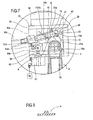
- the spraying means 10 and the negative pressure means 9 are made in a portion 37 of the member 60 that is pivoted at 37a to the member 60 itself, in such a way as to enable the portion 37 to rotate between:
- the negative pressure means 9 are composed of a closed cylindrical chamber 65 provided with a slit 65a (see Figure 7 ) that can be positioned to face the passive section 8 of the belt 4 when the portion 37 is in the lowered position.
- the negative pressure is generated in the chamber 65 using suitable means 65b which, in this case, purely by way of example, are embodied by a Venturi unit, partly illustrated in Figure 7 , through which the process waste material is removed by suction, channelled into the pipe 65c (see arrow F65c) and then expelled.
- suitable means 65b which, in this case, purely by way of example, are embodied by a Venturi unit, partly illustrated in Figure 7 , through which the process waste material is removed by suction, channelled into the pipe 65c (see arrow F65c) and then expelled.
- the spraying means 10 comprise two sets of nozzles 10a made on the portion 37 on opposite sides of the cylindrical chamber 65: the liquid supply means 10b are, obviously, activated by one or the other of the sets of nozzles 10a depending on the rotation direction S of the belt 4 and in such a way that the belt 4 is always sprayed before it moves past the cylindrical chamber 65: that means the belt 4 can operate in both directions of rotation.
- Means 38 are provided between the portion 37 and the member 60 for locking the containing portion 37 in the lowered operating position so that it can be positioned stably over the belt 4.
- the locking means 38 comprise a vertical lever 39 pivoted at one of it, at 39a, to the member 60 and snappingly engageable, at it its free opposite end, with a pin 40 that protrudes laterally from the portion 37 and that can be positioned near the lever 39 when the portion 37 is in the lowered operating position.
- An elastic element 41 is interposed between the lever 39 and the member 60 so as to keep the lever 39 constantly in contact with the pin 40.
- adjustable limit stop means 70 are provided between the portion 37 and the member 60: the means 70 comprise a bolt 70a screwed into a threaded through hole made in the portion 37 in such a way that its lower end comes into contact with a surface of the member 60 when the portion 37 is in the lowered position.
- Screwing or unscrewing the bolt 70a thus moves the portion 37 towards or away from the belt 4, according to the thickness of the belt 4 and its state of wear, and, hence, according to the need to move the cylindrical suction chamber 65 towards or away from the passive section 8 of the belt 4.
- the belt 4 may have a quadrangular cross section and regular thickness, or a quadrangular cross section and regular thickness with an internal protruding profile running along the middle of it (see Figure 8 ) to guide the belt 4 more effectively around the drive pulleys.
- the apparatus 1 made as described above makes it possible to smooth a generic product 2 of any shape held stationary while only the tool 3 moves.
- the robot-controlled manipulator required to drive the tool 3 may be relatively small and inexpensive.
- the possibility of orienting the belt 4 quite freely makes it possible to expose the product 2 not only to the active sections 7 of the belt 4 but also to the portions of it, for example, close to the curved area where the belt 4 moves around the pulleys.
- the tool 3 can work also on small and/or, if necessary, even concave, parts of the surface of the product 2.
- the belt 4 is regenerated by a forced suction system that not only has no influence on the structure of the apparatus 1 but also has the advantage of being very effective in removing process waste material and thus provides high regenerating performance.
- Another advantageous aspect of the invention is due to the fact that the two drive units described above can be used for a plurality of products 2 of different shapes and sizes, with obvious advantages in terms of versatility because the apparatus 1 is applicable to a wide range of generic products 2.
- the special structure of the rigid support 35 allows the belt 4 to be positioned even horizontally to be able to work even on parts of the product 2 that are difficult to access, which is added to the fact that use of the curved belt section at the upper pulley 5 as the regeneration area makes it possible to have two active sections of the belt 4 available at all times.
- the roller 11 is mounted laterally of the two pulleys 5 and 6 around which the belt is trained and acts as a tensioner of the belt 4 thanks to the compression it exerts on the passive section 8.
- roller 11 could be integrated into one of the pulleys 5 or 6 around which the belt 4 is trained, the belt being in this case a Moebius belt (as clearly illustrated in Figure 9 ).
Landscapes
- Engineering & Computer Science (AREA)
- Mechanical Engineering (AREA)
- Ceramic Engineering (AREA)
- Structural Engineering (AREA)
- Chemical & Material Sciences (AREA)
- Devices For Conveying Motion By Means Of Endless Flexible Members (AREA)
- Finish Polishing, Edge Sharpening, And Grinding By Specific Grinding Devices (AREA)
- Devices For Post-Treatments, Processing, Supply, Discharge, And Other Processes (AREA)
- Treatment Of Fiber Materials (AREA)
- Preparation Of Clay, And Manufacture Of Mixtures Containing Clay Or Cement (AREA)
- Ceramic Products (AREA)
- Moulds, Cores, Or Mandrels (AREA)
- Filtration Of Liquid (AREA)
Claims (36)
- Vorrichtung (1) zur Glättung eines Produkts (2), insbesondere eines halbfertigen Keramikprodukts, umfassend ein Schleifwerkzeug (3) in Form eines Endlosbands (4), das um mindestens ein Paar Scheiben (5, 6) gezogen wird, von denen mindestens eine angetrieben wird, und aufweisend mindestens einen aktiven Abschnitt (7) und mindestens einen passiven Abschnitt (8), wobei der aktive Abschnitt (7) dazu geeignet ist, Material vom Produkt (2) zu entfernen, während der passive Abschnitt (8) eine regenerierende Behandlung erhält, welche das Schleifvermögen des Werkzeugs (3) wieder herstellt, wobei die Vorrichtung (10) Mittel in der Nähe des Bands (4) zum Aufsprühen einer Flüssigkeit auf das Band (4) sowie Unterdruckmittel (9), die an den passiven Abschnitt (8) des Bands (4) anschließen und so arbeiten, dass die Flüssigkeit und die davon zurückgehaltenen Prozessabfallprodukte entfernt werden, umfasst;
wobei die Vorrichtung (1) dadurch gekennzeichnet ist, dass sie ferner Folgendes umfasst:- Antriebsmittel (20), die so auf das Band (4) einwirken, dass eine Bewegung des Bands (4) im das Produkt (2) umgebenden Raum ermöglicht wird, wobei das Band flüssigkeitsabsorbierende Eigenschaften aufweist. - Vorrichtung nach Anspruch 1, dadurch gekennzeichnet, dass die Sprühmittel (10) Düsen sind, die dazu konzipiert sind, die Flüssigkeit auf einen präzisen Bereich des Bands (4) zu lenken.
- Vorrichtung nach den Ansprüchen 1 und 2, dadurch gekennzeichnet, dass die Sprühmittel (10) aus einer Vielzahl von Düsen (10a) bestehen, die so positioniert sind, dass sie, relativ zu einer Drehrichtung (S) des Bands (4) den Unterdruckmitteln (9) vorgeordnet, einem Teil des passiven Abschnitts (8) des Bands (4) zugewandt sind.
- Vorrichtung nach einem der vorangehenden Ansprüche, dadurch gekennzeichnet, dass die Unterdruckmittel (9) eine Zylinderrolle (11) umfassen, aufweisend einen inneren Hohlraum (12) und eine äußere Seitenfläche (11a), durch welche mindestens eine Bohrung (11b) verläuft und die eine Vakuumkammer (12) abgrenzt, die mit der Außenseite durch die Bohrung/jede Bohrung (11b) in Verbindung steht, wobei die Rolle (11) in direktem Kontakt mit dem passiven Abschnitt (8) des Bands (4) steht.
- Vorrichtung nach Anspruch 4, dadurch gekennzeichnet, dass die Rolle (11) frei um ihre Drehachse (15) drehbar ist.
- Vorrichtung nach Anspruch 5, dadurch gekennzeichnet, dass die Rolle (11) in eine der Scheiben (5, 6) integriert ist, um welche das Band (4) gezogen wird.
- Vorrichtung nach Anspruch 5, dadurch gekennzeichnet, dass die Rolle (11) ein Spanner des Bands (4) ist.
- Vorrichtung nach einem der vorangehenden Ansprüche 4 bis 7, dadurch gekennzeichnet, dass die Seitenfläche (11a) eine durch sie verlaufende Vielzahl von Bohrungen (11b) aufweist.
- Vorrichtung nach einem der vorangehenden Ansprüche 4 bis 8, dadurch gekennzeichnet, dass die Seitenfläche (11a) der Rolle (11) Schultern (16) aufweist, welche die gegenüberliegenden Längskanten des Bands (4) umhüllen.
- Vorrichtung nach einem der vorangehenden Ansprüche, dadurch gekennzeichnet, dass die Rolle (11) koaxial und frei auf einem Hohlbolzen (17) drehbar ist, der den Hohlraum (12) abgrenzt, wobei der Hohlbolzen (17) ferner einen dem passiven Abschnitt (8) des Bands (4) zugewandten Schlitz (17c) aufweist, wobei der Hohlraum (12) innerhalb des Hohlbolzens (17) dazu konzipiert ist, die Flüssigkeit und das Glättungsprozessabfallmaterial durch Absaugen vom passiven Abschnitt (8) des Bands (4) durch die Rolle (11), d. h. durch die Bohrungen (11b) in der Seitenfläche (11a) und durch den Schlitz (17c), zu entfernen.
- Vorrichtung nach Anspruch 10, dadurch gekennzeichnet, dass auf den Hohlbolzen (17) Vakuumerzeugungsmittel (31m) einwirken, die dazu geeignet sind, einen Unterdruck im Hohlraum (12) zu produzieren, sodass das Prozessabfallmaterial durch Absaugen entfernt wird, indem es direkt vom passiven Abschnitt (8) durch die Bohrungen (11b) und den Schlitz (17c) im Bolzen (17) hindurchgeht.
- Vorrichtung nach Anspruch 10, dadurch gekennzeichnet, dass sie Mittel (18) zum Halten der Rolle (11) in Zwangskontakt mit dem Band (4) umfasst.
- Vorrichtung nach Anspruch 12, dadurch gekennzeichnet, dass die Zwangskontaktmittel (18) einen Haltearm (18a) und elastische Elemente (19) umfassen, die zwischen der Rolle (11) und dem ersten Arm (22) liegen und so arbeiten, dass genügend Kompression zwischen Rolle (11) und Band (4) angewandt wird.
- Vorrichtung nach Anspruch 1, dadurch gekennzeichnet, dass sie eine zu betätigende Struktur (20) umfasst, welche die Antriebsmittel bildet und das Band (4) und die Unterdruckmittel (9) hält.
- Vorrichtung nach Anspruch 14, dadurch gekennzeichnet, dass die Struktur (20) manuell durch einen Bediener betätigt werden kann.
- Vorrichtung nach Anspruch 14, dadurch gekennzeichnet, dass die Struktur (20) an einen mechanischen und/oder durch einen Roboter kontrollierten Manipulator (21) anschließt.
- Vorrichtung nach den Ansprüchen 1 und 14, dadurch gekennzeichnet, dass die Struktur (20) einen ersten schwenkenden Haltearm (22) umfasst, der an (22a) schwenkbar an einem Träger (23) gelagert ist, der mit Mitteln (24) zur Verbindung mit dem manuellen oder durch einen Roboter kontrollierten Manipulator (21) verbunden ist, wobei eine untere Scheibe (6) des Bands (4) drehbar am unteren Ende des ersten Arms (22) mit dem ersten Arm (22) verbunden ist, wobei das obere Ende des Arms (22) an ein Gegengewicht (25) zum Ausbalancieren des Gravitationszentrums des ersten Arms (22) und des Bands (4) anschließt, sodass das Band (4) auf den aktiven Abschnitt (7) eine festgelegte Kontraktkraft am Produkt (2) in Kombination mit dem Manipulator (21) anlegen kann.
- Vorrichtung nach Anspruch 17, dadurch gekennzeichnet, dass der erste Arm (22) mit einstellbaren Begrenzungsanhalte- und Kontaktmitteln (26) ausgestattet ist, die zwischen dem ersten Arm (22) und dem Träger (23) wirken und dazu konzipiert sind, eine Einstellung mindestens einer stabilen Endstellung zu ermöglichen, in der der erste Arm (22) im Winkel am nächsten zum Träger (23) ist und in der die Bewegung in Richtung des Bands (4) angehalten wird.
- Vorrichtung nach Anspruch 18, dadurch gekennzeichnet, dass sich die Begrenzungsanhalte- und Kontaktmittel (26) an zwei verschiedenen Punkten des ersten Arms (22) befinden und jeder eine Gewindestange (27) umfasst, die transversal vom ersten Arm (22) herauskragt und in eine im ersten Arm (22) ausgebildete entsprechende Bohrung (28) eingeschraubt ist, wobei jede Stange (27) einen Endkopf (29) umfasst, der dazu konzipiert ist, während des Betriebs in Kontakt mit entsprechenden Zonen des Trägers (23) zu kommen.
- Vorrichtung nach Anspruch 17, dadurch gekennzeichnet, dass die untere Scheibe (6) mit ihrer Haltewelle (6a) mit dem Inneren eines im ersten Arm (22) ausgebildeten Schlitzes (30) verbunden ist, sodass sie bei Bedarf bewegt werden kann, um die Spannung des Bands (4) durch Lockern der Welle (6a) vom Schlitz (30) einzustellen.
- Vorrichtung nach Anspruch 17, dadurch gekennzeichnet, dass die obere Scheibe (5) des Bands (4) mit einem entsprechenden Antrieb (5m) verbunden ist, der wiederum an einer Halterung (32) befestigt ist, die vom ersten Arm (22) herauskragt.
- Vorrichtung nach Anspruch 17, dadurch gekennzeichnet, dass sie Schubmittel (100) umfasst, die sich aus einem Steuerzylinder (101) zusammensetzen, der am Träger (23) befestigt ist und auf eine Rolle (102) einwirkt, die am ersten Arm (22) verkeilt ist und in Bezug auf ihren Lagerpunkt (22a) außermittig so positioniert ist, dass das Band (4) gemäß der vom Zylinder (101) auf die außermittige Rolle (102) ausgeübte Schubkraft eine festgelegte Kontaktkraft an das Produkt (2) anlegt, wobei Steuermittel (103) zur Einwirkung auf den Zylinder (101) und zur Aktivierung und Deaktivierung des Zylinders (101) bei Bedarf bereitgestellt sind.
- Vorrichtung nach den Ansprüchen 1 und 14, dadurch gekennzeichnet, dass die Haltestruktur (20) Folgendes umfasst:- einen kastenförmigen Rahmen (33), der an seiner Oberseite mit Flanschmitteln (34) zur Verbindung mit dem Manipulator (21) ausgestattet ist und innen die Sprühmittel (10) hält, wobei die Unterdruckmittel (9) an einem bogenförmigen, passiven Abschnitt (8) des Bands (4) wirken, der über die obere Scheibe (5) verläuft, die drehbar innerhalb des Rahmens (33) befestigt und mit einem entsprechenden Antrieb (5m) ausgestattet ist,- einen starren Träger (35), der an den kastenförmigen Rahmen (33) anschließt und sich von diesem nach unten bis zum unteren Ende der unteren Scheibe (6) des Bands (4) erstreckt.
- Vorrichtung nach Anspruch 23, dadurch gekennzeichnet, dass der Träger (35) in seiner Mitte mit einem zusätzlichen Losrad (36) ausgestattet ist, die drehbar mit dem Träger (35) verbunden und in bilateralem Kontakt mit einer Auskragung innerhalb des Profils des Bands (4) steht.
- Vorrichtung nach Anspruch 23, dadurch gekennzeichnet, dass die Sprühmittel (10), die Unterdruckmittel (9) und die obere Scheibe (5) sowie ihr Antrieb (5m) auf einem ersten Glied (60) befestigt sind, das sich innerhalb des Rahmens (33) befindet, wobei das erste Glied (60) an einem seiner Enden (60a) schwenkbar am Rahmen (33) gelagert ist.
- Vorrichtung nach Anspruch 25, dadurch gekennzeichnet, dass sie Spannmittel (61) umfasst, die auf das erste Glied (60) einwirken und sich aus einem Zylinder (62) zusammensetzen, der sich am Boden des Rahmens (33) befindet, indem er vertikal in den Rahmen (33) kragt und auf eine Losrolle (63) einwirkt, die an (63a) mit dem ersten Glied (60) verbunden und in Bezug auf den Lagerpunkt (60a) des ersten Gliedes (60) außermittig positioniert ist, sodass eine Bewegung des Gliedes (60) in beide Richtungen ermöglicht wird, damit die obere Scheibe (5) bewegt wird, wodurch das Band (4) gespannt oder gelockert wird.
- Vorrichtung nach Anspruch 26, dadurch gekennzeichnet, dass sie Steuermittel (64) umfasst, die auf den Zylinder (62) einwirken und dazu konzipiert sind, den Zylinder (62) bei Bedarf zu aktivieren und zu deaktivieren, sodass die auf die Rolle (63) einwirkende Kraft und damit die Spannung des Bands (4) gesteuert wird.
- Vorrichtung nach Anspruch 25, dadurch gekennzeichnet, dass die Sprühmittel (10) und die Unterdruckmittel (9) auf einem Teil (37) des ersten Gliedes (60) ausgebildet sind, wobei der Teil (37) am ersten Glied (60) an (37a) schwenkbar gelagert ist, sodass ermöglicht wird, dass sich der gesamte Teil (37) zwischen einer herabgesenkten Betriebsstellung, in der die Sprüh- und Unterdruckmittel (10, 9) in Kontakt mit dem passiven Abschnitt (8) des Bands (4) sind, und einer angehobenen Ruhestellung, in der die Sprüh- und Unterdruckmittel (10, 9) von der oberen Scheibe (5) und vom Band (4) entfernt sind, bewegen.
- Vorrichtung nach Anspruch 28, dadurch gekennzeichnet, dass sich die Unterdruckmittel (9) aus einer geschlossenen zylindrischen Kammer (65) zusammensetzen, die im Teil (37) ausgebildet und mit einem Spalt (65a) ausgestattet ist, der so positioniert werden kann, dass er dem passiven Abschnitt (8) des Bands (4) zugewandt ist, wenn der Teil (37) in der herabgesenkten Stellung ist, wobei das Vakuum innerhalb der Kammer (65) durch entsprechende Mittel (65b) erzeugt wird, die ermöglichen, dass das Prozessabfallmaterial durch Ansaugen durch eine Rohrleitung (65c) herausgeleitet wird.
- Vorrichtung nach Anspruch 28, dadurch gekennzeichnet, dass die Sprühmittel (10) zwei Düseneinsätze (10a) umfassen, die auf dem Teil (37) an gegenüberliegenden Seiten der Unterdruckmittel (9) ausgebildet sind, wobei jeder Düseneinsatz (10a) mit Mitteln zur Flüssigkeitszufuhr (10b) verbunden ist, die individuell gemäß der Drehrichtung (S) des Bands (4) und derart aktiviert werden können, sodass das Band (4) besprüht wird, bevor es sich an den Unterdruckmitteln (9) entlang bewegt.
- Vorrichtung nach Anspruch 28, dadurch gekennzeichnet, dass zum Feststellen des Teils (37) in der herabgesenkten Betriebsstellung Mittel (38) zwischen dem Teil (37) und dem ersten Halteglied (60) bereitgestellt sind, sodass die Unterdruckmittel (9) und die Sprühmittel (10) in der Nähe des passiven Abschnitts (8) des Bands (4) positioniert werden können.
- Vorrichtung nach Anspruch 31, dadurch gekennzeichnet, dass die Feststellmittel (38) einen vertikalen Hebel (39) umfassen, der an (39a) an einem seiner Enden am Glied (60) schwenkbar gelagert ist und an seinem freien gegenüberliegenden Ende auf einen Bolzen (40) einwirkt, der seitlich vom Teil (37) herauskragt und in der Nähe des Hebels (39) positioniert werden kann, wenn der Teil (37) in der herabgesenkten Betriebsstellung ist, wobei zwischen dem Hebel (39) und dem Glied (60) ein elastisches Element (41) liegt, sodass der Hebel (39) konstant in Kontakt mit dem Bolzen (40) ist.
- Vorrichtung nach Anspruch 32, dadurch gekennzeichnet, dass sie einstellbare Begrenzungsanhaltemittel (70) umfasst, die zwischen dem Teil (37) und dem ersten Glied (60) liegen und dazu konzipiert sind, eine korrekte Positionierung des Teils (37) in der herabgesenkten Position in Bezug auf das Band (4) zu ermöglichen, wobei die Mittel (70) eine Schraube (70a) umfassen, die in eine Durchgangsbohrung mit Gewinde eingeschraubt ist, die so im Teil (37) ausgebildet ist, dass ihr unteres Ende in Kontakt mit einer Oberfläche des Gliedes (60) kommt, wenn der Teil (37) in der herabgesenkten Position ist.
- Vorrichtung nach Anspruch 1, dadurch gekennzeichnet, dass das Band (4) einen viereckigen Querschnitt und eine regelmäßige Dicke aufweist.
- Vorrichtung nach Anspruch 1, dadurch gekennzeichnet, dass das Band (4) einen viereckigen Querschnitt und eine regelmäßige Dicke mit einem inneren auskragenden Profil aufweist, das entlang seiner Mitte verläuft.
- Vorrichtung nach Anspruch 1, dadurch gekennzeichnet, dass das Band (4) in Form eines "Möbius"-Bands vorliegt, das um die beiden Scheiben (5,6) gezogen wird.
Priority Applications (1)
| Application Number | Priority Date | Filing Date | Title |
|---|---|---|---|
| PL08153705T PL2002929T3 (pl) | 2007-06-12 | 2008-03-31 | Urządzenie do wygładzania wyrobu, zwłaszcza półproduktu wyrobu ceramicznego |
Applications Claiming Priority (1)
| Application Number | Priority Date | Filing Date | Title |
|---|---|---|---|
| IT000411A ITBO20070411A1 (it) | 2007-06-12 | 2007-06-12 | Apparato per levigare un prodotto, in particolare un semilavorato ceramico. |
Publications (2)
| Publication Number | Publication Date |
|---|---|
| EP2002929A1 EP2002929A1 (de) | 2008-12-17 |
| EP2002929B1 true EP2002929B1 (de) | 2012-07-11 |
Family
ID=39769400
Family Applications (1)
| Application Number | Title | Priority Date | Filing Date |
|---|---|---|---|
| EP08153705A Active EP2002929B1 (de) | 2007-06-12 | 2008-03-31 | Vorrichtung zur Glättung eines Produkts, im Besonderen eines halbfertigen Keramikprodukts |
Country Status (9)
| Country | Link |
|---|---|
| US (1) | US20080311824A1 (de) |
| EP (1) | EP2002929B1 (de) |
| CN (1) | CN101323134B (de) |
| BR (1) | BRPI0801682A2 (de) |
| ES (1) | ES2391423T3 (de) |
| IT (1) | ITBO20070411A1 (de) |
| MX (1) | MX2008007636A (de) |
| PL (1) | PL2002929T3 (de) |
| RU (1) | RU2458789C2 (de) |
Families Citing this family (8)
| Publication number | Priority date | Publication date | Assignee | Title |
|---|---|---|---|---|
| US11491606B2 (en) * | 2015-10-21 | 2022-11-08 | ST Engineering Aerospace Ltd. | Grinding module, a grinding machine and a method for grinding |
| DE102017124326B4 (de) | 2017-10-18 | 2025-06-12 | Ferrobotics Compliant Robot Technology Gmbh | Robotergestützte Schleifvorrichtung |
| CN109623590B (zh) * | 2018-11-23 | 2020-09-18 | 华中科技大学 | 一种全数字式刚柔耦合精准力控磨抛装置及控制方法 |
| CN109773658A (zh) * | 2019-01-25 | 2019-05-21 | 福建省国巨智能科技有限公司 | 一种环保型工件外表面高效打磨抛光系统及方法 |
| CN113579943B (zh) * | 2021-08-06 | 2023-07-18 | 江苏库纳实业有限公司 | 一种铝型材表面处理设备及其表面处理方法 |
| CN115946007B (zh) * | 2023-03-13 | 2023-06-02 | 南通亿卡迪工业科技有限公司 | 一种空气压缩机配件生产用抛光设备 |
| CN117697556B (zh) * | 2024-02-05 | 2024-04-19 | 江苏海龙电器有限公司 | 一种阀门断面打磨装置 |
| CN119283169B (zh) * | 2024-12-02 | 2025-04-15 | 吉安县空山陶瓷文化传播有限公司 | 陶瓷制品自动化精密修边装置 |
Citations (1)
| Publication number | Priority date | Publication date | Assignee | Title |
|---|---|---|---|---|
| US2336004A (en) * | 1940-07-29 | 1943-12-07 | Bert F Fowler | Method of and apparatus for collecting dust |
Family Cites Families (17)
| Publication number | Priority date | Publication date | Assignee | Title |
|---|---|---|---|---|
| US3872627A (en) * | 1974-02-07 | 1975-03-25 | Timesavers Inc | Wide belt sanding machine with improved dust collector |
| US4525955A (en) * | 1981-10-20 | 1985-07-02 | Timesavers, Inc. | Abrasive belt cleaning system |
| JPH01188268A (ja) * | 1986-02-28 | 1989-07-27 | Takegawa Tekko Kk | 乾式ベルトサンダー機におけるベルト清浄装置 |
| SU1435445A1 (ru) * | 1987-04-01 | 1988-11-07 | Винницкий политехнический институт | Устройство дл зачистки керамических изделий |
| DE3807780A1 (de) * | 1988-03-09 | 1989-09-21 | Zeidler Kg Maschf Heinrich | Anlage zum saeubern des fusses bzw. der unterseite keramischer produkte |
| SU1636221A1 (ru) * | 1988-05-17 | 1991-03-23 | Винницкий политехнический институт | Устройство дл зачистки керамических изделий |
| SU1756159A1 (ru) * | 1990-05-21 | 1992-08-23 | Ташкентское Научно-Производственное Объединение "Легпром" | Устройство дл обработки керамических изделий после формовки |
| DK164275C (da) * | 1990-05-22 | 1992-10-26 | Hh Patent As | Bearbejdningsmaskine, saasom en gennemloebstraeslibemaskine |
| US5231801A (en) * | 1991-08-09 | 1993-08-03 | Skil Corporation | Belt/disc sander with dust pickup means |
| JP2748220B2 (ja) | 1993-08-23 | 1998-05-06 | 株式会社イナックス | 衛生陶器成形物の脱型及び仕上処理方法 |
| DE29716543U1 (de) * | 1997-02-13 | 1997-10-30 | Paul Ernst Maschinenfabrik GmbH, 74927 Eschelbronn | Breitbandschleifmaschine |
| US6244944B1 (en) * | 1999-08-31 | 2001-06-12 | Micron Technology, Inc. | Method and apparatus for supporting and cleaning a polishing pad for chemical-mechanical planarization of microelectronic substrates |
| IT1310842B1 (it) * | 1999-09-28 | 2002-02-22 | Vasco Benassati | Apparecchiatura per la sbavatura di prodotti ceramici, in particolarepiastrelle smaltate. |
| US6626743B1 (en) * | 2000-03-31 | 2003-09-30 | Lam Research Corporation | Method and apparatus for conditioning a polishing pad |
| US7044840B2 (en) * | 2002-08-07 | 2006-05-16 | Toyoda Koki Kabushiki Kaisha | Grinding method and grinding machine |
| CN100443277C (zh) * | 2005-06-13 | 2008-12-17 | 广东东鹏陶瓷股份有限公司 | 一种哑光瓷质砖的生产工艺及其磨抛和研磨设备 |
| DE202007002996U1 (de) * | 2007-03-01 | 2007-05-24 | Maschinen- Und Stahlbau Julius Lippert Gmbh & Co. Kg | Vorrichtung zum Beseitigen des Grates von einem druckgegossenen Keramikgegenstand |
-
2007
- 2007-06-12 IT IT000411A patent/ITBO20070411A1/it unknown
-
2008
- 2008-03-31 EP EP08153705A patent/EP2002929B1/de active Active
- 2008-03-31 PL PL08153705T patent/PL2002929T3/pl unknown
- 2008-03-31 ES ES08153705T patent/ES2391423T3/es active Active
- 2008-06-05 US US12/133,818 patent/US20080311824A1/en not_active Abandoned
- 2008-06-11 CN CN2008101251355A patent/CN101323134B/zh not_active Expired - Fee Related
- 2008-06-11 MX MX2008007636A patent/MX2008007636A/es active IP Right Grant
- 2008-06-11 RU RU2008123216/03A patent/RU2458789C2/ru not_active IP Right Cessation
- 2008-06-12 BR BRPI0801682-8A patent/BRPI0801682A2/pt not_active Application Discontinuation
Patent Citations (1)
| Publication number | Priority date | Publication date | Assignee | Title |
|---|---|---|---|---|
| US2336004A (en) * | 1940-07-29 | 1943-12-07 | Bert F Fowler | Method of and apparatus for collecting dust |
Also Published As
| Publication number | Publication date |
|---|---|
| BRPI0801682A2 (pt) | 2009-01-27 |
| US20080311824A1 (en) | 2008-12-18 |
| CN101323134A (zh) | 2008-12-17 |
| CN101323134B (zh) | 2012-07-04 |
| EP2002929A1 (de) | 2008-12-17 |
| MX2008007636A (es) | 2009-03-04 |
| ITBO20070411A1 (it) | 2008-12-13 |
| RU2458789C2 (ru) | 2012-08-20 |
| ES2391423T3 (es) | 2012-11-26 |
| PL2002929T3 (pl) | 2012-11-30 |
| RU2008123216A (ru) | 2009-12-20 |
Similar Documents
| Publication | Publication Date | Title |
|---|---|---|
| EP2002929B1 (de) | Vorrichtung zur Glättung eines Produkts, im Besonderen eines halbfertigen Keramikprodukts | |
| US5085008A (en) | Apparatus and method for cutting and grinding masonry units | |
| KR20120088844A (ko) | 석재 재료, 가령, 천연 석재 및 덩어리 석재, 세라믹 및 유리 슬래브를 평탄하게 하거나 또는 연마하기 위한 기계장치 | |
| RU2360780C2 (ru) | Шлифовальное устройство для обработки поверхности | |
| NL8903090A (nl) | Werkwijze en inrichting voor schuren. | |
| KR102193514B1 (ko) | 필터프레스 탈수기용 안전장치 | |
| MXPA97001971A (en) | Method and apparatus for renovation of ba | |
| IT7302968A1 (it) | Macchina per abradere. | |
| US5119990A (en) | High pressure fluid processing device | |
| KR100333236B1 (ko) | 모래의표면에부착된물질을제거하기위한장치 | |
| US5581841A (en) | Brushing or cleaning apparatus | |
| EP1669163B1 (de) | Verfahren und Maschine zum Schleifen von Holzplatten | |
| CN214418425U (zh) | 一种表面拉丝处理设备 | |
| CA2142843A1 (en) | Dry abrasive belt cleaner | |
| EP3863798B1 (de) | Vorrichtung zum bearbeiten gegenüberliegender flächen | |
| CN115502902B (zh) | 一种用于结晶器铜管表面处理的喷砂设备 | |
| US20060283484A1 (en) | Method and apparatus for reconditioning tools used to machine sanitaryware and the like | |
| CN120155402B (zh) | 一种铜箔制造表面加工处理设备 | |
| US6155917A (en) | Belt sander with control bar | |
| WO2009071093A1 (en) | Grinding apparatus and apparatus for grinding a surface on plate-shaped items | |
| CN224115856U (zh) | 一种金属零件抛光打磨装置 | |
| CN218984931U (zh) | 一种冰箱密封条的表面处理装置 | |
| KR102210143B1 (ko) | 오일도포장치의 프레스 소재 받침대 | |
| JPH04131465A (ja) | グリーンカット作業方法 | |
| SU1080980A1 (ru) | Заглаживающа машина дл отделки строительных изделий в формах |
Legal Events
| Date | Code | Title | Description |
|---|---|---|---|
| PUAI | Public reference made under article 153(3) epc to a published international application that has entered the european phase |
Free format text: ORIGINAL CODE: 0009012 |
|
| 17P | Request for examination filed |
Effective date: 20081103 |
|
| AK | Designated contracting states |
Kind code of ref document: A1 Designated state(s): AT BE BG CH CY CZ DE DK EE ES FI FR GB GR HR HU IE IS IT LI LT LU LV MC MT NL NO PL PT RO SE SI SK TR |
|
| AX | Request for extension of the european patent |
Extension state: AL BA MK RS |
|
| AKX | Designation fees paid |
Designated state(s): AT BE BG CH CY CZ DE DK EE ES FI FR GB GR HR HU IE IS IT LI LT LU LV MC MT NL NO PL PT RO SE SI SK TR |
|
| 17Q | First examination report despatched |
Effective date: 20100927 |
|
| REG | Reference to a national code |
Ref country code: DE Ref legal event code: R079 Ref document number: 602008017055 Country of ref document: DE Free format text: PREVIOUS MAIN CLASS: B24B0019000000 Ipc: B28B0011080000 |
|
| RIC1 | Information provided on ipc code assigned before grant |
Ipc: B28B 11/08 20060101AFI20110926BHEP |
|
| GRAP | Despatch of communication of intention to grant a patent |
Free format text: ORIGINAL CODE: EPIDOSNIGR1 |
|
| GRAS | Grant fee paid |
Free format text: ORIGINAL CODE: EPIDOSNIGR3 |
|
| GRAA | (expected) grant |
Free format text: ORIGINAL CODE: 0009210 |
|
| AK | Designated contracting states |
Kind code of ref document: B1 Designated state(s): AT BE BG CH CY CZ DE DK EE ES FI FR GB GR HR HU IE IS IT LI LT LU LV MC MT NL NO PL PT RO SE SI SK TR |
|
| REG | Reference to a national code |
Ref country code: GB Ref legal event code: FG4D |
|
| REG | Reference to a national code |
Ref country code: CH Ref legal event code: EP |
|
| REG | Reference to a national code |
Ref country code: AT Ref legal event code: REF Ref document number: 565854 Country of ref document: AT Kind code of ref document: T Effective date: 20120715 |
|
| REG | Reference to a national code |
Ref country code: IE Ref legal event code: FG4D |
|
| REG | Reference to a national code |
Ref country code: DE Ref legal event code: R096 Ref document number: 602008017055 Country of ref document: DE Effective date: 20120906 |
|
| REG | Reference to a national code |
Ref country code: ES Ref legal event code: FG2A Ref document number: 2391423 Country of ref document: ES Kind code of ref document: T3 Effective date: 20121126 |
|
| REG | Reference to a national code |
Ref country code: NL Ref legal event code: VDEP Effective date: 20120711 |
|
| REG | Reference to a national code |
Ref country code: PL Ref legal event code: T3 |
|
| REG | Reference to a national code |
Ref country code: AT Ref legal event code: MK05 Ref document number: 565854 Country of ref document: AT Kind code of ref document: T Effective date: 20120711 |
|
| REG | Reference to a national code |
Ref country code: LT Ref legal event code: MG4D Effective date: 20120711 |
|
| PG25 | Lapsed in a contracting state [announced via postgrant information from national office to epo] |
Ref country code: FI Free format text: LAPSE BECAUSE OF FAILURE TO SUBMIT A TRANSLATION OF THE DESCRIPTION OR TO PAY THE FEE WITHIN THE PRESCRIBED TIME-LIMIT Effective date: 20120711 Ref country code: CY Free format text: LAPSE BECAUSE OF FAILURE TO SUBMIT A TRANSLATION OF THE DESCRIPTION OR TO PAY THE FEE WITHIN THE PRESCRIBED TIME-LIMIT Effective date: 20120711 Ref country code: LT Free format text: LAPSE BECAUSE OF FAILURE TO SUBMIT A TRANSLATION OF THE DESCRIPTION OR TO PAY THE FEE WITHIN THE PRESCRIBED TIME-LIMIT Effective date: 20120711 Ref country code: AT Free format text: LAPSE BECAUSE OF FAILURE TO SUBMIT A TRANSLATION OF THE DESCRIPTION OR TO PAY THE FEE WITHIN THE PRESCRIBED TIME-LIMIT Effective date: 20120711 Ref country code: IS Free format text: LAPSE BECAUSE OF FAILURE TO SUBMIT A TRANSLATION OF THE DESCRIPTION OR TO PAY THE FEE WITHIN THE PRESCRIBED TIME-LIMIT Effective date: 20121111 Ref country code: BE Free format text: LAPSE BECAUSE OF FAILURE TO SUBMIT A TRANSLATION OF THE DESCRIPTION OR TO PAY THE FEE WITHIN THE PRESCRIBED TIME-LIMIT Effective date: 20120711 Ref country code: HR Free format text: LAPSE BECAUSE OF FAILURE TO SUBMIT A TRANSLATION OF THE DESCRIPTION OR TO PAY THE FEE WITHIN THE PRESCRIBED TIME-LIMIT Effective date: 20120711 Ref country code: NO Free format text: LAPSE BECAUSE OF FAILURE TO SUBMIT A TRANSLATION OF THE DESCRIPTION OR TO PAY THE FEE WITHIN THE PRESCRIBED TIME-LIMIT Effective date: 20121011 |
|
| PG25 | Lapsed in a contracting state [announced via postgrant information from national office to epo] |
Ref country code: PT Free format text: LAPSE BECAUSE OF FAILURE TO SUBMIT A TRANSLATION OF THE DESCRIPTION OR TO PAY THE FEE WITHIN THE PRESCRIBED TIME-LIMIT Effective date: 20121112 Ref country code: SI Free format text: LAPSE BECAUSE OF FAILURE TO SUBMIT A TRANSLATION OF THE DESCRIPTION OR TO PAY THE FEE WITHIN THE PRESCRIBED TIME-LIMIT Effective date: 20120711 Ref country code: SE Free format text: LAPSE BECAUSE OF FAILURE TO SUBMIT A TRANSLATION OF THE DESCRIPTION OR TO PAY THE FEE WITHIN THE PRESCRIBED TIME-LIMIT Effective date: 20120711 Ref country code: GR Free format text: LAPSE BECAUSE OF FAILURE TO SUBMIT A TRANSLATION OF THE DESCRIPTION OR TO PAY THE FEE WITHIN THE PRESCRIBED TIME-LIMIT Effective date: 20121012 Ref country code: LV Free format text: LAPSE BECAUSE OF FAILURE TO SUBMIT A TRANSLATION OF THE DESCRIPTION OR TO PAY THE FEE WITHIN THE PRESCRIBED TIME-LIMIT Effective date: 20120711 |
|
| PG25 | Lapsed in a contracting state [announced via postgrant information from national office to epo] |
Ref country code: NL Free format text: LAPSE BECAUSE OF FAILURE TO SUBMIT A TRANSLATION OF THE DESCRIPTION OR TO PAY THE FEE WITHIN THE PRESCRIBED TIME-LIMIT Effective date: 20120711 |
|
| PG25 | Lapsed in a contracting state [announced via postgrant information from national office to epo] |
Ref country code: CZ Free format text: LAPSE BECAUSE OF FAILURE TO SUBMIT A TRANSLATION OF THE DESCRIPTION OR TO PAY THE FEE WITHIN THE PRESCRIBED TIME-LIMIT Effective date: 20120711 Ref country code: DK Free format text: LAPSE BECAUSE OF FAILURE TO SUBMIT A TRANSLATION OF THE DESCRIPTION OR TO PAY THE FEE WITHIN THE PRESCRIBED TIME-LIMIT Effective date: 20120711 Ref country code: EE Free format text: LAPSE BECAUSE OF FAILURE TO SUBMIT A TRANSLATION OF THE DESCRIPTION OR TO PAY THE FEE WITHIN THE PRESCRIBED TIME-LIMIT Effective date: 20120711 Ref country code: RO Free format text: LAPSE BECAUSE OF FAILURE TO SUBMIT A TRANSLATION OF THE DESCRIPTION OR TO PAY THE FEE WITHIN THE PRESCRIBED TIME-LIMIT Effective date: 20120711 |
|
| PLBE | No opposition filed within time limit |
Free format text: ORIGINAL CODE: 0009261 |
|
| STAA | Information on the status of an ep patent application or granted ep patent |
Free format text: STATUS: NO OPPOSITION FILED WITHIN TIME LIMIT |
|
| PG25 | Lapsed in a contracting state [announced via postgrant information from national office to epo] |
Ref country code: SK Free format text: LAPSE BECAUSE OF FAILURE TO SUBMIT A TRANSLATION OF THE DESCRIPTION OR TO PAY THE FEE WITHIN THE PRESCRIBED TIME-LIMIT Effective date: 20120711 |
|
| 26N | No opposition filed |
Effective date: 20130412 |
|
| PG25 | Lapsed in a contracting state [announced via postgrant information from national office to epo] |
Ref country code: BG Free format text: LAPSE BECAUSE OF FAILURE TO SUBMIT A TRANSLATION OF THE DESCRIPTION OR TO PAY THE FEE WITHIN THE PRESCRIBED TIME-LIMIT Effective date: 20121011 |
|
| REG | Reference to a national code |
Ref country code: DE Ref legal event code: R097 Ref document number: 602008017055 Country of ref document: DE Effective date: 20130412 |
|
| PG25 | Lapsed in a contracting state [announced via postgrant information from national office to epo] |
Ref country code: MC Free format text: LAPSE BECAUSE OF NON-PAYMENT OF DUE FEES Effective date: 20130331 |
|
| REG | Reference to a national code |
Ref country code: CH Ref legal event code: PL |
|
| GBPC | Gb: european patent ceased through non-payment of renewal fee |
Effective date: 20130331 |
|
| REG | Reference to a national code |
Ref country code: FR Ref legal event code: ST Effective date: 20131129 |
|
| REG | Reference to a national code |
Ref country code: IE Ref legal event code: MM4A |
|
| PG25 | Lapsed in a contracting state [announced via postgrant information from national office to epo] |
Ref country code: LI Free format text: LAPSE BECAUSE OF NON-PAYMENT OF DUE FEES Effective date: 20130331 Ref country code: CH Free format text: LAPSE BECAUSE OF NON-PAYMENT OF DUE FEES Effective date: 20130331 Ref country code: IE Free format text: LAPSE BECAUSE OF NON-PAYMENT OF DUE FEES Effective date: 20130331 Ref country code: FR Free format text: LAPSE BECAUSE OF NON-PAYMENT OF DUE FEES Effective date: 20130402 Ref country code: GB Free format text: LAPSE BECAUSE OF NON-PAYMENT OF DUE FEES Effective date: 20130331 |
|
| PG25 | Lapsed in a contracting state [announced via postgrant information from national office to epo] |
Ref country code: MT Free format text: LAPSE BECAUSE OF FAILURE TO SUBMIT A TRANSLATION OF THE DESCRIPTION OR TO PAY THE FEE WITHIN THE PRESCRIBED TIME-LIMIT Effective date: 20120711 |
|
| PG25 | Lapsed in a contracting state [announced via postgrant information from national office to epo] |
Ref country code: HU Free format text: LAPSE BECAUSE OF FAILURE TO SUBMIT A TRANSLATION OF THE DESCRIPTION OR TO PAY THE FEE WITHIN THE PRESCRIBED TIME-LIMIT; INVALID AB INITIO Effective date: 20080331 Ref country code: LU Free format text: LAPSE BECAUSE OF NON-PAYMENT OF DUE FEES Effective date: 20130331 |
|
| P01 | Opt-out of the competence of the unified patent court (upc) registered |
Effective date: 20230527 |
|
| PGFP | Annual fee paid to national office [announced via postgrant information from national office to epo] |
Ref country code: ES Payment date: 20240402 Year of fee payment: 17 |
|
| PGFP | Annual fee paid to national office [announced via postgrant information from national office to epo] |
Ref country code: DE Payment date: 20250218 Year of fee payment: 18 |
|
| PGFP | Annual fee paid to national office [announced via postgrant information from national office to epo] |
Ref country code: PL Payment date: 20250225 Year of fee payment: 18 |
|
| PGFP | Annual fee paid to national office [announced via postgrant information from national office to epo] |
Ref country code: IT Payment date: 20250218 Year of fee payment: 18 |
|
| PGFP | Annual fee paid to national office [announced via postgrant information from national office to epo] |
Ref country code: TR Payment date: 20250228 Year of fee payment: 18 |