EP2003734B1 - Contacteur compressif en feuille de trèfle - Google Patents
Contacteur compressif en feuille de trèfle Download PDFInfo
- Publication number
- EP2003734B1 EP2003734B1 EP08157136A EP08157136A EP2003734B1 EP 2003734 B1 EP2003734 B1 EP 2003734B1 EP 08157136 A EP08157136 A EP 08157136A EP 08157136 A EP08157136 A EP 08157136A EP 2003734 B1 EP2003734 B1 EP 2003734B1
- Authority
- EP
- European Patent Office
- Prior art keywords
- contactor
- loops
- terminals
- contactors
- block
- Prior art date
- Legal status (The legal status is an assumption and is not a legal conclusion. Google has not performed a legal analysis and makes no representation as to the accuracy of the status listed.)
- Not-in-force
Links
- 239000013536 elastomeric material Substances 0.000 claims description 5
- 230000013011 mating Effects 0.000 claims description 3
- 239000003989 dielectric material Substances 0.000 claims description 2
- 239000002861 polymer material Substances 0.000 claims 3
- 229920000642 polymer Polymers 0.000 description 7
- 239000000463 material Substances 0.000 description 5
- 238000004519 manufacturing process Methods 0.000 description 3
- 239000000758 substrate Substances 0.000 description 3
- 238000012986 modification Methods 0.000 description 2
- 230000004048 modification Effects 0.000 description 2
- 238000005452 bending Methods 0.000 description 1
- 230000006835 compression Effects 0.000 description 1
- 238000007906 compression Methods 0.000 description 1
- 230000000994 depressogenic effect Effects 0.000 description 1
- 229910003460 diamond Inorganic materials 0.000 description 1
- 239000010432 diamond Substances 0.000 description 1
Images

Classifications
-
- H—ELECTRICITY
- H01—ELECTRIC ELEMENTS
- H01R—ELECTRICALLY-CONDUCTIVE CONNECTIONS; STRUCTURAL ASSOCIATIONS OF A PLURALITY OF MUTUALLY-INSULATED ELECTRICAL CONNECTING ELEMENTS; COUPLING DEVICES; CURRENT COLLECTORS
- H01R12/00—Structural associations of a plurality of mutually-insulated electrical connecting elements, specially adapted for printed circuits, e.g. printed circuit boards [PCB], flat or ribbon cables, or like generally planar structures, e.g. terminal strips, terminal blocks; Coupling devices specially adapted for printed circuits, flat or ribbon cables, or like generally planar structures; Terminals specially adapted for contact with, or insertion into, printed circuits, flat or ribbon cables, or like generally planar structures
- H01R12/70—Coupling devices
- H01R12/71—Coupling devices for rigid printing circuits or like structures
- H01R12/712—Coupling devices for rigid printing circuits or like structures co-operating with the surface of the printed circuit or with a coupling device exclusively provided on the surface of the printed circuit
- H01R12/714—Coupling devices for rigid printing circuits or like structures co-operating with the surface of the printed circuit or with a coupling device exclusively provided on the surface of the printed circuit with contacts abutting directly the printed circuit; Button contacts therefore provided on the printed circuit
-
- H—ELECTRICITY
- H01—ELECTRIC ELEMENTS
- H01R—ELECTRICALLY-CONDUCTIVE CONNECTIONS; STRUCTURAL ASSOCIATIONS OF A PLURALITY OF MUTUALLY-INSULATED ELECTRICAL CONNECTING ELEMENTS; COUPLING DEVICES; CURRENT COLLECTORS
- H01R13/00—Details of coupling devices of the kinds covered by groups H01R12/70 or H01R24/00 - H01R33/00
- H01R13/02—Contact members
- H01R13/22—Contacts for co-operating by abutting
- H01R13/24—Contacts for co-operating by abutting resilient; resiliently-mounted
- H01R13/2435—Contacts for co-operating by abutting resilient; resiliently-mounted with opposite contact points, e.g. C beam
Definitions
- Two electronic devices with multiple closely-spaced miniature terminals often must be connected.
- a component such as a cell phone with component terminals spaced at a pitch of one millimeter or less and a circuit board with board terminals at a corresponding spacing.
- a contactor assembly that engages the terminals of the two devices to connect them should have contactors that are each resiliently compressible to assure that all terminals are firmly engaged with corresponding contactors for low resistance connections.
- US 2004/002234 describes an electrical connector for electrical interconnection of a pair of circuit substrates including a carrier plate defining a plurality of openings retaining diamond shape canted coil spring electrical terminals therein.
- the openings correspond to circuit pads on the circuit substrates.
- Each terminal generally has a canted coil spring configuration engaging side walls of the carrier plate within an opening, and interconnecting the pair of circuit substrates.
- a miniature contactor assembly that could be constructed at low cost and assured good contact with each of a plurality of pairs of closely spaced terminals, would be of value.
- a contactor assembly which can reliable connect two rows of closely spaced terminals.
- the contactor assembly includes a wire bent into a traversely-extending row of contactors, with each contactor having a plurality of loops that lie one slightly behind another, but with all lying in primarily the same plane.
- the contactors are electrically separated by cutting the wire between adjacent contactors.
- the contactors are held together by a holder formed by a block of dielectric material as it may be a insulative polymer.
- the polymer block can be of elastomeric material so the wire portions within the block can bend, or the polymer block can be of rigid material with grooves near the surface to accommodate more bending.
- the contactors each have four 360° loops that each extends away from the contactor axis.
- the loops lie one slightly behind the other, but with the distance between the frontmost loop of the contactor and rearmost loop of the contactor being less than half, and usually less than one-quarter the height of the contactor.
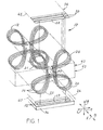
- Fig. 1 illustrates a contactor assembly 10 of the invention which includes a wire 12 that has been wound into a plurality of contactors 14 that lie in a row that extends along a horizontal front-rear F-R, or transverse direction T.
- Each of the contactors has four resilient wire loops 21-24 with loop axes angularly spaced about an axis 26.
- the contactors are useful to connect mating surfaces 28, 29 of two rows of terminals 30, 32 of electronic devices 34, 36.
- device 34 may be a piece of electronic equipment while the device 36 is a circuit board.
- the particular contactor assembly 10 illustrated includes twenty-one contactors. The contactors were originally wound from a single wire, and are electrically separated by cuts at 40 that remove short lengths of the wire.
- the horizontal planes 45, 47 of the two groups of terminals 30, 32 are perpendicular to longitudinal directions M.
- Fig. 3 shows one contactor 14 in the form of wire wound into four loops 21-24.
- Each loop has a transversely-extending axis 44-47.
- Each loop is a closed loop even though the wire does not connect at the loop inner ends 52.
- the location of each axis is at the center of the area of the loop.
- Each loop is symmetric about a line 50 that passes though the axis and though the inner end 52 of the loop.
- Each loop inner end is the end closest to the opposite loop and to the contactor axis 26.
- Each loop extends 360°C about the corresponding axis.
- the upper pair of loops 21, 24 are laterally L spaced, and the lower pair of loops 22, 23 are laterally L spaced.
- the upper and lower loops are vertically, or longitudinally M spaced.
- Fig. 3 the loops lie one behind another in the front-to-rear, or transverse direction T, with loop 21 frontmost, loop 22 lying rearward of loop 21, loop 23 lying rearward of loop 22, and loop 24 lying at the rear of the contactor.
- Fig. 2 shows that the loops lie closely behind one another.
- the contactor lies primarily in a plane, in that the transverse depth A of the four loops of each contactor is less than one half, and preferably less than one-fourth, the longitudinal length or height B of the uncompressed contactors.
- the lateral length (E, Fig. 3 ) of the contactor is more than twice and preferably more than four times its transverse depth A.
- the height B is about eight times the depth A.
- each contactor is closely spaced, so the terminals of the electronic devices can be closely spaced.
- the close spacing allows small electronic devices, such as cell phones, to use the contactors.
- the primarily vertical plane of each contactor is normal to the transverse direction T.
- the contactors are especially useful to fit in a small space and connect miniature terminals.
- the contactor 14 of Fig. 3 had a height B of 2.5 millimeters and the contactors of the row were located at a pitch C ( Fig. 2 ) of about 0.3 millimeter.
- Fig. 3 shows, in phantom lines, the contactor at 14A after it has been depressed by being compressed between the rows of terminals of two electronic devices.
- the contactor has been compressed by a height 2J of about 0.25 millimeters.
- the outer end 60 of each loop moves away from the axis 26 as the loop elongates.
- applicant can form the block 43 of the holder of elastomeric material.
- An elastomeric material is a material that has a Young's modulus of elasticity of no more than 50,000 psi. It is also possible to form the block of a rigid moldable material such as a polymer. If the block is formed of a rigid polymer, it can be formed with grooves, indicated at 64 in Fig. 4 , to receive wire portions near the surfaces of the block that are deflected in the block.
- the use of at least two loops projecting from one of the faces of the block also helps in the manufacture of the contactor assembly.
- the contactors can be cut apart and laid on a surface of a jig, with the two lowermost loops helping to assure proper orientation of the contactors until the holder block is molded around the middles of the contactors.
- Fig. 4 is a front view of a contactor 70 of another embodiment of the invention, shown mounted in an insulative holder 72 in the form of a block.
- the contactor 70 has three loops, including two lower loops 74, 76 and one upper loop 78.
- the upper loop 78 does not provide the degree of stability as two upper loops, but the two lower loops properly orient the contactor during manufacture, so the finished assembly will properly contact upper and lower terminals 80, 82 of the two electronic devices 84, 86.
- the outer ends of the three loops are equally spaced from a transverse axis 90.
- the invention provides a miniature contactor assembly for connecting two rows of terminals, which can be made at low cost and can connect together terminals that are very closely spaced.
- a row of contactors is formed from a single wire that is wound into a set of least three loops for each contactor, with the sets of loops electrically separated by cutting the wound wire or cutting away a length of the wire between each set of loops.
- the loops are held in the proper orientations and at the desired spacing, by a holder block of insulative (e.g. polymer) moldable material.
- a holder block of insulative (e.g. polymer) moldable material Preferably at least two loops project from one of the faces of the holder block, to help orient the contactors during manufacture.
- each contactor has four loops that each has an inner end that is spaced form the axis of the contactor.
Landscapes
- Coupling Device And Connection With Printed Circuit (AREA)
- Connector Housings Or Holding Contact Members (AREA)
Claims (10)
- Ensemble contacteur, comprenant :un fil (12) enroulé en donnant une rangée de contacteurs (14, 70) s'étendant transversalement, chaque contacteur incluant une pluralité de boucles (21, 22, 23, 24, 74, 76, 78) qui s'étendent chacune sur 360° autour d'un axe transversal horizontal (44, 45, 46, 47), les boucles de chaque contacteur étant toutes situées principalement dans le même plan vertical avec leurs axes transversaux parallèles mais écartés, dans lequel ledit fil est coupé (40) entre des contacteurs adjacents pour les isoler électriquement les uns des autres.
- Ensemble contacteur selon la revendication 1, incluant :un support (42) qui comprend un bloc (43) de matériau diélectrique ayant une surface supérieure et une surface inférieure, des portions de chacun desdits contacteurs étant noyées dans le bloc, mais des portions desdites boucles s'étendant au-delà desdites surfaces supérieure et inférieure.
- Ensemble contacteur selon la revendication 2, dans lequel :ledit support (42) est formé en matériau élastomère.
- Ensemble contacteur selon la revendication 2, dans lequel :ledit support (42) est un bloc moulé de matériau polymère rigide qui comporte des gorges (64) permettant à des portions de fil proches de la surface du bloc de se défléchir dans le bloc.
- Ensemble contacteur selon la revendication 1, incluant :des groupes de bornes supérieures et inférieures qui incluent chacun une pluralité de bornes espacées transversalement (30, 32, 80, 82) ;lesdits contacteurs étant disposés verticalement et comprimés entre des bornes desdits groupes de bornes supérieures et inférieures.
- Ensemble contacteur selon l'une des revendications 1 à 5, dans lequel ledit ensemble est utilisé pour connecter électriquement ensemble chacune d'une pluralité de premières bornes (30, 80) espacées transversalement à chacune d'une pluralité de secondes bornes (32, 82) espacées transversalement, dans lesquelles lesdites premières bornes ont des surfaces appariées (28) situées principalement dans un premier plan (45) et lesdites secondes bornes ont des surfaces appariées (29) situées principalement dans un second plan (47) qui est parallèle audit premier plan et espacé de celui-ci, ledit premier et ledit second plan étant chacun normal à une direction longitudinale (M), dans lequel la direction latérale et la direction transversale (L, T) sont perpendiculaires l'une à l'autre et à ladite direction longitudinale.
- Ensemble contacteur selon la revendication 6, dans lequel :ladite première et ladite seconde pluralité de bornes sont situées contre lesdits contacteurs et compriment ces derniers, au moins une première desdites boucles (21, 24, 78) de chacun desdits contacteurs étant située contre chacune desdites premières bornes (30, 80), et au moins une seconde et une troisième (22, 23, 74, 76) desdites boucles de chacun desdits contacteurs étant située sensiblement contre chacune desdites secondes bornes (32, 82).
- Ensemble contacteur selon la revendication 6, dans lequel :ledit fil est cintré pour donner quatre boucles (21, 22, 23, 24) pour chaque contacteur, toutes les boucles d'un contacteur étant situées principalement dans un plan commun, et deux desdites boucles d'un contacteur étant situées adjacentes à l'une desdites premières bornes (36), et deux desdites boucles d'un contacteur étant situées adjacentes à l'une desdites secondes bornes (32).
- Ensemble contacteur selon la revendication 6, dans lequel :ledit support comprend un bloc (43) de matériau polymère ayant une première et une seconde face opposées espacées en sens longitudinal (M), l'une au moins desdites boucles se projetant depuis ladite première face, et au moins deux desdites boucles se projetant depuis ladite seconde face.
- Ensemble contacteur selon la revendication 9, dans lequel :ledit bloc (43) de matériau polymère est en matériau élastomère.
Applications Claiming Priority (1)
| Application Number | Priority Date | Filing Date | Title |
|---|---|---|---|
| US11/818,322 US7384271B1 (en) | 2007-06-14 | 2007-06-14 | Compressive cloverleaf contactor |
Publications (3)
| Publication Number | Publication Date |
|---|---|
| EP2003734A2 EP2003734A2 (fr) | 2008-12-17 |
| EP2003734A3 EP2003734A3 (fr) | 2010-06-23 |
| EP2003734B1 true EP2003734B1 (fr) | 2012-10-17 |
Family
ID=39484312
Family Applications (1)
| Application Number | Title | Priority Date | Filing Date |
|---|---|---|---|
| EP08157136A Not-in-force EP2003734B1 (fr) | 2007-06-14 | 2008-05-29 | Contacteur compressif en feuille de trèfle |
Country Status (4)
| Country | Link |
|---|---|
| US (1) | US7384271B1 (fr) |
| EP (1) | EP2003734B1 (fr) |
| JP (1) | JP4673394B2 (fr) |
| CN (1) | CN101325293B (fr) |
Families Citing this family (4)
| Publication number | Priority date | Publication date | Assignee | Title |
|---|---|---|---|---|
| JP5718203B2 (ja) * | 2011-10-05 | 2015-05-13 | 富士通コンポーネント株式会社 | ソケット用モジュール及びソケット |
| JP2015207433A (ja) * | 2014-04-18 | 2015-11-19 | 矢崎総業株式会社 | 導電性弾性部材及びコネクタ |
| KR102284654B1 (ko) * | 2014-07-02 | 2021-08-03 | 삼성전자 주식회사 | 메모리 카드 |
| AU2018211350B2 (en) * | 2017-08-04 | 2020-02-06 | Preformed Line Products Co. | Helical Jumper Connector |
Family Cites Families (49)
| Publication number | Priority date | Publication date | Assignee | Title |
|---|---|---|---|---|
| US2124462A (en) | 1937-08-18 | 1938-07-19 | Charles R Cummings | Rocket engine |
| US3210722A (en) | 1962-10-29 | 1965-10-05 | Robert H Johns | Helical spring type connector |
| US3783433A (en) | 1971-01-18 | 1974-01-01 | Litton Systems Inc | Solderless electrical connection system |
| JPH0616421Y2 (ja) * | 1988-08-03 | 1994-04-27 | 神明電機株式会社 | コネクタ |
| US5059143A (en) | 1988-09-08 | 1991-10-22 | Amp Incorporated | Connector contact |
| US4973270A (en) | 1989-06-02 | 1990-11-27 | Amp Incorporated | Circuit panel socket with cloverleaf contact |
| US5035628A (en) | 1990-05-29 | 1991-07-30 | Amp Incorporated | Electrical connector for electrically interconnecting two parallel surfaces |
| US5030109A (en) | 1990-08-24 | 1991-07-09 | Amp Incorporated | Area array connector for substrates |
| US5101553A (en) | 1991-04-29 | 1992-04-07 | Microelectronics And Computer Technology Corporation | Method of making a metal-on-elastomer pressure contact connector |
| US5273438A (en) * | 1992-08-19 | 1993-12-28 | The Whitaker Corporation | Canted coil spring array and method for producing the same |
| JP2863048B2 (ja) * | 1992-09-18 | 1999-03-03 | エスエムケイ株式会社 | 多極コネクタプラグ |
| JP2590790Y2 (ja) * | 1992-09-18 | 1999-02-17 | エスエムケイ株式会社 | コネクタ用コンタクトの構造 |
| US5360347A (en) * | 1993-06-17 | 1994-11-01 | The Whitaker Corporation | Laminated surface mount interconnection system |
| JP2655802B2 (ja) * | 1993-06-30 | 1997-09-24 | 山一電機株式会社 | コイル形接触子及びこれを用いたコネクタ |
| US5397240A (en) | 1993-10-26 | 1995-03-14 | International Business Machines Corporation | Electrical connector |
| JPH07230863A (ja) * | 1994-02-09 | 1995-08-29 | Whitaker Corp:The | 基板用コネクタ及び基板接続方法 |
| US5636996A (en) * | 1994-06-28 | 1997-06-10 | The Whitaker Corporation | Anisotropic interposer pad |
| US5540594A (en) * | 1994-06-29 | 1996-07-30 | The Whitaker Corporation | Elastomeric connector having increased compression range |
| DE19605661A1 (de) * | 1995-02-24 | 1996-08-29 | Whitaker Corp | Elektrisches Verbinderbauteil zur Herstellung einer elektrischen Verbindung zwischen leitfähigen Flächen |
| US5588846A (en) * | 1995-08-25 | 1996-12-31 | The Whitaker Corporation | Right angle electrical connector |
| US5573435A (en) | 1995-08-31 | 1996-11-12 | The Whitaker Corporation | Tandem loop contact for an electrical connector |
| US5632626A (en) * | 1996-01-05 | 1997-05-27 | The Whitaker Corporation | Retention of elastomeric connector in a housing |
| US6222126B1 (en) * | 1997-09-08 | 2001-04-24 | Thomas & Betts International, Inc. | Woven mesh interconnect |
| US5973394A (en) | 1998-01-23 | 1999-10-26 | Kinetrix, Inc. | Small contactor for test probes, chip packaging and the like |
| JP2000268901A (ja) * | 1999-03-18 | 2000-09-29 | Yokowo Co Ltd | コイルばねコンタクト式コネクタ |
| US6313523B1 (en) | 1999-10-28 | 2001-11-06 | Hewlett-Packard Company | IC die power connection using canted coil spring |
| DE19963406A1 (de) | 1999-12-28 | 2001-07-12 | Nokia Mobile Phones Ltd | Kontaktelement |
| US6328573B1 (en) * | 2000-02-29 | 2001-12-11 | Hirose Electric Co., Ltd. | Intermediate electrical connector |
| JP3977009B2 (ja) * | 2000-03-24 | 2007-09-19 | 株式会社ヨコオ | コイルばねコンタクト式コネクタ |
| US6439894B1 (en) * | 2001-01-31 | 2002-08-27 | High Connection Density, Inc. | Contact assembly for land grid array interposer or electrical connector |
| CN2518236Y (zh) * | 2001-11-27 | 2002-10-23 | 鸿松精密科技股份有限公司 | 具有整体式端子的连接器 |
| US6551112B1 (en) | 2002-03-18 | 2003-04-22 | High Connection Density, Inc. | Test and burn-in connector |
| TW551630U (en) | 2002-06-28 | 2003-09-01 | Hon Hai Prec Ind Co Ltd | Contact |
| US6877992B2 (en) | 2002-11-01 | 2005-04-12 | Airborn, Inc. | Area array connector having stacked contacts for improved current carrying capacity |
| US20040132320A1 (en) * | 2002-12-20 | 2004-07-08 | Dittmann Larry E. | Land grid array connector |
| JP3832828B2 (ja) * | 2003-03-20 | 2006-10-11 | 日本航空電子工業株式会社 | コネクタ |
| US7040902B2 (en) * | 2003-03-24 | 2006-05-09 | Che-Yu Li & Company, Llc | Electrical contact |
| US7014479B2 (en) * | 2003-03-24 | 2006-03-21 | Che-Yu Li | Electrical contact and connector and method of manufacture |
| US20060172564A1 (en) * | 2003-07-07 | 2006-08-03 | Mattias Nilsson | Testing of interconnections between stacked circuit boards |
| CN2669399Y (zh) * | 2003-07-31 | 2005-01-05 | 汪应斌 | 一种电连接器及一种电路板 |
| JP4288130B2 (ja) * | 2003-09-30 | 2009-07-01 | 東京エレクトロン株式会社 | 電気的接合部材及びプラズマ処理装置 |
| US7074096B2 (en) | 2003-10-30 | 2006-07-11 | Tyco Electronics Corporation | Electrical contact with plural arch-shaped elements |
| US6958616B1 (en) * | 2003-11-07 | 2005-10-25 | Xilinx, Inc. | Hybrid interface apparatus for testing integrated circuits having both low-speed and high-speed input/output pins |
| US6981879B2 (en) * | 2004-03-18 | 2006-01-03 | International Business Machines Corporation | Land grid array (LGA) interposer with adhesive-retained contacts and method of manufacture |
| FR2870382A1 (fr) * | 2004-05-13 | 2005-11-18 | Commissariat Energie Atomique | Cablage de connexion elastique |
| US6981880B1 (en) * | 2004-06-22 | 2006-01-03 | International Business Machines Corporation | Non-oriented wire in elastomer electrical contact |
| JP2006140008A (ja) * | 2004-11-11 | 2006-06-01 | Micro Hatsujo:Kk | 電気接点及びその繰返し構造体、並びに、該電気接点を用いた電子機器 |
| US7255572B2 (en) * | 2005-08-31 | 2007-08-14 | Yokowo Co., Ltd. | Electrical connector provided with coiled spring contact |
| US7338294B2 (en) * | 2006-06-28 | 2008-03-04 | Hon Hai Precision Ind. Co., Ltd. | Pressure contact connector |
-
2007
- 2007-06-14 US US11/818,322 patent/US7384271B1/en active Active
-
2008
- 2008-05-13 CN CN2008100995315A patent/CN101325293B/zh not_active Expired - Fee Related
- 2008-05-29 EP EP08157136A patent/EP2003734B1/fr not_active Not-in-force
- 2008-06-16 JP JP2008156780A patent/JP4673394B2/ja not_active Expired - Fee Related
Also Published As
| Publication number | Publication date |
|---|---|
| EP2003734A2 (fr) | 2008-12-17 |
| EP2003734A3 (fr) | 2010-06-23 |
| US7384271B1 (en) | 2008-06-10 |
| CN101325293A (zh) | 2008-12-17 |
| JP4673394B2 (ja) | 2011-04-20 |
| CN101325293B (zh) | 2011-01-26 |
| JP2008311230A (ja) | 2008-12-25 |
Similar Documents
| Publication | Publication Date | Title |
|---|---|---|
| AU2003272469B8 (en) | Electrical connector jack | |
| US8858238B2 (en) | Compression connector configured with three housing for retaining terminals there between | |
| CN112086780B (zh) | 夹层式电连接器 | |
| EP1891664B1 (fr) | Connecteur electrique a structure portante | |
| EP1897177B1 (fr) | Element d'alignement du logement d'un connecteur electrique | |
| US9203172B2 (en) | Electrical connector assembly and electrical connector used therefor | |
| US5997315A (en) | Connector and IC card connector | |
| US7597593B2 (en) | Leadframe assembly staggering for electrical connectors | |
| CA1227255A (fr) | Connecteur lateral pour support de puce | |
| US6805561B1 (en) | Electrical socket having terminals with elongated mating beams | |
| US8696389B2 (en) | Card edge connector | |
| US20110250800A1 (en) | Board to board connector assembly having improved plug and receptacle contacts | |
| JP2011134582A (ja) | 平型ケーブル用コネクタ、その製造方法及びロック機構 | |
| US8172623B1 (en) | Compression connector having contacting ends with co-used deforming section | |
| EP1128477A2 (fr) | Connecteur électrique avec contacts à compression | |
| CN104253337A (zh) | 连接器以及在该连接器中使用的插头件及插口件 | |
| EP2003734B1 (fr) | Contacteur compressif en feuille de trèfle | |
| CN104253325A (zh) | 连接器以及在该连接器中使用的插头件及插口件 | |
| US20060246746A1 (en) | Electrical connector with improved terminal | |
| US20160197427A1 (en) | Battery connector and manufacturing method therefor | |
| US7462037B2 (en) | Electrical connector | |
| US6840809B2 (en) | Electrical connector having improved contacts | |
| US10505299B2 (en) | Electrical connector having an improved metal shell with a soldering portion | |
| US6832936B2 (en) | Terminal module for electrical connector | |
| US9853385B1 (en) | Axial compliant compression electrical connector |
Legal Events
| Date | Code | Title | Description |
|---|---|---|---|
| PUAI | Public reference made under article 153(3) epc to a published international application that has entered the european phase |
Free format text: ORIGINAL CODE: 0009012 |
|
| 17P | Request for examination filed |
Effective date: 20080529 |
|
| AK | Designated contracting states |
Kind code of ref document: A2 Designated state(s): AT BE BG CH CY CZ DE DK EE ES FI FR GB GR HR HU IE IS IT LI LT LU LV MC MT NL NO PL PT RO SE SI SK TR |
|
| AX | Request for extension of the european patent |
Extension state: AL BA MK RS |
|
| PUAL | Search report despatched |
Free format text: ORIGINAL CODE: 0009013 |
|
| AK | Designated contracting states |
Kind code of ref document: A3 Designated state(s): AT BE BG CH CY CZ DE DK EE ES FI FR GB GR HR HU IE IS IT LI LT LU LV MC MT NL NO PL PT RO SE SI SK TR |
|
| AX | Request for extension of the european patent |
Extension state: AL BA MK RS |
|
| 17Q | First examination report despatched |
Effective date: 20100722 |
|
| AKX | Designation fees paid |
Designated state(s): DE FR GB |
|
| REG | Reference to a national code |
Ref country code: DE Ref legal event code: R079 Ref document number: 602008019396 Country of ref document: DE Free format text: PREVIOUS MAIN CLASS: H01R0004480000 Ipc: H01R0012710000 |
|
| RIC1 | Information provided on ipc code assigned before grant |
Ipc: H01R 12/71 20110101AFI20120322BHEP |
|
| GRAP | Despatch of communication of intention to grant a patent |
Free format text: ORIGINAL CODE: EPIDOSNIGR1 |
|
| GRAS | Grant fee paid |
Free format text: ORIGINAL CODE: EPIDOSNIGR3 |
|
| GRAA | (expected) grant |
Free format text: ORIGINAL CODE: 0009210 |
|
| AK | Designated contracting states |
Kind code of ref document: B1 Designated state(s): DE FR GB |
|
| RAP1 | Party data changed (applicant data changed or rights of an application transferred) |
Owner name: ITT MANUFACTURING ENTERPRISES LLC |
|
| REG | Reference to a national code |
Ref country code: GB Ref legal event code: FG4D |
|
| REG | Reference to a national code |
Ref country code: DE Ref legal event code: R096 Ref document number: 602008019396 Country of ref document: DE Effective date: 20121213 |
|
| PLBE | No opposition filed within time limit |
Free format text: ORIGINAL CODE: 0009261 |
|
| STAA | Information on the status of an ep patent application or granted ep patent |
Free format text: STATUS: NO OPPOSITION FILED WITHIN TIME LIMIT |
|
| 26N | No opposition filed |
Effective date: 20130718 |
|
| REG | Reference to a national code |
Ref country code: DE Ref legal event code: R097 Ref document number: 602008019396 Country of ref document: DE Effective date: 20130718 |
|
| REG | Reference to a national code |
Ref country code: FR Ref legal event code: PLFP Year of fee payment: 8 |
|
| PGFP | Annual fee paid to national office [announced via postgrant information from national office to epo] |
Ref country code: GB Payment date: 20150527 Year of fee payment: 8 Ref country code: DE Payment date: 20150528 Year of fee payment: 8 |
|
| PGFP | Annual fee paid to national office [announced via postgrant information from national office to epo] |
Ref country code: FR Payment date: 20150519 Year of fee payment: 8 |
|
| REG | Reference to a national code |
Ref country code: DE Ref legal event code: R119 Ref document number: 602008019396 Country of ref document: DE |
|
| GBPC | Gb: european patent ceased through non-payment of renewal fee |
Effective date: 20160529 |
|
| REG | Reference to a national code |
Ref country code: FR Ref legal event code: ST Effective date: 20170131 |
|
| PG25 | Lapsed in a contracting state [announced via postgrant information from national office to epo] |
Ref country code: FR Free format text: LAPSE BECAUSE OF NON-PAYMENT OF DUE FEES Effective date: 20160531 Ref country code: DE Free format text: LAPSE BECAUSE OF NON-PAYMENT OF DUE FEES Effective date: 20161201 |
|
| PG25 | Lapsed in a contracting state [announced via postgrant information from national office to epo] |
Ref country code: GB Free format text: LAPSE BECAUSE OF NON-PAYMENT OF DUE FEES Effective date: 20160529 |