EP2006030A2 - Dispositif destiné à l'application de matières pouvant s'écouler - Google Patents
Dispositif destiné à l'application de matières pouvant s'écouler Download PDFInfo
- Publication number
- EP2006030A2 EP2006030A2 EP08155863A EP08155863A EP2006030A2 EP 2006030 A2 EP2006030 A2 EP 2006030A2 EP 08155863 A EP08155863 A EP 08155863A EP 08155863 A EP08155863 A EP 08155863A EP 2006030 A2 EP2006030 A2 EP 2006030A2
- Authority
- EP
- European Patent Office
- Prior art keywords
- outer closure
- outlet opening
- metering valve
- rest position
- holder
- Prior art date
- Legal status (The legal status is an assumption and is not a legal conclusion. Google has not performed a legal analysis and makes no representation as to the accuracy of the status listed.)
- Withdrawn
Links
- 239000000126 substance Substances 0.000 title claims abstract description 10
- 230000009969 flowable effect Effects 0.000 claims abstract description 14
- 239000000853 adhesive Substances 0.000 claims abstract description 3
- 230000001070 adhesive effect Effects 0.000 claims abstract description 3
- 238000004140 cleaning Methods 0.000 claims description 22
- 238000007789 sealing Methods 0.000 claims description 13
- 239000000463 material Substances 0.000 claims description 9
- 125000006850 spacer group Chemical group 0.000 claims description 7
- 238000006073 displacement reaction Methods 0.000 claims description 4
- 239000012815 thermoplastic material Substances 0.000 claims description 3
- 239000013013 elastic material Substances 0.000 claims description 2
- 239000003973 paint Substances 0.000 claims description 2
- 239000002966 varnish Substances 0.000 claims description 2
- 230000000284 resting effect Effects 0.000 abstract 2
- 238000001035 drying Methods 0.000 description 2
- 230000000694 effects Effects 0.000 description 2
- 239000003292 glue Substances 0.000 description 2
- 238000005299 abrasion Methods 0.000 description 1
- 238000001514 detection method Methods 0.000 description 1
- 239000012535 impurity Substances 0.000 description 1
- 238000012423 maintenance Methods 0.000 description 1
- 238000004519 manufacturing process Methods 0.000 description 1
- 230000002265 prevention Effects 0.000 description 1
- 238000009420 retrofitting Methods 0.000 description 1
- 238000010408 sweeping Methods 0.000 description 1
Images


Classifications
-
- B—PERFORMING OPERATIONS; TRANSPORTING
- B05—SPRAYING OR ATOMISING IN GENERAL; APPLYING FLUENT MATERIALS TO SURFACES, IN GENERAL
- B05C—APPARATUS FOR APPLYING FLUENT MATERIALS TO SURFACES, IN GENERAL
- B05C5/00—Apparatus in which liquid or other fluent material is projected, poured or allowed to flow on to the surface of the work
- B05C5/02—Apparatus in which liquid or other fluent material is projected, poured or allowed to flow on to the surface of the work the liquid or other fluent material being discharged through an outlet orifice by pressure, e.g. from an outlet device in contact or almost in contact, with the work
-
- B—PERFORMING OPERATIONS; TRANSPORTING
- B05—SPRAYING OR ATOMISING IN GENERAL; APPLYING FLUENT MATERIALS TO SURFACES, IN GENERAL
- B05B—SPRAYING APPARATUS; ATOMISING APPARATUS; NOZZLES
- B05B15/00—Details of spraying plant or spraying apparatus not otherwise provided for; Accessories
- B05B15/50—Arrangements for cleaning; Arrangements for preventing deposits, drying-out or blockage; Arrangements for detecting improper discharge caused by the presence of foreign matter
- B05B15/52—Arrangements for cleaning; Arrangements for preventing deposits, drying-out or blockage; Arrangements for detecting improper discharge caused by the presence of foreign matter for removal of clogging particles
Definitions
- the invention relates to a device for applying flowable substances, in particular adhesives, paints or varnishes, to a carrier, to a dosing valve connected to the carrier, which comprises an outlet opening for the flowable substance, and to an outer closure for the outlet opening of the dosing valve.
- Such a device is known from DE 199 36 670 C1 known.
- the metering valve is movably disposed on a fixed support between a working position and a rest position, wherein in the rest position, the outer closure closes the outlet opening from the outside.
- the invention is therefore the object of developing a generic device such that their space requirement is reduced.
- the metering valve is arranged such that its outlet opening is directed upward, and that the outer closure for the outlet opening between a working position and a rest position is movably disposed, wherein in the rest position, the outer closure closes the outlet opening from the outside, operates in the inventive Set up the dosing valve from bottom to top and fixed.
- the outer closure is pivoted above the valve. Due to the rigid arrangement of the metering valves, these can be accommodated where there is regularly not enough space for pivoting, namely in the device below the product to which the flowable material must be applied. The device thus builds considerably more compact than the cited in the prior art, since no operating and / or supply lines and support members must be placed above the product.
- the device according to the invention may be arranged over the product substantially the outer closure with actuating means for effecting the pivoting movement. Furthermore, the device according to the invention has the advantage that the outer closure above the product for maintenance purposes is easily accessible and visible, so that the handling of the device according to the invention over the prior art is improved.
- the outer closure is attached to a holder, which is arranged pivotably about an axis on a fixed support.
- a holder which is arranged pivotably about an axis on a fixed support.
- Such an arrangement can be formed easily and with high stability. It is also suitable for retrofitting existing systems.
- the rotary actuator can be configured in various ways.
- it may have a variable-length element, which may be a piston / cylinder arrangement.
- the pivot drive in a further preferred embodiment may also include a rotary motor.
- the outer closure contains a cleaning area.
- This cleaning area is arranged so that it cleans the outlet opening during the sweeping movement of the metering valve between the working position and the rest position from there possibly adhering residues. It is advantageous that the cleaning area can be specially designed and optimized for the cleaning task, so that it fulfills its function without polluting for a long time.
- the cleaning area comprises a corrugated surface.
- a corrugated surface Such a design effectively leads to detachment of adhering residues of the flowable substance to be applied. Detached residues can accumulate in the depressions without completely covering the actual cleaning surface, which would lead to a reduction or even prevention of the cleaning effect.
- the cleaning area may preferably be made of a low-abrasion, hard material, which, however, does not cause any functionally significant closure at the metering valve by recoating.
- a hard, rubber-elastic material or a thermoplastic material into consideration.
- the outer closure preferably further comprises a sealing region, which is arranged so that it seals the outlet opening of the metering valve in the rest position of the outer closure.
- the sealing area thus ensures that no flowable material can escape from the device when it is not in use.
- the closing of the outlet opening is preferably gas-tight, so that the access of air into the interior of the metering valve is prevented and drying of the substance located there is prevented.
- This sealing region is preferably made of a material which is soft with respect to that of the cleaning region, in particular of softer rubber or softer thermoplastic material. by virtue of the use of the softer material, the outlet can be effectively closed at a sufficient contact pressure to compensate for unevenness.
- the outer closure is - particularly preferably - elastically mounted on the holder. Due to this measure tolerances are compensated automatically, for example, in the distance between the outlet opening and the outer closure, provided that the change in distance moves in a range that can be compensated by the elastic bearing.
- the holder for the outer closure comprises at least one spacer protruding toward the metering valve in the rest position which interacts with the metering valve when moving the outer closure from the working to the rest position and determines the position of the outer closure and the nozzle relative to each other.
- the handling of the device according to the invention is considerably simplified, since due to the spacer, a fine adjustment of the distance between the nozzle and the outer closure is not required. Because the spacer ensures that the distance between the outer closure and the nozzle is always the same even with certain manufacturing tolerances. In this way - if a cleaning area is provided - an optimal cleaning, but always an optimal sealing result achieved, while low wear of the outer closure and the nozzle.
- the device according to the invention which comprises sensor elements for detecting objects in the swivel range of the outer closure and a device control connected to the sensor elements, which prevents a displacement of the outer closure in the rest position for objects in the swivel range.
- sensor elements which may be formed for example as a light scanner, check the presence of a product in the swivel range of the outer closure.
- the device control is programmed so that when detecting a product, the outer closure is locked in its working position.
- the device control is programmed so that it shuts down the feed device when switching off the device only when the Product has been led out of the swivel range. Due to this measure, it is ensured that a collision between the outer closure and the product can not occur. Furthermore, it can be provided in such a device that when switching off the device, the outer closure is always displaced to its rest position, so that the outlet opening never remains open when the device is stationary.
- the device control may preferably be programmed such that the feed device only activates the feed device when the device is switched on when the outer closure has been displaced into its working position. Due to this measure, it is ensured that it can not come to a collision of the product with the outer closure when starting the device, whereby product scrap and possible damage to the outer closure and the metering valve can be prevented.
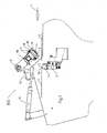
- a flowable material such as glue on a leading in the direction of arrow P product 1. It includes a metering valve 2, which is disposed below the product 1 to a holder 11. It comprises a glue outlet opening 3, which is formed by a nozzle 3a. By means of the metering valve 2, the flowable substance is applied to the product 1 from below.
- an outer closure 8 is arranged above the metering valve 2, above the metering valve 2, an outer closure 8 is arranged. He is on a support 13 about a pivot axis S between a in Fig. 1 work position shown and one in Fig. 2 illustrated rest position by means of a hinged to the outer closure 8Centralnverstellers 7.
- the outer closure 8 is mounted on a holder 8 a and comprises an element 4 made of rubber materials, which comprises a sealing region 5 and a cleaning region 6. Sealing area 5 and cleaning area 6 are arranged such that at a shift from the in Fig. 1 shown working position in a Fig. 2 illustrated rest position of the cleaning area 6 the sealing area 5 leads.
- the outer closure 8 comprises a spacer 10, which projects beyond the element 4 by approximately the same amount that the outlet opening 3 projects beyond the holder 11.
- the outer closure 8 also elastic Elements 9 is mounted by the holder 8 a, which are arranged such that the element 4 when passing over the nozzle 3 a relative to the carrier 13, overcoming the elastic force caused by the elastic elements 9 is displaceable, and the spacers 10 are designed such that they sweep the holder 11 like a runner when moving the outer closure from the working to the rest position, automatically sets the optimal distance between the element 4 and the holder 11 for optimum cleaning and sealing action of the outer closure.
- FIG. 3 further embodiment of the device 200 according to the invention differs from that with reference to FIG Fig. 1 and 2 described only in that sensor elements 12 are provided which detect the presence of objects, in particular of product 1 in the pivoting range of the outer closure 8.
- the sensor elements 12 are connected to a device control, not shown in the drawing, that in the detection of objects, a displacement of the outer closure 8 from his in Fig. 3 shown work position is blocked in the rest position.
- the device control is programmed so that in the event that the device is stopped, a displacement of the outer closure from the working to the rest position takes place only when the sensor elements 12 detect any object in the pivoting range.
Landscapes
- Coating Apparatus (AREA)
Applications Claiming Priority (1)
| Application Number | Priority Date | Filing Date | Title |
|---|---|---|---|
| DE202007008822U DE202007008822U1 (de) | 2007-06-21 | 2007-06-21 | Vorrichtung zum Auftragen von fließfähigen Stoffen |
Publications (2)
| Publication Number | Publication Date |
|---|---|
| EP2006030A2 true EP2006030A2 (fr) | 2008-12-24 |
| EP2006030A3 EP2006030A3 (fr) | 2012-01-04 |
Family
ID=38460842
Family Applications (1)
| Application Number | Title | Priority Date | Filing Date |
|---|---|---|---|
| EP08155863A Withdrawn EP2006030A3 (fr) | 2007-06-21 | 2008-05-08 | Dispositif destiné à l'application de matières pouvant s'écouler |
Country Status (2)
| Country | Link |
|---|---|
| EP (1) | EP2006030A3 (fr) |
| DE (1) | DE202007008822U1 (fr) |
Cited By (3)
| Publication number | Priority date | Publication date | Assignee | Title |
|---|---|---|---|---|
| EP2835180A1 (fr) * | 2013-08-06 | 2015-02-11 | Robatech AG | Dispositif de distribution de produits fluides |
| EP2835181A1 (fr) * | 2013-08-06 | 2015-02-11 | Robatech AG | Dispositif de distribution de produits fluides |
| EP2878382A1 (fr) | 2013-11-29 | 2015-06-03 | Müller Martini Holding AG | Procédé et dispositif d'application d'un produit coulant |
Families Citing this family (2)
| Publication number | Priority date | Publication date | Assignee | Title |
|---|---|---|---|---|
| DE102016000064A1 (de) | 2016-01-06 | 2017-07-06 | Baumer Hhs Gmbh | Klebstoffauftragsvorrichtung |
| DE102016007417A1 (de) * | 2016-06-20 | 2017-12-21 | Focke & Co. (Gmbh & Co. Kg) | Station zum Aufbringen von fluiden Medien auf ein Substrat und Verfahren zum Betreiben derselben |
Citations (1)
| Publication number | Priority date | Publication date | Assignee | Title |
|---|---|---|---|---|
| DE19936670C1 (de) | 1999-08-04 | 2001-02-08 | Hhs Leimauftrags Systeme Gmbh | Vorrichtung zum Auftragen von fließfähigen Stoffen |
Family Cites Families (3)
| Publication number | Priority date | Publication date | Assignee | Title |
|---|---|---|---|---|
| DE19540655B4 (de) * | 1995-10-31 | 2005-11-17 | Planatol Klebetechnik Gmbh | Leim-Auftragsvorrichtung |
| DE29809483U1 (de) * | 1998-05-28 | 1999-10-21 | Nordson Corp., Westlake, Ohio | Vorrichtung zum wahlweisen Schließen einer Öffnung sowie Auftragskopf |
| JP2005013837A (ja) * | 2003-06-25 | 2005-01-20 | Mitsubishi Heavy Ind Ltd | 塗工装置用スリットノズルのクリーニング装置及び塗工装置 |
-
2007
- 2007-06-21 DE DE202007008822U patent/DE202007008822U1/de not_active Expired - Lifetime
-
2008
- 2008-05-08 EP EP08155863A patent/EP2006030A3/fr not_active Withdrawn
Patent Citations (1)
| Publication number | Priority date | Publication date | Assignee | Title |
|---|---|---|---|---|
| DE19936670C1 (de) | 1999-08-04 | 2001-02-08 | Hhs Leimauftrags Systeme Gmbh | Vorrichtung zum Auftragen von fließfähigen Stoffen |
Cited By (6)
| Publication number | Priority date | Publication date | Assignee | Title |
|---|---|---|---|---|
| EP2835180A1 (fr) * | 2013-08-06 | 2015-02-11 | Robatech AG | Dispositif de distribution de produits fluides |
| EP2835181A1 (fr) * | 2013-08-06 | 2015-02-11 | Robatech AG | Dispositif de distribution de produits fluides |
| US9394097B2 (en) | 2013-08-06 | 2016-07-19 | Robatech Ag | Apparatus for dispensing flowable substances |
| US9487341B2 (en) | 2013-08-06 | 2016-11-08 | Robatech Ag | Apparatus for dispensing flowable substances |
| EP2878382A1 (fr) | 2013-11-29 | 2015-06-03 | Müller Martini Holding AG | Procédé et dispositif d'application d'un produit coulant |
| US10183307B2 (en) | 2013-11-29 | 2019-01-22 | Mueller Martini Holding Ag | Method for applying a flowable substance |
Also Published As
| Publication number | Publication date |
|---|---|
| EP2006030A3 (fr) | 2012-01-04 |
| DE202007008822U1 (de) | 2007-08-30 |
Similar Documents
| Publication | Publication Date | Title |
|---|---|---|
| DE202011000179U1 (de) | Membranaufhängung zur Verwendung in einem Klebstoff-Auftragskopf und Klebstoff-Auftragskopf mit Membranaufhängung | |
| EP2006030A2 (fr) | Dispositif destiné à l'application de matières pouvant s'écouler | |
| DE10024407C2 (de) | Vorrichtung zur Beschichtung von Granulaten und Kernen | |
| WO2012100844A1 (fr) | Suspension à bras de levier pour une tête d'application | |
| DE102014012595A1 (de) | Vorrichtung zum Behandeln von Gegenständen | |
| EP1842599A2 (fr) | Procédé et dispositif destinés au nettoyage d'au moins une unité d'application comportant une ouverture de sortie de fluide pour l'application d'un fluide | |
| WO2009003924A1 (fr) | Dispositif pour étancher un espace fermé | |
| EP3057844B1 (fr) | Dispositif de dosage de granulés | |
| EP0680897A1 (fr) | Dispositif de vidage pour conteneurs pour matériaux en vrac | |
| DE102009019192B4 (de) | Kurzraupenpistole | |
| AT394169B (de) | Streugeraet | |
| DE3908453A1 (de) | Verfahren und vorrichtung zum diskontinuierlichen ausbringen von an der luft erstarrenden applikationsfluessigkeiten aus auftragsduesen | |
| EP3524488A1 (fr) | Dispositif de déchargement permettant de régler la largeur intérieure d'une ouverture de décharge d'un silo de transport de marchandises en vrac conçu pour décharger par gravité à l'aide dudit dispositif de déchargement | |
| DE102009021782A1 (de) | Beschichtungsvorrichtung für langgestreckte Werkstücke | |
| EP2248598B2 (fr) | Dispositif doté de plusieurs buses d'air sec et procédé de distribution de colle | |
| DE19936670C1 (de) | Vorrichtung zum Auftragen von fließfähigen Stoffen | |
| EP2248599B1 (fr) | Dispositif doté de plusieurs buses d'air sec et de chambres de protection ainsi que procédé de distribution de colle | |
| DE102012010617A1 (de) | Verschlusseinrichtung für Druckköpfe | |
| EP3983190A1 (fr) | Dispositif pour la préparation et le traitement d'un mélange à plusieurs composants et procédé pour faire fonctionner un tel dispositif | |
| EP2301678A1 (fr) | Dispositif doté d'un agencement de buses en forme de poutre et procédé de dépôt d'une matière adhésive | |
| DE20015168U1 (de) | Messerhalter mit Stoßabsorber für eine Einrichtung zum Längsteilen einer Materialbahn | |
| DE102022130446A1 (de) | Vorrichtung und Verfahren zum Beschichten eines Werkstücks | |
| DE10139815A1 (de) | Membranventil | |
| DE102016221066B4 (de) | Vorrichtung zur Herstellung einer Kautschukmischung | |
| DE102012009661A1 (de) | Pneumatikventil für eine Textilmaschine |
Legal Events
| Date | Code | Title | Description |
|---|---|---|---|
| PUAI | Public reference made under article 153(3) epc to a published international application that has entered the european phase |
Free format text: ORIGINAL CODE: 0009012 |
|
| AK | Designated contracting states |
Kind code of ref document: A2 Designated state(s): AT BE BG CH CY CZ DE DK EE ES FI FR GB GR HR HU IE IS IT LI LT LU LV MC MT NL NO PL PT RO SE SI SK TR |
|
| AX | Request for extension of the european patent |
Extension state: AL BA MK RS |
|
| PUAL | Search report despatched |
Free format text: ORIGINAL CODE: 0009013 |
|
| AK | Designated contracting states |
Kind code of ref document: A3 Designated state(s): AT BE BG CH CY CZ DE DK EE ES FI FR GB GR HR HU IE IS IT LI LT LU LV MC MT NL NO PL PT RO SE SI SK TR |
|
| AX | Request for extension of the european patent |
Extension state: AL BA MK RS |
|
| RIC1 | Information provided on ipc code assigned before grant |
Ipc: B05C 5/02 20060101ALI20111201BHEP Ipc: B05B 15/02 20060101AFI20111201BHEP |
|
| STAA | Information on the status of an ep patent application or granted ep patent |
Free format text: STATUS: THE APPLICATION IS DEEMED TO BE WITHDRAWN |
|
| 18D | Application deemed to be withdrawn |
Effective date: 20111201 |