EP2006455A1 - Schalungsträger - Google Patents
Schalungsträger Download PDFInfo
- Publication number
- EP2006455A1 EP2006455A1 EP08158068A EP08158068A EP2006455A1 EP 2006455 A1 EP2006455 A1 EP 2006455A1 EP 08158068 A EP08158068 A EP 08158068A EP 08158068 A EP08158068 A EP 08158068A EP 2006455 A1 EP2006455 A1 EP 2006455A1
- Authority
- EP
- European Patent Office
- Prior art keywords
- support
- section
- support section
- tie
- cavity
- Prior art date
- Legal status (The legal status is an assumption and is not a legal conclusion. Google has not performed a legal analysis and makes no representation as to the accuracy of the status listed.)
- Withdrawn
Links
- 238000009416 shuttering Methods 0.000 title description 3
- 239000000463 material Substances 0.000 claims abstract description 31
- 238000010276 construction Methods 0.000 claims abstract description 6
- 230000015572 biosynthetic process Effects 0.000 claims abstract description 5
- 238000000465 moulding Methods 0.000 claims description 19
- XLYOFNOQVPJJNP-UHFFFAOYSA-N water Substances O XLYOFNOQVPJJNP-UHFFFAOYSA-N 0.000 claims description 11
- 238000009414 blockwork Methods 0.000 description 6
- 239000011449 brick Substances 0.000 description 4
- 229910001220 stainless steel Inorganic materials 0.000 description 4
- 239000010935 stainless steel Substances 0.000 description 4
- UQMRAFJOBWOFNS-UHFFFAOYSA-N butyl 2-(2,4-dichlorophenoxy)acetate Chemical compound CCCCOC(=O)COC1=CC=C(Cl)C=C1Cl UQMRAFJOBWOFNS-UHFFFAOYSA-N 0.000 description 3
- 238000005755 formation reaction Methods 0.000 description 3
- 239000002184 metal Substances 0.000 description 3
- 229910052751 metal Inorganic materials 0.000 description 3
- 230000000694 effects Effects 0.000 description 2
- 238000009415 formwork Methods 0.000 description 2
- 238000004519 manufacturing process Methods 0.000 description 2
- 229910000831 Steel Inorganic materials 0.000 description 1
- 238000001125 extrusion Methods 0.000 description 1
- 238000011065 in-situ storage Methods 0.000 description 1
- 238000007373 indentation Methods 0.000 description 1
- 239000007769 metal material Substances 0.000 description 1
- 150000002739 metals Chemical class 0.000 description 1
- 238000000034 method Methods 0.000 description 1
- 230000002265 prevention Effects 0.000 description 1
- 230000003014 reinforcing effect Effects 0.000 description 1
- 239000012779 reinforcing material Substances 0.000 description 1
- 239000010959 steel Substances 0.000 description 1
- 239000011800 void material Substances 0.000 description 1
- 239000002023 wood Substances 0.000 description 1
Images


Classifications
-
- E—FIXED CONSTRUCTIONS
- E02—HYDRAULIC ENGINEERING; FOUNDATIONS; SOIL SHIFTING
- E02D—FOUNDATIONS; EXCAVATIONS; EMBANKMENTS; UNDERGROUND OR UNDERWATER STRUCTURES
- E02D27/00—Foundations as substructures
- E02D27/01—Flat foundations
-
- E—FIXED CONSTRUCTIONS
- E02—HYDRAULIC ENGINEERING; FOUNDATIONS; SOIL SHIFTING
- E02D—FOUNDATIONS; EXCAVATIONS; EMBANKMENTS; UNDERGROUND OR UNDERWATER STRUCTURES
- E02D27/00—Foundations as substructures
- E02D27/01—Flat foundations
- E02D27/02—Flat foundations without substantial excavation
-
- E—FIXED CONSTRUCTIONS
- E02—HYDRAULIC ENGINEERING; FOUNDATIONS; SOIL SHIFTING
- E02D—FOUNDATIONS; EXCAVATIONS; EMBANKMENTS; UNDERGROUND OR UNDERWATER STRUCTURES
- E02D27/00—Foundations as substructures
- E02D27/01—Flat foundations
- E02D27/08—Reinforcements for flat foundations
Definitions
- This invention relates to a system for supporting concrete or other settable material during the construction of a foundation raft or other low level beams.
- a building or other superstructure When building on ground which is liable to subsidence or heave, it is well known to erect a building or other superstructure on a raft or beam, itself supported by piles.
- the underside of the raft may be spaced above the ground by a void or compressible material.
- the raft or beam is typically cast in situ and it typically formed by pouring concrete or other settable material into formwork which defines the desired shape of the beam or raft.
- this formwork takes the form of temporary shuttering, usually formed from wood or a metal such as stainless steel.
- the shuttering is removed and a separate support angle is provided around the edge of the raft or beam such that the appropriate wall or other blockwork can be built upon the support angle.
- the present invention aims to provide a support arrangement which overcomes the problems described above and which improves on the arrangements disclosed in our earlier publications.
- a system for supporting concrete or other settable material during the construction of a foundation raft or other low level beam comprising:
- the present invention provides a system in which, due to the direct connection of the support section of the shell to the support tie, adequate support and strength is provided to the shell such that it can be made from less material (for example the support section does not need to extend all the way to the lower surface on which the shell is placed) and can be formed from a lighter weight material, such as plastic, thereby significantly reducing the costs of the item.
- the support ties themselves would, in most situations, be formed from a metal, such as steel, in order to provide the strength, as it is these features which bear the load. However, the remainder of the system can be formed from a cheaper non metallic material.
- the shell may be formed from two or more parts, including an upper molding including the support section and a lower molding defining at least part of the cavity section.
- the support ties and the support section preferably each have at least one L-shaped projection for cooperative engagement, although in addition or as an alternative, the support ties may be screwed, welded or tied to each of the support ties.
- the L-shaped projections are shaped and positioned on the support ties and the support section to restrain the support section from being lifted away from the support ties in use.
- each support tie has at least one arm extending, in use, towards the support section, the at least one L-shaped projection being provided on the arm.
- the junction of the cavity and the support section preferably rests, in use, on one or more of the ties.
- the lower molding preferably has a receiving portion for, during formation of the support system, receiving a corresponding part of the upper molding.
- the connection of the upper and lower moldings may be via a snap fit fastening or by other suitable means.
- a channel may be provided in the cavity section for receiving an end of the support ties.
- Each support tie may have a foot having first and second ends. Providing the ties with a foot allows the ties to be attached to the base of the shell to maintain the correct orientation during assembly of the system and pouring of the concrete or other settable material.
- First and second channels may be provided in the cavity section for receiving first and second ends of each foot.
- Providing a channel at the outer edge of the cavity helps to maintain the tie in the correct orientation during assembly and pouring.
- Providing a second channel toward the inner end of the base of the shell helps to react forces that, after pouring of the settable material, tend to rotate the substantially vertical support section, and the tie to which it is connected, away from the base and toward the second side of the vertical support.
- a channel may be provided on the first side of the substantially vertical support section for receiving connections which may be attached to the support ties. Attaching the support ties via a channel facilitates assembly of the system and allows the shell to be manufactured by extrusion if desired.
- the shell may be made from one integral part. Making the shell from one integral part can reduce manufacturing costs, facilitate more rapid assembly and aid in maintaining the watertightness of the shell.
- the vertical section of the support section is preferably provided with means to prevent water ingress between the support section and the settable material which abuts the first side of the support section.
- An upwardly angled projection may be provided on the upper part of the support section, the projection extending along the entire length of the support section for retaining water which runs down the first side of the support section.
- the shell preferably comprises a base and has, at the inner end of the base, at least one upstanding projection to prevent water ingress onto the base.
- the upstanding portion may define the inner edge of the cavity section.
- a second upstanding projection mainly also provided on the base.
- An upper and/or a lower portion of one or more the ties may be crimped and/or may be provided with holes or indentations formed therein, thereby improving the grip of the concrete around and on the support ties.
- connection between the vertical support section and each of the support ties is preferably angled so that the retaining force supplied by the connection is angled relative to the substantially vertical support section. In this way, the substantially horizontal load applied against the first side of the support arrangement and the substantially vertical load applied to the underside of the upper portion of the cavity section by the settable material when it is poured can be balanced by the retaining force at the most appropriate angle.
- the support tie preferably includes a fixing portion for, in use, connection to a surface on which the cavity section rests.
- FIG 1 shows a known support angle with support gussets, as described in our own earlier publication EP1609915 .
- a support angle 10 comprises a support member 11, integrally formed along its longer edge with a base member 12.
- the base member is provided with a plurality of holes 13 through which suitable fixing means such as screws or nails can be inserted to assist in fixing the base member 12 to, for example, timber decking (not shown).
- the support member 11 is provided with a number of slots 14 through which a respective support tie 15 passes from one side 16 to the other side 17 of the support member 11.
- the support ties are typically elongate in shape and are, for example, welded at 18 to the base member 12 and to the support member at slots 14.
- Each support tie has, at the opposite end to point 18, a securing portion 19 which, in use, passes into and engages with the low level beam or foundation raft which is being constructed.
- the support member 11 provides support to the concrete or other settable material of the foundation raft before curing, the concrete being located on side 16 of the support member 11.
- the substantially horizontal base member 12 is used to secure the support angle 10 in the construction phase via holes 13 and provides permanent support to the brick work of a building. When bricks or other blockwork are loaded on the base member 12 to build a wall or other structure, theload of the wall or structure is taken up by the base member 12, but is also transferred along the support ties 15 into the concrete of the foundation raft (not shown).
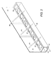
- Figure 2 shows a further example of known support arrangement in which a cavity forming member 30 in conjunction with the base 12 defines a cavity 31 into which, in use, concrete can be poured via openings 37. Openings 38 and the upper surface of the cavity enable air from within the cavity to be expelled as the concrete flows from side 16 through openings 37 into the cavity 31.
- the support elements may have additional webs 39 to secure the upper portion of the support element against the concrete pressure during curing. Openings 37 and 38 are sized to allow concrete to flow through opening 37, for air to escape the cavity 31 via openings 38, but opening 38 is sized to prevent significant overflow of the concrete outside of the cavity 31.
- Figure 3 illustrates one example of the present invention in which a shell 40, formed of upper 41 and lower 42 moldings, acts both as the support angle and the cavity forming member shown in the previous examples.
- the upper molding is substantially L-shaped having a substantially vertical (when in use) support section 43 and a substantially horizontal element 44 connected to the vertical element 43 via an angled corner 45.
- the opposite end of the lower section 44 is formed with a foot 46 which is shaped to engage with a correspondingly shaped portion 47 on the lower molding 42. From position 47, the lower molding 42 then continues down to a base 48 which typically rests on timber or concrete decking 70.
- a support tie 49 (in the figure only one is shown, but several will be used in the same way as support ties 15 from Figures 1 and 2 ) extends from a cavity 50 defined by the lower molding 42 and the substantially horizontal portion 44 of the upper molding 41 to a first side 51 of the substantially vertical support section 43.
- the support tie 49 is sized and positioned such that, in use, the angled corner 45 abuts against a portion of the support tie in order to provide support to the upper molding 41.
- the lower portion of the support tie 49 may, although it is not shown, be crimped or have holes or perforations formed therein thereby increasing the hold of the concrete (not shown) on the support tie 49. Similar formations may be provided on an upper portion of the support tie 49 above arm 53 which projects away from the upper edge of the support tie 49.
- the support tie 49 is provided with, in this example, two L-shaped projections 54 which engage with corresponding projections 55 provided on the first side 51 of the vertical support member 43.
- the position, orientation and shape of the projections is determined depending upon the relative sizes of the substantially vertical support section and the cavity 50, as if the support tie 49 is at a different angle with respect to the various elements, the retaining force that it provide, by way of the connections 54, 55, will be different.
- the angle of the arm 53, and the projections 55 are determined such that the substantially horizontal force on the vertical support section 43 and the vertical force provided on the horizontal portion 44 (both forces due to the poured concrete before it is cured) can be balanced, thereby preventing the upper molding 41 from being lifted upwardly and to the right in Figure 3 .
- the upper molding 41 tries to pivot around the connection with the lower molding 42, and the connection of the vertical support section to the support ties ensures that this does not happen.
- the substantially vertical section may be provided with a small tab 60 which is intended to prevent water ingress down surface 61, but any water which does run down surface 61 will be caught by a projection 62 which is upwardly angled and extends along the length of the support section 41.
- the base 48 of the lower molding 42 is similarly provided with a tab 63 and a further upstanding projection 64 for the same reasons.
- the support ties 49 may be connected to further reinforcing material 65 provided in the concrete prior to pouring.
- a blow hole 67 is provided in the lower portion 44 of the upper molding such that, as concrete is poured, air can be expelled from the cavity 50.
- Each tie 49 is preferably provided with a foot 68 which extends either or both of into and out of the page in Figure 3 and is connected to the main body of the tie via a weld 69.
- the foot 68 can then be fastened through the base 48 into the decking 70 on which the beam is being constructed.
- the foot may not be provided and/or other methods of increasing the bond between the tie and the settable material could be employed.
- brick or the blockwork 71 can be laid on top of the cavity section.
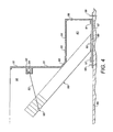
- FIG 4 shows an alternative embodiment in which shell 80 is formed from one integral part.
- the shell has a substantially vertical (when in use) section 81 and a substantially horizontal section 82, connected by a chamfered corner 83.
- Blow hole 84 is provided to allow air to escape from cavity 85 as concrete is poured to the left side of shell 80.
- a further vertical section 86 is connected to horizontal section 82, and descends to connect with base 87.
- a support tie 88 is shown having a foot 89, which is attached to the main section of the support tie by a weld 90, or by other suitable attachment means.
- a first channel 91 is provided toward the outer edge of the cavity and accommodates one end of the foot 89.
- connector 92 acts to hold the support tie 88 in the appropriate orientation during assembly of the system.
- connector 92 can be put in place to further provide support to the tie before and during pouring of the settable material. Bulbous end 94 of the connector 92 is located within channel 93 provided on vertical support 81. Connector 92 can then slide back and forth either into or out of the page as seen in Figure 4 , such that it can be aligned with support tie 88.
- the elongate body of connector 92 extends towards securing feature 95 on support tie 88, such that the connector is oriented at the chosen angle relative to support tie 88.
- Connector 92 may be made of a material having some elastic properties if so desired.
- the connector 92 may be made from an inelastic material such that it does not allow vertical support section 81 to move away from support tie 88. Connector 92 may alternatively be made from a rigid material to prevent vertical section 81 from moving either towards or away from support tie 88. Connector 92 may be made from separate parts whereby, for example, bulbous end 94 is separate from the elongate section and the securing means 95, and the parts are assembled together on site. Securing means 95 may be adjustable, as may the length of connector 92. Connector 92 may also be connected to vertical section 81 by some means other than channel 93.
- connector 92 acts to counter forces generated by pressure of the poured material acting against vertical section 81.
- the optimal angle for the connector 92 is determined depending upon the relative sizes of the substantially vertical support section 81 and the cavity 85, since if the support tie 88 is at a different angle with respect to the various elements, the retaining force that it provides by way of the connector 92 will be different.
- the angle of the connector 88 is determined such that the substantially horizontal force on the vertical support section 81 and the vertical force provided on the horizontal portion 82 (both forces due to the poured concrete before it is cured) can be balanced, thereby countering forces tending to lift the vertical section 81 and horizontal section 82 up and to the right in Figure 4 .
- the upper two walls 81 and 82 of the shell 80 try to pivot around the top and/or bottom of wall 86, and the connection of the vertical support section to the support ties helps to ensure that this does not happen.
- channel 97 Further support is provided by channel 97, provided towards the inner end of the base 87. This channel acts to retain the inner end of the foot 89 such that the pressure forces on vertical section 81 transferred to tie 88 through connector 92 are countered. Thus the tie 88 and vertical support 81 remain at the correct orientation with respect to the vertical in Figure 4 .
- Securing points 98 are provided such that the base 87 of shell 80 can be secured to the decking or concrete 99 underneath. These react the forces acting upon base 87 via channel 97. With a reduced need for fixings piercing the shell around cavity 85, the risk of water ingress to the cavity is greatly reduced. An additional benefit of the reduced risk of water ingress is that it is no longer necessary to use a non-corrodible material for tie 92 and foot 89. Thus cheaper corrodible metals may be may be used, reducing the cost of manufacture of the system.
- foot 89, and connector 92 can slide along their respective channels 91, 93 and 97, into or out of the page as seen in Figure 4 . This can be carried out irrespective of whether base 87 has been affixed to concrete or decking 90 via fixings 98 or not.
- tab 60 and projection 62 of Figure 3 may be provided on upper support section 81 to aid the prevention of water ingress.
- features equivalent to tab 63 and projection 64 in Figure 3 may also be provided on base 87 of shell 80.
- brick or blockwork 71 of Figure 3 can be laid on top of the cavity section 85 of Figure 4 .
Landscapes
- Engineering & Computer Science (AREA)
- Mining & Mineral Resources (AREA)
- Life Sciences & Earth Sciences (AREA)
- General Life Sciences & Earth Sciences (AREA)
- Paleontology (AREA)
- Civil Engineering (AREA)
- General Engineering & Computer Science (AREA)
- Structural Engineering (AREA)
- Forms Removed On Construction Sites Or Auxiliary Members Thereof (AREA)
- On-Site Construction Work That Accompanies The Preparation And Application Of Concrete (AREA)
Applications Claiming Priority (1)
| Application Number | Priority Date | Filing Date | Title |
|---|---|---|---|
| GBGB0711723.7A GB0711723D0 (en) | 2007-06-18 | 2007-06-18 | System for supporting concrete or other settable material |
Publications (1)
| Publication Number | Publication Date |
|---|---|
| EP2006455A1 true EP2006455A1 (de) | 2008-12-24 |
Family
ID=38332269
Family Applications (1)
| Application Number | Title | Priority Date | Filing Date |
|---|---|---|---|
| EP08158068A Withdrawn EP2006455A1 (de) | 2007-06-18 | 2008-06-11 | Schalungsträger |
Country Status (2)
| Country | Link |
|---|---|
| EP (1) | EP2006455A1 (de) |
| GB (2) | GB0711723D0 (de) |
Cited By (1)
| Publication number | Priority date | Publication date | Assignee | Title |
|---|---|---|---|---|
| GB2522887B (en) * | 2014-02-07 | 2020-11-25 | Abbey Pynford Holdings Ltd | Shuttering system |
Families Citing this family (1)
| Publication number | Priority date | Publication date | Assignee | Title |
|---|---|---|---|---|
| GB2522886B (en) * | 2014-02-07 | 2020-03-25 | Abbey Pynford Holdings Ltd | Shuttering system |
Citations (6)
| Publication number | Priority date | Publication date | Assignee | Title |
|---|---|---|---|---|
| US3819143A (en) * | 1968-11-04 | 1974-06-25 | Hambro Structural Systems Ltd | Formwork for concrete walls |
| US3977646A (en) * | 1974-09-05 | 1976-08-31 | Madison Materials Co. | Apparatus for molding concrete girders |
| US4151694A (en) * | 1977-06-22 | 1979-05-01 | Roll Form Products, Inc. | Floor system |
| DE10222907A1 (de) * | 2001-02-26 | 2003-03-13 | Domres Kai | Gebäudefundament und dessen Verfahren zur Anwendung |
| EP1609915A1 (de) | 2004-06-24 | 2005-12-28 | Paul Kiss | Randschalung zur Herstellung einer Flachgründung |
| EP1741840A2 (de) | 2005-07-04 | 2007-01-10 | Abbey Pynford Holdings plc | Stützvorrichtung |
Family Cites Families (4)
| Publication number | Priority date | Publication date | Assignee | Title |
|---|---|---|---|---|
| JPH0913390A (ja) * | 1995-06-29 | 1997-01-14 | Kanegafuchi Chem Ind Co Ltd | コンクリート基礎あるいは壁体の構築方法 |
| GB2399098B (en) * | 2003-03-04 | 2007-04-25 | Roxbury Ltd | Forming building foundations |
| GB2423533B (en) * | 2005-02-24 | 2009-09-23 | Clive Nightingale | Foundation base |
| JP3899493B1 (ja) * | 2006-02-22 | 2007-03-28 | 健司 松井 | 断熱基礎および断熱基礎の構築方法 |
-
2007
- 2007-06-18 GB GBGB0711723.7A patent/GB0711723D0/en not_active Ceased
-
2008
- 2008-06-11 GB GB0810654A patent/GB2450401B/en not_active Expired - Fee Related
- 2008-06-11 EP EP08158068A patent/EP2006455A1/de not_active Withdrawn
Patent Citations (6)
| Publication number | Priority date | Publication date | Assignee | Title |
|---|---|---|---|---|
| US3819143A (en) * | 1968-11-04 | 1974-06-25 | Hambro Structural Systems Ltd | Formwork for concrete walls |
| US3977646A (en) * | 1974-09-05 | 1976-08-31 | Madison Materials Co. | Apparatus for molding concrete girders |
| US4151694A (en) * | 1977-06-22 | 1979-05-01 | Roll Form Products, Inc. | Floor system |
| DE10222907A1 (de) * | 2001-02-26 | 2003-03-13 | Domres Kai | Gebäudefundament und dessen Verfahren zur Anwendung |
| EP1609915A1 (de) | 2004-06-24 | 2005-12-28 | Paul Kiss | Randschalung zur Herstellung einer Flachgründung |
| EP1741840A2 (de) | 2005-07-04 | 2007-01-10 | Abbey Pynford Holdings plc | Stützvorrichtung |
Cited By (1)
| Publication number | Priority date | Publication date | Assignee | Title |
|---|---|---|---|---|
| GB2522887B (en) * | 2014-02-07 | 2020-11-25 | Abbey Pynford Holdings Ltd | Shuttering system |
Also Published As
| Publication number | Publication date |
|---|---|
| GB0711723D0 (en) | 2007-07-25 |
| GB2450401A (en) | 2008-12-24 |
| GB2450401B (en) | 2011-11-09 |
| GB0810654D0 (en) | 2008-07-16 |
Similar Documents
| Publication | Publication Date | Title |
|---|---|---|
| KR101560253B1 (ko) | 파일과 프리캐스트코핑부를 이용한 급속 교량 시공방법 | |
| US4885884A (en) | Building panel assembly | |
| CN102341546A (zh) | 混凝土锚固件 | |
| EP2935712B1 (de) | Stützenschuh | |
| US20030110715A1 (en) | Sandwich erection lift anchor with welding plate assembly | |
| KR100742577B1 (ko) | 복합 구조 프레임 시스템 | |
| CA3030895A1 (en) | Concrete form brace with multi-depth rebar positioning | |
| GB2460674A (en) | Masonry bracket | |
| US20020078646A1 (en) | Suspended concrete flooring system and method | |
| US8397464B2 (en) | Middle pour anchor bolt holder | |
| US5864999A (en) | Modular wall system | |
| US6526721B1 (en) | Fluid-impervious barrier/keyway form support apparatus, system and related method | |
| EP2006455A1 (de) | Schalungsträger | |
| EP1741840B1 (de) | Stützvorrichtung | |
| KR100775359B1 (ko) | 거푸집 조립체 및 이를 이용한 건축물 시공 방법 | |
| JP2009257006A (ja) | グラウンドアンカー工法 | |
| JP2008255724A (ja) | アンカーボルト付基礎構造の施工用治具 | |
| KR20160064745A (ko) | 법면에 시공된 조립식 다기능 안전계단 | |
| AU2009297184B2 (en) | Hanger system for cementitious building units | |
| KR200457690Y1 (ko) | 지반보강용 블록 | |
| EP1609915A1 (de) | Randschalung zur Herstellung einer Flachgründung | |
| JPH11280063A (ja) | 杭頭構造および杭頭金物 | |
| JP5056534B2 (ja) | 水勾配床の構造物据付け方法 | |
| KR200298097Y1 (ko) | 거푸집 지지구조 | |
| KR200397826Y1 (ko) | 일체형 거푸집 지지장치 |
Legal Events
| Date | Code | Title | Description |
|---|---|---|---|
| PUAI | Public reference made under article 153(3) epc to a published international application that has entered the european phase |
Free format text: ORIGINAL CODE: 0009012 |
|
| AK | Designated contracting states |
Kind code of ref document: A1 Designated state(s): AT BE BG CH CY CZ DE DK EE ES FI FR GB GR HR HU IE IS IT LI LT LU LV MC MT NL NO PL PT RO SE SI SK TR |
|
| AX | Request for extension of the european patent |
Extension state: AL BA MK RS |
|
| AKX | Designation fees paid | ||
| REG | Reference to a national code |
Ref country code: DE Ref legal event code: 8566 |
|
| STAA | Information on the status of an ep patent application or granted ep patent |
Free format text: STATUS: THE APPLICATION IS DEEMED TO BE WITHDRAWN |
|
| 18D | Application deemed to be withdrawn |
Effective date: 20090625 |