EP2006488A2 - Axialstromfluidvorrichtung und schaufel - Google Patents
Axialstromfluidvorrichtung und schaufel Download PDFInfo
- Publication number
- EP2006488A2 EP2006488A2 EP07737806A EP07737806A EP2006488A2 EP 2006488 A2 EP2006488 A2 EP 2006488A2 EP 07737806 A EP07737806 A EP 07737806A EP 07737806 A EP07737806 A EP 07737806A EP 2006488 A2 EP2006488 A2 EP 2006488A2
- Authority
- EP
- European Patent Office
- Prior art keywords
- blade
- fluid
- pressure surface
- trailing edge
- exposed
- Prior art date
- Legal status (The legal status is an assumption and is not a legal conclusion. Google has not performed a legal analysis and makes no representation as to the accuracy of the status listed.)
- Withdrawn
Links
Images


Classifications
-
- F—MECHANICAL ENGINEERING; LIGHTING; HEATING; WEAPONS; BLASTING
- F01—MACHINES OR ENGINES IN GENERAL; ENGINE PLANTS IN GENERAL; STEAM ENGINES
- F01D—NON-POSITIVE DISPLACEMENT MACHINES OR ENGINES, e.g. STEAM TURBINES
- F01D5/00—Blades; Blade-carrying members; Heating, heat-insulating, cooling or antivibration means on the blades or the members
- F01D5/12—Blades
- F01D5/14—Form or construction
- F01D5/147—Construction, i.e. structural features, e.g. of weight-saving hollow blades
-
- F—MECHANICAL ENGINEERING; LIGHTING; HEATING; WEAPONS; BLASTING
- F01—MACHINES OR ENGINES IN GENERAL; ENGINE PLANTS IN GENERAL; STEAM ENGINES
- F01D—NON-POSITIVE DISPLACEMENT MACHINES OR ENGINES, e.g. STEAM TURBINES
- F01D5/00—Blades; Blade-carrying members; Heating, heat-insulating, cooling or antivibration means on the blades or the members
- F01D5/12—Blades
- F01D5/14—Form or construction
- F01D5/141—Shape, i.e. outer, aerodynamic form
- F01D5/145—Means for influencing boundary layers or secondary circulations
-
- F—MECHANICAL ENGINEERING; LIGHTING; HEATING; WEAPONS; BLASTING
- F04—POSITIVE - DISPLACEMENT MACHINES FOR LIQUIDS; PUMPS FOR LIQUIDS OR ELASTIC FLUIDS
- F04D—NON-POSITIVE-DISPLACEMENT PUMPS
- F04D29/00—Details, component parts, or accessories
- F04D29/26—Rotors specially for elastic fluids
- F04D29/32—Rotors specially for elastic fluids for axial flow pumps
- F04D29/321—Rotors specially for elastic fluids for axial flow pumps for axial flow compressors
- F04D29/324—Blades
-
- F—MECHANICAL ENGINEERING; LIGHTING; HEATING; WEAPONS; BLASTING
- F04—POSITIVE - DISPLACEMENT MACHINES FOR LIQUIDS; PUMPS FOR LIQUIDS OR ELASTIC FLUIDS
- F04D—NON-POSITIVE-DISPLACEMENT PUMPS
- F04D29/00—Details, component parts, or accessories
- F04D29/26—Rotors specially for elastic fluids
- F04D29/32—Rotors specially for elastic fluids for axial flow pumps
- F04D29/38—Blades
- F04D29/384—Blades characterised by form
-
- F—MECHANICAL ENGINEERING; LIGHTING; HEATING; WEAPONS; BLASTING
- F04—POSITIVE - DISPLACEMENT MACHINES FOR LIQUIDS; PUMPS FOR LIQUIDS OR ELASTIC FLUIDS
- F04D—NON-POSITIVE-DISPLACEMENT PUMPS
- F04D29/00—Details, component parts, or accessories
- F04D29/66—Combating cavitation, whirls, noise, vibration or the like; Balancing
- F04D29/68—Combating cavitation, whirls, noise, vibration or the like; Balancing by influencing boundary layers
- F04D29/681—Combating cavitation, whirls, noise, vibration or the like; Balancing by influencing boundary layers especially adapted for elastic fluid pumps
- F04D29/682—Combating cavitation, whirls, noise, vibration or the like; Balancing by influencing boundary layers especially adapted for elastic fluid pumps by fluid extraction
-
- F—MECHANICAL ENGINEERING; LIGHTING; HEATING; WEAPONS; BLASTING
- F04—POSITIVE - DISPLACEMENT MACHINES FOR LIQUIDS; PUMPS FOR LIQUIDS OR ELASTIC FLUIDS
- F04D—NON-POSITIVE-DISPLACEMENT PUMPS
- F04D29/00—Details, component parts, or accessories
- F04D29/66—Combating cavitation, whirls, noise, vibration or the like; Balancing
- F04D29/68—Combating cavitation, whirls, noise, vibration or the like; Balancing by influencing boundary layers
- F04D29/681—Combating cavitation, whirls, noise, vibration or the like; Balancing by influencing boundary layers especially adapted for elastic fluid pumps
- F04D29/684—Combating cavitation, whirls, noise, vibration or the like; Balancing by influencing boundary layers especially adapted for elastic fluid pumps by fluid injection
-
- F—MECHANICAL ENGINEERING; LIGHTING; HEATING; WEAPONS; BLASTING
- F05—INDEXING SCHEMES RELATING TO ENGINES OR PUMPS IN VARIOUS SUBCLASSES OF CLASSES F01-F04
- F05D—INDEXING SCHEME FOR ASPECTS RELATING TO NON-POSITIVE-DISPLACEMENT MACHINES OR ENGINES, GAS-TURBINES OR JET-PROPULSION PLANTS
- F05D2260/00—Function
- F05D2260/96—Preventing, counteracting or reducing vibration or noise
-
- Y—GENERAL TAGGING OF NEW TECHNOLOGICAL DEVELOPMENTS; GENERAL TAGGING OF CROSS-SECTIONAL TECHNOLOGIES SPANNING OVER SEVERAL SECTIONS OF THE IPC; TECHNICAL SUBJECTS COVERED BY FORMER USPC CROSS-REFERENCE ART COLLECTIONS [XRACs] AND DIGESTS
- Y02—TECHNOLOGIES OR APPLICATIONS FOR MITIGATION OR ADAPTATION AGAINST CLIMATE CHANGE
- Y02T—CLIMATE CHANGE MITIGATION TECHNOLOGIES RELATED TO TRANSPORTATION
- Y02T50/00—Aeronautics or air transport
- Y02T50/60—Efficient propulsion technologies, e.g. for aircraft
-
- Y—GENERAL TAGGING OF NEW TECHNOLOGICAL DEVELOPMENTS; GENERAL TAGGING OF CROSS-SECTIONAL TECHNOLOGIES SPANNING OVER SEVERAL SECTIONS OF THE IPC; TECHNICAL SUBJECTS COVERED BY FORMER USPC CROSS-REFERENCE ART COLLECTIONS [XRACs] AND DIGESTS
- Y10—TECHNICAL SUBJECTS COVERED BY FORMER USPC
- Y10S—TECHNICAL SUBJECTS COVERED BY FORMER USPC CROSS-REFERENCE ART COLLECTIONS [XRACs] AND DIGESTS
- Y10S416/00—Fluid reaction surfaces, i.e. impellers
- Y10S416/50—Vibration damping features
Definitions
- the present invention relates to an axial flow fluid apparatus in which fluid flows axially, and blades are exposed into the fluid.
- axial flow fluid apparatuses in which fluid flows axially, there is one in which a moving blade row and a stationary blade row are axially arranged.
- a jet engine, a compressor, and a turbine can be mentioned.
- the moving blade row includes a plurality of moving blades
- the stationary blade row includes a plurality of stationary blades.
- a velocity defect region where a stream of air is slow in comparison to surrounding regions is created on the downstream of the moving blades.
- the stream in this velocity defect region is generally called wake.
- the width of the stream becomes narrow, and the velocity defect becomes strong, and the velocity defect becomes strong just behind of the moving blades. Where the width of the stream becomes wide, the velocity defect becomes weak further away from the moving blades.
- noise or vibration is generated as a wake resulting from the moving blades interferes with the stationary blade. It is known that this noise or vibration becomes large when the wake is strong, i.e. the velocity defect is large, and becomes small when the wake is weak i.e., the velocity defect is small.
- Patent Document 1 Japanese Unexamined Patent Application Publication No. 2003-227302 .
- Patent Document 2 U.S. Patent No.6004095
- Patent Document 1 when the spacing between the moving blade row and the stationary blade row is widened, the axial length of the axial flow fluid apparatus becomes long, and a casing or the like corresponding to the axial length is required. Therefore, the weight of the apparatus may increase or the apparatus may be enlarged. Further, if an increase in weight or enlargement of the apparatus is not allowed, the invention described in Patent Document 1 cannot be used.
- the present invention has been made in view of the above problems, and aims to reliably reduce noise or vibration without complicating a mechanism.
- the axial flow fluid apparatus of the present invention is an axial flow fluid apparatus axially provided with a plurality of blade rows having a plurality of blades arranged around a shaft.
- a fluid passage for jetting a fluid to a downstream velocity defect region resulting from the blade is formed in at least one of the blades constituting a blade row installed on the upstream side of the plurality of blade rows so as to lead from a positive pressure surface to a negative pressure surface or a trailing edge.
- part of the fluid which flows to the downstream via an upstream blade row is jetted to the velocity defect region via the fluid passage.
- the fluid is introduced into the fluid passage by utilizing the differential pressure between the pressure on the side of the positive pressure surface and the pressure on the side of the negative pressure surface, and this introduced fluid is jetted to the velocity defect region.
- the fluid passage includes a fluid introducing port formed so as to be exposed to the positive pressure surface of the blade, a fluid jet port formed in the negative pressure surface or the trailing edge of the blade, and a passage portion connecting the fluid introducing port and the fluid jet port can be adopted.
- the fluid passage includes a fluid introducing port formed so as to be exposed to the positive pressure surface of the blade, a fluid jet port formed so as to be exposed to the negative pressure surface or the trailing edge of the blade, and the inside of the blade can be adopted.
- the fluid introducing port is formed relatively closer to the leading edge of the blade, and the fluid jet port is formed relatively closer to the trailing edge of the blade can be adopted.
- the blade of the present invention is a blade exposed into a fluid.
- a fluid passage for jetting a fluid to a downstream velocity defect region resulting from the blade is formed so as to lead from a positive pressure surface to a negative pressure surface or a trailing edge.
- part of the fluid which flows from the upstream of the blade to the downstream thereof is jetted to the velocity defect region via the fluid passage.
- the fluid is introduced into the fluid passage by utilizing the differential pressure between the pressure on the side of the positive pressure surface and the pressure on the side of the negative pressure surface, and this introduced fluid is jetted to the velocity defect region.
- the fluid passage includes a fluid introducing port formed so as to be exposed to the positive pressure surface, a fluid jet port formed in the negative pressure surface or trailing edge, and a passage portion connecting the fluid introducing port and the fluid jet port can be adopted.
- the fluid passage includes a fluid introducing port formed so as to be exposed to the positive pressure surface, to a fluid jet port formed so as to be exposed to the negative pressure surface or the trailing edge, and to the inside can be adopted.
- the fluid introducing port is formed relatively closer to the leading edge of the blade, and the fluid jet port is formed relatively closer to the trailing edge of the blade can be adopted.
- part of the fluid which flows from the upstream of the blade to the downstream thereof is jetted to the velocity defect region via the fluid passage. For this reason, it is possible to weaken the wake and to reduce the noise or vibration.
- the fluid is introduced into the fluid passage by utilizing the differential pressure between the pressure on the side of the positive pressure surface and the pressure on the side of the negative pressure surface, and this introduced fluid is jetted to the velocity defect region. Therefore, it is not necessary to introduce outside air into the inside of the apparatus, and it is possible to jet a fluid to the velocity defect region by a simple mechanism.
- FIGS. 1 and 2 are sectional views schematically showing the schematic configuration of the jet engine 1 of this embodiment.
- FIG. 1 is a sectional view when the jet engine 1 is cut along an axial direction L
- FIG 2 is a sectional view (sectional view in a plane orthogonal in the axial direction L) taken along an A-A line of FIG 1 .
- the jet engine 1 of this embodiment includes a casing 2, a moving blade row 3 (blade row), a stationary blade row 4 (blade row), a combustion chamber 5, a turbine blade row 6, and a shaft 7.
- the casing 2 forms the appearance of the jet engine 1, and has the moving blade row 3, the stationary blade row 4, the combustion chamber 5, the turbine blade row 6, and the shaft 7 stored therein. Opposite ends of the casing 2 in the axial direction L are opened. An opening at one end of the casing is used as an intake port 21 for introducing ambient air into the jet engine 1, and an opening at the other end of the casing is used as a jetting port 22 which jets a combustion gas Z from the jet engine 1. Further, a flow passage 23 which connects the intake port 21 and the jetting port 22 is formed in the axial direction L inside the casing 2.
- the moving blade row 3 includes a plurality of moving blades 31 (blades) which are arranged around a shaft.
- Each moving blade 31 is installed in the flow passage 23 formed inside the casing 2 with a negative pressure surface directed toward the intake port 21, and a positive pressure surface directed toward the jetting port 22, and each moving blade 31 is fixed to a shaft 7 installed to extend in the axial direction L.
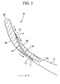
- FIG. 3 is a view schematically showing a cross-section of the moving blade 31.
- the moving blade 31 has a leading edge 32 located at the intake port 21 and a trailing edge 33 located at the jetting port 22, and is thereby installed in a state where a negative pressure surface 34 and a positive pressure surface 35 are inclined with respect to the axial direction L.
- the moving blade 31 of this embodiment is formed with a fluid passage 10 which jets air Y to wake X (velocity defect region) formed on the downstream of the moving blade 31 in a case where the moving blade 31 is exposed into a fluid.
- the fluid passage 10 includes an opening 11 (fluid introducing port) formed so as to be exposed to the positive pressure surface 35 of the moving blade 31, an opening 12 (fluid jet port) formed in the negative pressure surface 34 of the moving blade 31, and a passage portion 13 which connects the opening 11 and the opening 12. That is, the fluid passage 10 is formed so as to lead from the positive pressure surface 35 of the moving blade 31 to the negative pressure surface 34 thereof.
- a plurality of such fluid passages 10 are formed in each moving blade 31.
- the opening 11 of the fluid passage 10, as shown in FIG 4 is formed near the leading edge 32 of the moving blade 31. Further, the opening 12 of the fluid passage 10, as shown in FIG 5 , is formed near the trailing edge 33 of the moving blade 31. Also, the passage portion 13 is formed inside the moving blade 31 so as to connect the opening 11 and the opening 12 substantially in a straight line.
- the shape of the opening 12 and the passage portion 13 is set such that the air Y to be jet is directed to the wake X.
- a plurality of openings 11 are arranged in one row in the width direction of the moving blade 31 in the positive pressure surface 35, and as shown in FIG 5 , a plurality of openings 12 are arranged in one row in the width direction of the moving blade 31 in the negative pressure surface 34.
- the stationary blade row 4 is installed on the downstream of the moving blade row 3, and is installed apart from the moving blade row 3.
- the stationary blade row 4 includes a plurality of stationary blades 41 which are arranged around the shaft.
- Each stationary blade 41 is installed in the flow passage 23 formed inside the casing 2, and is fixed to the casing 2 at an angle such that the stationary blade rectifies the air Y supplied from the moving blade row 3, and the air Y does not flow back from the downstream side.
- the combustion chamber 5 is installed on the downstream of the stationary blade row 4.
- the combustion chamber 5 is formed as apart of the flow passage 23 of the casing 2 is widened. Supply of fuel to the combustion chamber 5 from the outside is allowed, and an ignition device which is not shown is installed in the combustion chamber 5.
- the air Y which is supplied toward the stationary blade row 4 is combusted after being mixed with fuel. Then, combustion gas Z generated by combustion is exhausted to the flow passage 23 from the combustion chamber 5.
- the turbine blade row 6 is installed on the downstream of the combustion chamber 5, and includes a plurality of turbine blades 61 which are arranged around the shaft.
- Each turbine blade 61 is installed in the flow passage 23 formed inside the casing 2, and is fixed to the shaft 7 at an angle such that it receives combustion gas Z supplied from the combustion chamber 5 side so as to give rotational power in a predetermined direction to the shaft 7.
- the shaft 7, as described above, is installed so as to extend in the axial direction L, and has each moving blade 31 and each turbine blade 61 fixed thereto.
- the shaft 7 is fixed to the casing 2 via a bearing which is not shown.
- the air Y introduced into the jet engine 1 is compressed by way of the moving blades 31 and the stationary blades 41, and is then supplied to the combustion chamber 5.
- the air Y supplied to the combustion chamber 5 is mixed with fuel and combusted, in the combustion chamber 5.
- combustion gas Z is generated.
- the jet engine 1 obtains thrust as the combustion gas Z is jetted from the jetting port 22.
- the combustion gas Z goes through the turbine blades 61 from the combustion chamber 5 to the jetting port 22.
- the turbine blades 61 give rotational power in one direction to the shaft 7 as receiving the combustion gas Z. As a result, since the shaft 7 is rotated, it is possible to continue rotating the moving blades 31 fixed to the shaft 7.
- the stream of the air Y is formed as the moving blades 31 are rotated. That is, the moving blades 31 are relatively exposed into the stream of the air Y. For this reason, as shown in FIG 3 , the wake X which faces the extension direction of the moving blade 31 from the trailing edge 33 is formed on the downstream of the moving blade 31.
- the fluid passage 10 for jetting the air Y to the wake X is formed in a moving blade 31 constituting the upstream blade row (moving blade row 3) of a plurality of blade rows (the moving blade row 3 and the stationary blade row 4).
- the wake X is a region where a velocity defect is large, i.e., a stream of air is slow in comparison to surrounding regions. For this reason, a velocity defect is alleviated and speed of the jet engine 1 increases as the air Y is jetted from the fluid passage 10 to the wake X, and thereby, the wake X becomes weaker.
- the noise or vibration which is generated as the wake X interferes with the stationary blades 41 becomes large when the wake is strong, and becomes small when the wake is weak. For this reason, like the jet engine 1 of this embodiment, it is possible to reduce the noise or vibration by weakening the wake X.
- the fluid passage 10 is formed so as to lead from the positive pressure surface 35 of the moving blade 31 to the negative pressure surface 34 thereof.
- the air Y can be introduced into the fluid passage 10 using the differential pressure between the pressure on the side of the positive pressure surface 35 and the pressure on the side of the negative pressure surface 34, and this introduced air Y is jetted to the wake X. Therefore, it is not necessary to introduce the air outside the flow passage 23 into the inside of the apparatus, or to install forced circulating means, such as a pump. That is, in the jet engine 1 of this embodiment, the air Y can be jetted to the wake X by a simple mechanism.
- jet engine 1 of this embodiment it is possible to reliably reduce noise or vibration without complicating the mechanism.
- the opening 11 (opening for introducing the air Y into the passage portion 13) formed so as to be exposed to the positive pressure surface 35 of the moving blade 31 is formed near the leading edge 32
- the opening 12 (opening for jetting the air Y from the passage portion 13) formed so as to be exposed to the negative pressure surface 34 of the moving blade 31 is formed near the trailing edge 33.
- the passage portion 13 which connects the opening 11 and the opening 12 can be formed substantially in a straight line toward the wake X.
- a plurality of openings 11 are arranged in one row in the width direction of the moving blade 31 in the positive pressure surface 35, and as shown in FIG 5 , a plurality of openings 12 are arranged in one row in the width direction of the moving blade 31 in the negative pressure surface 34.
- the present invention is not limited thereto.
- the opening 11 and the opening 12 may be arranged in two rows.
- rectangular openings 14 and 15 which extend in the width direction of the moving blade 31 may be formed, respectively, instead of the plurality of openings 11 and 12.
- one passage portion 13 which connects the opening 14 and the opening 15 is also formed.
- the opening 12 opening for jetting the air Y from the passage portion 13
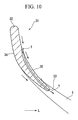
- the opening 12 is not necessarily formed so as to be exposed to the negative pressure surface 34 of the moving blade 31, and as shown in FIG. 10 , the opening 12 may be formed so as to be exposed to the trailing edge 33 of the moving blade 31. Even in such a case, the air Y can be jetted to the wake X.
- a hollow moving blade 81 is fixed to the shaft 7 instead of the moving blade 31 provided in the jet engine 1 of the above embodiment.
- FIG. 11 is a view schematically showing a cross-section of the moving blade 81 provided in the jet engine of this embodiment.
- the inside 82 of the moving blade 81 is made hollow.
- the fluid passage 10 includes the opening 11 formed so as to be exposed to a positive pressure surface 84 of the moving blade 81, to the opening 12 formed so as to be exposed to a negative pressure surface 83 of the moving blade 81, and to the inside 82 of the moving blade 81.
- the jet engine has been described as an example of the axial flow fluid apparatus of the invention.
- the present invention is not limited to this, and the invention can also be applied to the axial flow fluid apparatus, such as a compressor or a turbine.
Landscapes
- Engineering & Computer Science (AREA)
- Mechanical Engineering (AREA)
- General Engineering & Computer Science (AREA)
- Physics & Mathematics (AREA)
- Fluid Mechanics (AREA)
- Architecture (AREA)
- Structures Of Non-Positive Displacement Pumps (AREA)
- Turbine Rotor Nozzle Sealing (AREA)
Applications Claiming Priority (2)
| Application Number | Priority Date | Filing Date | Title |
|---|---|---|---|
| JP2006106158A JP2007278187A (ja) | 2006-04-07 | 2006-04-07 | 軸流流体装置及び翼 |
| PCT/JP2007/054231 WO2007116621A1 (ja) | 2006-04-07 | 2007-03-05 | 軸流流体装置及び翼 |
Publications (3)
| Publication Number | Publication Date |
|---|---|
| EP2006488A2 true EP2006488A2 (de) | 2008-12-24 |
| EP2006488A9 EP2006488A9 (de) | 2009-07-22 |
| EP2006488A4 EP2006488A4 (de) | 2013-04-17 |
Family
ID=38580923
Family Applications (1)
| Application Number | Title | Priority Date | Filing Date |
|---|---|---|---|
| EP07737806.5A Withdrawn EP2006488A4 (de) | 2006-04-07 | 2007-03-05 | Axialstromfluidvorrichtung und schaufel |
Country Status (4)
| Country | Link |
|---|---|
| US (1) | US8133008B2 (de) |
| EP (1) | EP2006488A4 (de) |
| JP (1) | JP2007278187A (de) |
| WO (1) | WO2007116621A1 (de) |
Cited By (7)
| Publication number | Priority date | Publication date | Assignee | Title |
|---|---|---|---|---|
| ITMI20130791A1 (it) * | 2013-05-14 | 2014-11-15 | Cofimco Srl | Ventilatore assiale |
| FR3019209A1 (fr) * | 2014-03-27 | 2015-10-02 | Snecma | Aube mobile comportant des moyens reducteurs de bruit |
| FR3027354A1 (fr) * | 2014-10-17 | 2016-04-22 | Snecma | Roue a aubes comprenant des percages entre l'intrados et l'extrados de l'aube et moteur associe |
| EP3246520A2 (de) * | 2016-05-16 | 2017-11-22 | United Technologies Corporation | Verfahren und vorrichtung zur verbesserung des laminarstroms für gasturbinenmotorkomponenten |
| CN107514292A (zh) * | 2017-09-30 | 2017-12-26 | 南京赛达机械制造有限公司 | 一种抗扭断汽轮机叶片 |
| FR3079552A1 (fr) * | 2018-03-29 | 2019-10-04 | Safran Aircraft Engines | Turbomachine comportant au moins une aube amont comportant une portion de soufflage pour limiter la resonance d'une aube aval |
| EP3063374B1 (de) * | 2013-10-31 | 2023-07-19 | Raytheon Technologies Corporation | Gasturbinentriebwerk und verfahren zum betreiben eines gasturbinentriebwerks |
Families Citing this family (13)
| Publication number | Priority date | Publication date | Assignee | Title |
|---|---|---|---|---|
| GB2481822B (en) * | 2010-07-07 | 2013-09-18 | Rolls Royce Plc | Rotor blade |
| KR101324249B1 (ko) * | 2011-12-06 | 2013-11-01 | 삼성테크윈 주식회사 | 스퀼러 팁이 형성된 블레이드를 구비한 터빈 임펠러 |
| US20140215998A1 (en) * | 2012-10-26 | 2014-08-07 | Honeywell International Inc. | Gas turbine engines with improved compressor blades |
| JP6577400B2 (ja) * | 2016-03-30 | 2019-09-18 | 三菱日立パワーシステムズ株式会社 | タービン動翼 |
| US10731469B2 (en) * | 2016-05-16 | 2020-08-04 | Raytheon Technologies Corporation | Method and apparatus to enhance laminar flow for gas turbine engine components |
| US10519976B2 (en) * | 2017-01-09 | 2019-12-31 | Rolls-Royce Corporation | Fluid diodes with ridges to control boundary layer in axial compressor stator vane |
| KR101757440B1 (ko) * | 2017-01-24 | 2017-07-12 | 이제이콥부희 | 캐비테이션 펌프 유닛 |
| DE102017112742A1 (de) * | 2017-06-09 | 2018-12-13 | Wobben Properties Gmbh | Rotorblatt für eine Windenergieanlage und Windenergieanlage |
| TWI658213B (zh) * | 2018-08-13 | 2019-05-01 | 宏碁股份有限公司 | 軸流風扇 |
| CN109681475A (zh) * | 2018-12-28 | 2019-04-26 | 哈尔滨工业大学 | 高负荷压气机附面层非定常振荡抽吸流动控制方法 |
| JP7213103B2 (ja) * | 2019-02-26 | 2023-01-26 | 三菱重工業株式会社 | 翼及びこれを備えた機械 |
| US12320326B2 (en) * | 2022-06-03 | 2025-06-03 | Hamilton Sundstrand Corporation | Trailing edge noise reduction using an airfoil with an internal bypass channel |
| US12055057B2 (en) * | 2022-12-30 | 2024-08-06 | Pratt & Whitney Canada Corp. | Engine strut flow control |
Family Cites Families (14)
| Publication number | Priority date | Publication date | Assignee | Title |
|---|---|---|---|---|
| DE390486C (de) * | 1922-07-14 | 1924-02-20 | Rudolf Wagner Dr | Schaufel, insbesondere fuer Dampf- und Gasturbinen |
| US2340417A (en) * | 1941-10-07 | 1944-02-01 | Clyde E Ellett | Noiseless propeller |
| US2637487A (en) * | 1948-03-09 | 1953-05-05 | James G Sawyer | Blower |
| GB736835A (en) * | 1952-09-11 | 1955-09-14 | Maschf Augsburg Nuernberg Ag | Improvements in or relating to blading for axial flow turbo-engines |
| US3298636A (en) * | 1965-01-15 | 1967-01-17 | Arnholdt Eric | Airfoil |
| JPS6050119B2 (ja) | 1978-11-09 | 1985-11-06 | 松下電器産業株式会社 | スピ−カ装置 |
| JPH07243397A (ja) | 1994-03-02 | 1995-09-19 | Matsushita Refrig Co Ltd | 送風機 |
| JPH0979187A (ja) * | 1995-09-13 | 1997-03-25 | Matsushita Electric Ind Co Ltd | 軸流送風機羽根車 |
| US6004095A (en) | 1996-06-10 | 1999-12-21 | Massachusetts Institute Of Technology | Reduction of turbomachinery noise |
| GB0001399D0 (en) * | 2000-01-22 | 2000-03-08 | Rolls Royce Plc | An aerofoil for an axial flow turbomachine |
| JP2003161104A (ja) * | 2001-11-26 | 2003-06-06 | Ishikawajima Harima Heavy Ind Co Ltd | タービン翼 |
| JP2003227302A (ja) | 2002-02-04 | 2003-08-15 | Ishikawajima Harima Heavy Ind Co Ltd | 伴流混合促進翼 |
| JP2005240749A (ja) | 2004-02-27 | 2005-09-08 | Mitsubishi Electric Corp | 送風機 |
| JP4123212B2 (ja) | 2004-10-01 | 2008-07-23 | 松下電器産業株式会社 | ネットワーク機能を有するプロジェクタ投射システム |
-
2006
- 2006-04-07 JP JP2006106158A patent/JP2007278187A/ja active Pending
-
2007
- 2007-03-05 EP EP07737806.5A patent/EP2006488A4/de not_active Withdrawn
- 2007-03-05 US US12/296,191 patent/US8133008B2/en active Active
- 2007-03-05 WO PCT/JP2007/054231 patent/WO2007116621A1/ja not_active Ceased
Cited By (9)
| Publication number | Priority date | Publication date | Assignee | Title |
|---|---|---|---|---|
| ITMI20130791A1 (it) * | 2013-05-14 | 2014-11-15 | Cofimco Srl | Ventilatore assiale |
| WO2014184727A1 (en) * | 2013-05-14 | 2014-11-20 | Cofimco S.R.L. | Axial fan |
| US10036392B2 (en) | 2013-05-14 | 2018-07-31 | Cofimco S.R.L. | Axial fan for industrial use |
| EP3063374B1 (de) * | 2013-10-31 | 2023-07-19 | Raytheon Technologies Corporation | Gasturbinentriebwerk und verfahren zum betreiben eines gasturbinentriebwerks |
| FR3019209A1 (fr) * | 2014-03-27 | 2015-10-02 | Snecma | Aube mobile comportant des moyens reducteurs de bruit |
| FR3027354A1 (fr) * | 2014-10-17 | 2016-04-22 | Snecma | Roue a aubes comprenant des percages entre l'intrados et l'extrados de l'aube et moteur associe |
| EP3246520A2 (de) * | 2016-05-16 | 2017-11-22 | United Technologies Corporation | Verfahren und vorrichtung zur verbesserung des laminarstroms für gasturbinenmotorkomponenten |
| CN107514292A (zh) * | 2017-09-30 | 2017-12-26 | 南京赛达机械制造有限公司 | 一种抗扭断汽轮机叶片 |
| FR3079552A1 (fr) * | 2018-03-29 | 2019-10-04 | Safran Aircraft Engines | Turbomachine comportant au moins une aube amont comportant une portion de soufflage pour limiter la resonance d'une aube aval |
Also Published As
| Publication number | Publication date |
|---|---|
| WO2007116621A1 (ja) | 2007-10-18 |
| EP2006488A4 (de) | 2013-04-17 |
| EP2006488A9 (de) | 2009-07-22 |
| JP2007278187A (ja) | 2007-10-25 |
| US8133008B2 (en) | 2012-03-13 |
| US20090220332A1 (en) | 2009-09-03 |
Similar Documents
| Publication | Publication Date | Title |
|---|---|---|
| EP2006488A2 (de) | Axialstromfluidvorrichtung und schaufel | |
| US8186962B2 (en) | Fan rotating blade for turbofan engine | |
| US9790797B2 (en) | Subsonic swept fan blade | |
| US8578700B2 (en) | Gas turbine engine with fluid mixing arrangement | |
| US20090304518A1 (en) | Turbofan engine | |
| US8251649B2 (en) | Blade row of axial flow type compressor | |
| US9790957B2 (en) | Air intake duct structure for centrifugal fluid machine | |
| JP4862961B2 (ja) | 騒音低減装置及びジェット推進システム | |
| US10287024B2 (en) | Direct drive aft fan engine | |
| CN107923342B (zh) | 包括推力反向装置的飞行器推进组件 | |
| KR20120075490A (ko) | 터빈 동익 및 터보 기계 | |
| EP3002210B1 (de) | Triebwerksgondel | |
| US20200240278A1 (en) | Inter-turbine ducts with flow control mechanisms | |
| JP5055179B2 (ja) | 軸流式圧縮機のケーシング | |
| EP3090952B1 (de) | Triebwerksgondel | |
| WO2008058368A1 (en) | Nacelle drag reduction device for a turbofan gas turbine engine | |
| US20130156602A1 (en) | Film cooled turbine component | |
| JP2008075582A (ja) | V/stol機用推進システム | |
| JP4402503B2 (ja) | 風力機械のディフューザおよびディフューザ | |
| JP4446150B2 (ja) | ガスタービンパージエアの吹き出し方法及び吹き出し構造 | |
| KR20260015545A (ko) | 플랩을 이용한 선박용 풍력 보조 추진 시스템 | |
| KR20170002053U (ko) | 선박용 배기구의 연소가스 배출구조 | |
| US20170022996A1 (en) | Bypass duct fairing for low bypass ratio turbofan engine and turbofan engine therewith | |
| JP2008248734A (ja) | 軸流流体機械用翼 |
Legal Events
| Date | Code | Title | Description |
|---|---|---|---|
| PUAI | Public reference made under article 153(3) epc to a published international application that has entered the european phase |
Free format text: ORIGINAL CODE: 0009012 |
|
| PUAB | Information related to the publication of an a document modified or deleted |
Free format text: ORIGINAL CODE: 0009199EPPU |
|
| 17P | Request for examination filed |
Effective date: 20081010 |
|
| AK | Designated contracting states |
Kind code of ref document: A2 Designated state(s): DE FR GB IT |
|
| RBV | Designated contracting states (corrected) |
Designated state(s): DE FR GB IT |
|
| DAX | Request for extension of the european patent (deleted) | ||
| A4 | Supplementary search report drawn up and despatched |
Effective date: 20130314 |
|
| RIC1 | Information provided on ipc code assigned before grant |
Ipc: F04D 29/66 20060101ALI20130308BHEP Ipc: F04D 29/38 20060101ALI20130308BHEP Ipc: F01D 5/14 20060101AFI20130308BHEP |
|
| STAA | Information on the status of an ep patent application or granted ep patent |
Free format text: STATUS: THE APPLICATION IS DEEMED TO BE WITHDRAWN |
|
| 18D | Application deemed to be withdrawn |
Effective date: 20131015 |