EP2006935A1 - Dispositif electrique avec capot de film exterieur - Google Patents
Dispositif electrique avec capot de film exterieur Download PDFInfo
- Publication number
- EP2006935A1 EP2006935A1 EP07737866A EP07737866A EP2006935A1 EP 2006935 A1 EP2006935 A1 EP 2006935A1 EP 07737866 A EP07737866 A EP 07737866A EP 07737866 A EP07737866 A EP 07737866A EP 2006935 A1 EP2006935 A1 EP 2006935A1
- Authority
- EP
- European Patent Office
- Prior art keywords
- heat fusion
- negative electrode
- positive
- protection member
- film
- Prior art date
- Legal status (The legal status is an assumption and is not a legal conclusion. Google has not performed a legal analysis and makes no representation as to the accuracy of the status listed.)
- Granted
Links
Images

Classifications
-
- H—ELECTRICITY
- H01—ELECTRIC ELEMENTS
- H01M—PROCESSES OR MEANS, e.g. BATTERIES, FOR THE DIRECT CONVERSION OF CHEMICAL ENERGY INTO ELECTRICAL ENERGY
- H01M10/00—Secondary cells; Manufacture thereof
- H01M10/04—Construction or manufacture in general
- H01M10/0436—Small-sized flat cells or batteries for portable equipment
-
- H—ELECTRICITY
- H01—ELECTRIC ELEMENTS
- H01M—PROCESSES OR MEANS, e.g. BATTERIES, FOR THE DIRECT CONVERSION OF CHEMICAL ENERGY INTO ELECTRICAL ENERGY
- H01M50/00—Constructional details or processes of manufacture of the non-active parts of electrochemical cells other than fuel cells, e.g. hybrid cells
- H01M50/10—Primary casings; Jackets or wrappings
- H01M50/102—Primary casings; Jackets or wrappings characterised by their shape or physical structure
- H01M50/105—Pouches or flexible bags
-
- H—ELECTRICITY
- H01—ELECTRIC ELEMENTS
- H01M—PROCESSES OR MEANS, e.g. BATTERIES, FOR THE DIRECT CONVERSION OF CHEMICAL ENERGY INTO ELECTRICAL ENERGY
- H01M50/00—Constructional details or processes of manufacture of the non-active parts of electrochemical cells other than fuel cells, e.g. hybrid cells
- H01M50/10—Primary casings; Jackets or wrappings
- H01M50/116—Primary casings; Jackets or wrappings characterised by the material
- H01M50/117—Inorganic material
- H01M50/119—Metals
-
- H—ELECTRICITY
- H01—ELECTRIC ELEMENTS
- H01M—PROCESSES OR MEANS, e.g. BATTERIES, FOR THE DIRECT CONVERSION OF CHEMICAL ENERGY INTO ELECTRICAL ENERGY
- H01M50/00—Constructional details or processes of manufacture of the non-active parts of electrochemical cells other than fuel cells, e.g. hybrid cells
- H01M50/10—Primary casings; Jackets or wrappings
- H01M50/116—Primary casings; Jackets or wrappings characterised by the material
- H01M50/121—Organic material
-
- H—ELECTRICITY
- H01—ELECTRIC ELEMENTS
- H01M—PROCESSES OR MEANS, e.g. BATTERIES, FOR THE DIRECT CONVERSION OF CHEMICAL ENERGY INTO ELECTRICAL ENERGY
- H01M50/00—Constructional details or processes of manufacture of the non-active parts of electrochemical cells other than fuel cells, e.g. hybrid cells
- H01M50/10—Primary casings; Jackets or wrappings
- H01M50/116—Primary casings; Jackets or wrappings characterised by the material
- H01M50/124—Primary casings; Jackets or wrappings characterised by the material having a layered structure
- H01M50/126—Primary casings; Jackets or wrappings characterised by the material having a layered structure comprising three or more layers
- H01M50/129—Primary casings; Jackets or wrappings characterised by the material having a layered structure comprising three or more layers with two or more layers of only organic material
-
- H—ELECTRICITY
- H01—ELECTRIC ELEMENTS
- H01M—PROCESSES OR MEANS, e.g. BATTERIES, FOR THE DIRECT CONVERSION OF CHEMICAL ENERGY INTO ELECTRICAL ENERGY
- H01M50/00—Constructional details or processes of manufacture of the non-active parts of electrochemical cells other than fuel cells, e.g. hybrid cells
- H01M50/10—Primary casings; Jackets or wrappings
- H01M50/131—Primary casings; Jackets or wrappings characterised by physical properties, e.g. gas permeability, size or heat resistance
-
- H—ELECTRICITY
- H01—ELECTRIC ELEMENTS
- H01M—PROCESSES OR MEANS, e.g. BATTERIES, FOR THE DIRECT CONVERSION OF CHEMICAL ENERGY INTO ELECTRICAL ENERGY
- H01M50/00—Constructional details or processes of manufacture of the non-active parts of electrochemical cells other than fuel cells, e.g. hybrid cells
- H01M50/10—Primary casings; Jackets or wrappings
- H01M50/131—Primary casings; Jackets or wrappings characterised by physical properties, e.g. gas permeability, size or heat resistance
- H01M50/133—Thickness
-
- H—ELECTRICITY
- H01—ELECTRIC ELEMENTS
- H01M—PROCESSES OR MEANS, e.g. BATTERIES, FOR THE DIRECT CONVERSION OF CHEMICAL ENERGY INTO ELECTRICAL ENERGY
- H01M50/00—Constructional details or processes of manufacture of the non-active parts of electrochemical cells other than fuel cells, e.g. hybrid cells
- H01M50/10—Primary casings; Jackets or wrappings
- H01M50/172—Arrangements of electric connectors penetrating the casing
- H01M50/174—Arrangements of electric connectors penetrating the casing adapted for the shape of the cells
- H01M50/178—Arrangements of electric connectors penetrating the casing adapted for the shape of the cells for pouch or flexible bag cells
-
- H—ELECTRICITY
- H01—ELECTRIC ELEMENTS
- H01M—PROCESSES OR MEANS, e.g. BATTERIES, FOR THE DIRECT CONVERSION OF CHEMICAL ENERGY INTO ELECTRICAL ENERGY
- H01M50/00—Constructional details or processes of manufacture of the non-active parts of electrochemical cells other than fuel cells, e.g. hybrid cells
- H01M50/10—Primary casings; Jackets or wrappings
- H01M50/183—Sealing members
- H01M50/186—Sealing members characterised by the disposition of the sealing members
-
- H—ELECTRICITY
- H01—ELECTRIC ELEMENTS
- H01M—PROCESSES OR MEANS, e.g. BATTERIES, FOR THE DIRECT CONVERSION OF CHEMICAL ENERGY INTO ELECTRICAL ENERGY
- H01M50/00—Constructional details or processes of manufacture of the non-active parts of electrochemical cells other than fuel cells, e.g. hybrid cells
- H01M50/50—Current conducting connections for cells or batteries
- H01M50/531—Electrode connections inside a battery casing
- H01M50/533—Electrode connections inside a battery casing characterised by the shape of the leads or tabs
-
- H—ELECTRICITY
- H01—ELECTRIC ELEMENTS
- H01M—PROCESSES OR MEANS, e.g. BATTERIES, FOR THE DIRECT CONVERSION OF CHEMICAL ENERGY INTO ELECTRICAL ENERGY
- H01M50/00—Constructional details or processes of manufacture of the non-active parts of electrochemical cells other than fuel cells, e.g. hybrid cells
- H01M50/50—Current conducting connections for cells or batteries
- H01M50/543—Terminals
- H01M50/547—Terminals characterised by the disposition of the terminals on the cells
- H01M50/548—Terminals characterised by the disposition of the terminals on the cells on opposite sides of the cell
-
- H—ELECTRICITY
- H01—ELECTRIC ELEMENTS
- H01M—PROCESSES OR MEANS, e.g. BATTERIES, FOR THE DIRECT CONVERSION OF CHEMICAL ENERGY INTO ELECTRICAL ENERGY
- H01M50/00—Constructional details or processes of manufacture of the non-active parts of electrochemical cells other than fuel cells, e.g. hybrid cells
- H01M50/50—Current conducting connections for cells or batteries
- H01M50/572—Means for preventing undesired use or discharge
- H01M50/584—Means for preventing undesired use or discharge for preventing incorrect connections inside or outside the batteries
- H01M50/586—Means for preventing undesired use or discharge for preventing incorrect connections inside or outside the batteries inside the batteries, e.g. incorrect connections of electrodes
-
- H—ELECTRICITY
- H01—ELECTRIC ELEMENTS
- H01M—PROCESSES OR MEANS, e.g. BATTERIES, FOR THE DIRECT CONVERSION OF CHEMICAL ENERGY INTO ELECTRICAL ENERGY
- H01M50/00—Constructional details or processes of manufacture of the non-active parts of electrochemical cells other than fuel cells, e.g. hybrid cells
- H01M50/50—Current conducting connections for cells or batteries
- H01M50/572—Means for preventing undesired use or discharge
- H01M50/584—Means for preventing undesired use or discharge for preventing incorrect connections inside or outside the batteries
- H01M50/59—Means for preventing undesired use or discharge for preventing incorrect connections inside or outside the batteries characterised by the protection means
-
- H—ELECTRICITY
- H01—ELECTRIC ELEMENTS
- H01M—PROCESSES OR MEANS, e.g. BATTERIES, FOR THE DIRECT CONVERSION OF CHEMICAL ENERGY INTO ELECTRICAL ENERGY
- H01M50/00—Constructional details or processes of manufacture of the non-active parts of electrochemical cells other than fuel cells, e.g. hybrid cells
- H01M50/50—Current conducting connections for cells or batteries
- H01M50/531—Electrode connections inside a battery casing
- H01M50/54—Connection of several leads or tabs of plate-like electrode stacks, e.g. electrode pole straps or bridges
-
- H—ELECTRICITY
- H01—ELECTRIC ELEMENTS
- H01M—PROCESSES OR MEANS, e.g. BATTERIES, FOR THE DIRECT CONVERSION OF CHEMICAL ENERGY INTO ELECTRICAL ENERGY
- H01M50/00—Constructional details or processes of manufacture of the non-active parts of electrochemical cells other than fuel cells, e.g. hybrid cells
- H01M50/50—Current conducting connections for cells or batteries
- H01M50/543—Terminals
- H01M50/552—Terminals characterised by their shape
- H01M50/553—Terminals adapted for prismatic, pouch or rectangular cells
- H01M50/557—Plate-shaped terminals
-
- Y—GENERAL TAGGING OF NEW TECHNOLOGICAL DEVELOPMENTS; GENERAL TAGGING OF CROSS-SECTIONAL TECHNOLOGIES SPANNING OVER SEVERAL SECTIONS OF THE IPC; TECHNICAL SUBJECTS COVERED BY FORMER USPC CROSS-REFERENCE ART COLLECTIONS [XRACs] AND DIGESTS
- Y02—TECHNOLOGIES OR APPLICATIONS FOR MITIGATION OR ADAPTATION AGAINST CLIMATE CHANGE
- Y02E—REDUCTION OF GREENHOUSE GAS [GHG] EMISSIONS, RELATED TO ENERGY GENERATION, TRANSMISSION OR DISTRIBUTION
- Y02E60/00—Enabling technologies; Technologies with a potential or indirect contribution to GHG emissions mitigation
- Y02E60/10—Energy storage using batteries
-
- Y—GENERAL TAGGING OF NEW TECHNOLOGICAL DEVELOPMENTS; GENERAL TAGGING OF CROSS-SECTIONAL TECHNOLOGIES SPANNING OVER SEVERAL SECTIONS OF THE IPC; TECHNICAL SUBJECTS COVERED BY FORMER USPC CROSS-REFERENCE ART COLLECTIONS [XRACs] AND DIGESTS
- Y02—TECHNOLOGIES OR APPLICATIONS FOR MITIGATION OR ADAPTATION AGAINST CLIMATE CHANGE
- Y02P—CLIMATE CHANGE MITIGATION TECHNOLOGIES IN THE PRODUCTION OR PROCESSING OF GOODS
- Y02P70/00—Climate change mitigation technologies in the production process for final industrial or consumer products
- Y02P70/50—Manufacturing or production processes characterised by the final manufactured product
Definitions
- the present invention relates to a film-packaged electric device in which an electric device element is covered by an outer package film.
- a package (metal can) of a conventional battery has a limitation in reducing the weight and thickness.
- a film is used as a package whose weight and thickness can be reduced.
- a metal thin film or a laminate film formed by laminating a metal thin film and a heat-fusible resin film is used as a package of a battery.
- the metal thin film film and the laminate film also has the advantage in which there is a higher degree of flexibility for changing the shape than in the case of a metal can.
- a three-layer laminate film which is formed by laminating a PP layer (polypropylene layer) as a heat fusion layer on one surface of an aluminum thin film as a metal thin film, and a nylon layer or a PET layer (polyethylene terephthalate layer) as a protection layer on the other surface of the aluminum thin film.
- a PP layer polypropylene layer
- a nylon layer or a PET layer polyethylene terephthalate layer
- a common film-packaged battery is configured such that a battery element formed by laminating a positive electrode plate and a negative electrode plate via a separator is surrounded by a laminate film, and that the peripheral portion of the laminate film is hermetically heat-fused. Further, in order to lead the positive electrode and the negative electrode of the battery element to the outside of the laminate film, there are provided a positive electrode lead and a negative electrode lead, the end of one lead being connected to the positive electrode plate or the negative electrode plate, and the end of the other lead being led to the outside of the laminate film.
- a porous film formed by using a thermoplastic resin, such as polyolefine is generally used.
- Figure 9 is a longitudinal sectional view of a conventional film-packaged battery.
- Film-packaged battery 301 has battery element 302 and a package for storing battery element 302 together with an electrolytic solution.
- Battery element 302 is configured by alternately laminating a plurality of positive electrode plates and a plurality of negative electrode plates via separators.
- Each of the positive electrode plates is formed by coating a positive electrode material on an aluminum foil
- each of the negative electrode plates is formed by coating a negative electrode material on a copper foil.
- Uncoated portions (extending portions) of the aluminum foil and the copper foil, on which portions the electrode materials are not coated, are led to the outside of the lamination area.
- the extending portions of the respective positive electrode plates (positive electrode extending portions 303a) are collectively joined to positive electrode lead 304a.
- negative electrode extending portions 303b are collectively joined to negative electrode lead 304b.
- ultrasonic welding is generally used for the joining of positive and negative electrode extending portions 303a and 303b.
- positive electrode lead 304a and negative electrode lead 304b are produced by punching out an aluminum plate and a copper plate.
- the package is configured by two sheets of laminate films 305 and 306 which surround battery element 302 by sandwiching both sides of battery element 302 in the thickness direction thereof.
- Each of laminate films 305 and 306 is formed by laminating PP layer 310 as a heat fusion layer, aluminum layer 311 as a metal layer, and nylon layer 312 as a protection layer.
- Respective laminate films 305 and 306 surround battery element 302 in an orientation in which PP layer 310 faces the inside.
- the peripheral portions of facing PP layers 310 are heat-fused to each other.
- the joining portion of the positive and negative electrode extending portions, the positive and negative electrode leads, and in particular, the sharp corners of the electrode extending portions and of the electrode leads may be brought into contact with the heat fusion layer of the laminate film due to vibration, or the like, so as to damage the heat fusion layer. Further, when the heat fusion layer is damaged, the thickness of the damaged portion is reduced, so that the insulating property is deteriorated. As a result, the possibility that the metal layer as the lower layer of the heat fusion layer will be electrically shortcircuited with the corner of the joining portion, is significantly increased.
- an insulating spacer having a triangular cross section, which houses each of the joining portions between the terminals of the positive and negative electrodes and the leads of the positive and negative electrodes (International Patent Publication No. WO 00/59063 pamphlet).
- the insulating spacer has an insertion hole into which each of the leads can be inserted.
- the insulating spacer houses an aggregate portion of the terminals of the positive and negative electrodes and fixes the laminated electrode by pressing the end surface of the laminated electrode, thereby preventing breakage of the lead, damage of the outer package film or the electric short-circuit between the outer package film and the laminated electrode.
- the conventional technique including the technique as disclosed in the above described pamphlet are based on the premise that the heat fusion layer of the laminate film is damaged by the corner portion of positive and negative electrode collecting portions during use of the film-packaged battery.
- the present inventors have found that in many cases, the heat fusion layer of the laminate film is already damaged in the manufacturing process of the film-packaged battery. Specifically, when the facing peripheral portions of the heat fusion layers are heat-fused to each other, the heat fusion layer is softened by heating. When a part of the battery element is brought into contact with the heat fusion layer in this state, the heat fusion layer is partially damaged. Since the corner of the joined positive and negative electrode extending portions is sharp in particular, when the corner is brought into contact with the softened heat fusion layer, a flaw like a deep cut is left in the heat fusion layer.
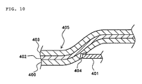
- Figure 10 schematically shows the state of the heat fusion layer damaged by the corner of the joining portion of the positive and negative electrode extending portion.
- reference numeral 400 denotes a heat fusion layer
- reference numeral 401 denotes a joining portion of the positive electrode extending portion
- reference numeral 402 denotes a metal layer
- reference numeral 403 denotes a protection layer
- reference numeral 404 denotes the flaw left in heat fusion layer 400.
- the counterpart laminate film which is heat-fused to laminate film 405 configured by heat fusion layer 400, metal layer 402, and protection layer 403, is not shown.
- the above described damage in the heat fusion layer during the manufacturing process cannot be sufficiently avoided only by providing an insulating spacer as disclosed in the above described pamphlet or other protection member made of resin between the joining portion of the positive and negative electrode extending portions, and the heat fusion layer. That is, in the case where the protection member made of resin has a melting point equal to or higher than that of the heat fusion layer, when the heat fusion layer is softened so as to be able to be heat-fused, the protection member has a stiffness equal to or higher than that of the heat fusion layer. Therefore, when the protection member is brought into contact with the softened heat fusion layer, the heat fusion layer is damaged similarly to the case where the joining portion of positive and negative electrode extending portions are brought into contact with the heat fusion layer.
- PP generally used as the heat fusion layer has a melting point of 140°C to 150°C. Therefore, in the case where the heat fusion layer is formed of PP, when the protection member is formed of a material having a melting point of 140°C to 150°C, or higher, the heat fusion layer is, on the contrary, damaged by the protection member.
- a film-packaged electric device includes: an electric device element configured such that a plurality of positive and negative electrode extending portions led out from a plurality of positive and negative electrode plates alternately laminated via separators are collectively joined to a positive or negative lead, respectively; and a package film configured such that at least a heat fusion layer and a metal layer are laminated with each other, to surround the electric device element with the heat fusion layer facing inward, and that the facing heat fusion layers are heat fused to each other.
- the film-packaged electric device is characterized in that a protection member is arranged at least between each of joining portions of the positive and negative electrode extending portions which are respectively joined to the positive and negative electrode leads, and one of the facing heat fusion layers, and in that the melting point of the protection member is lower than the melting point of the heat fusion layer.
- the heat fusion layer of the package film is not damaged by the joining portion of the positive electrode extending portion and the negative electrode extending portion. Further, even if the protection member is brought into contact with the heat fusion layer softened by heating at the time when the facing heat fusion layers are heat-fused to each other, the protection member is more softened than the heat fusion layer, and hence the heat fusion layer is not damaged by the protection member.
- a protection member having a melting point lower than that of the heat fusion layer may also be arranged between the positive and negative electrode leads and the other of the facing heat fusion layers. According to such configuration, it is possible to prevent the heat fusion layer from being damaged by the positive and negative electrode leads, and also possible to prevent the heat fusion layer from being damaged by the protection member.
- the protection member may be configured to have an upper surface portion arranged between the joining portion and one of the facing heat fusion layers, a lower surface portion arranged between the positive electrode lead or the negative electrode lead and the other of the facing heat fusion layers, and a connecting portion for connecting the upper surface portion and the lower surface portion, and may be configured such that an opening portion in which the positive electrode lead or the negative electrode lead can be inserted is formed in the connecting portion.
- the positive electrode lead or the negative electrode lead is made to pass through the opening portion, whereby the upper surface portion can be arranged between the joining portion and the heat fusion portion, and whereby the lower surface portion can be arranged between the positive electrode lead or the negative electrode lead and the heat fusion layer.
- the protection member is easily mounted, and the possibility of the occurrence of a failure, such as a positional deviation, is also reduced, as compared with the case where the protection member arranged between the joining portion and the heat fusion layer is separated from the protection member arranged between the positive electrode lead or the negative electrode lead and the heat fusion layer.
- the protection member having such configuration can be obtained, for example, in such a way that one of the surfaces of a sheet material or a film material which is folded into two portions, is used as the upper surface portion, that the other of the surfaces is used as the lower surface portion, and that the folded-back portion is used as the connecting portion.
- the protection member can also be three-dimensionally formed in correspondence with the shape of the positive electrode extending portion and the negative electrode extending portion.
- the protection member is formed into a bag shape having a substantially triangular cross section by making the upper surface portion and the lower surface portion come closer to each other as they approach the opening portion.
- the protection member is three-dimensionally formed, it is preferred that the upper surface portion and the lower surface portion are integrally connected by a side surface portion.
- the protection member may also be formed into a ring shape which can be made to cover each of the joining portions of the positive electrode extending portion and the negative electrode extending portion.
- the protection member can be made deformable according to the shape of the positive electrode extending portion and the negative electrode extending portion by being formed of an elastic material. Further, in the case where the protection member has elasticity, the protection member can be fixed to a predetermined position due to its elastic restoring force by making the protection member have a size equal to or slightly smaller than the size of the member covered by the protection member. Of course, the protection member can also be three-dimensionally formed by an elastic material. In the case where the protection member is formed to have elasticity, it is preferable to form the protection member using a foamed material. Further, the protection member may also be configured such that only a part of the protection member has elasticity. In the case where only a part of the protection member is made capable of expanding and contracting, it is preferred that the central portion of the protection member be formed of an elastic material, and that the corner portion of the protection member be formed of a non-elastic material.
- the protection member can also be formed into a frame shape which can be made to cover the peripheral portion of the electric device element, and which is configured such that a first opening portion into which the positive electrode lead can be inserted is formed in one side of a pair of sides that face each other, that a second opening portion into which the negative electrode lead can be inserted is formed in the other side of a pair of sides that face each other, that the side in which the first opening portion is formed is arranged between the joining portion of the positive electrode extending portion and the heat fusion layer, and that the side in which the second opening portion is formed is arranged between the joining portion of the negative electrode extending portion and the heat fusion layer.
- the respective materials are not limited in particular as long as the protection member has a melting point lower than that of the heat fusion layer.
- the protection member be formed of polyethylene, and that the heat fusion layer be formed of polypropylene.
- An object of the present invention is to provide a film-packaged electric device provided with a protection member for protecting a heat fusion layer of an outer package film surrounding an electric device element.
- the film-packaged electric device according to the present exemplary embodiment is a film-packaged battery in which a battery element is surrounded by a film-like package.
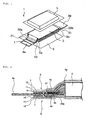
- FIG 1 is an exploded perspective view of the film-packaged battery according to the present exemplary embodiment.
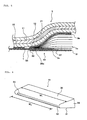
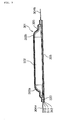
- Figure 2 is a partially omitted enlarged sectional view of the film-packaged battery.
- Film-packaged battery 1 includes battery element 2 having positive electrode extending portion 2a and negative electrode extending portion 2b, a package in which battery element 2 is stored together with electrolytic solution (not shown); positive electrode lead 3a connected to positive electrode extending portion 2a, negative electrode lead 3b connected to negative electrode extending portion 2b, and protection members 4a and 4a'.
- the package is configured by two laminate films 5 and 6. Note that protection members 4a and 4a' are not shown in Figure 1 .
- Battery element 2 is configured by separators and a plurality of positive electrode plates and negative electrode plates which are alternately laminated via the separators.
- each of the positive electrode plates is an aluminum foil coated with positive electrode material.
- Each of the negative electrode plates is a copper foil coated with negative electrode material. Portions (uncoated portions) of the respective foils, which portions are not coated with the electrode materials, are led out to the outside of the lamination area, so as to configure positive and negative electrode extending portions 2a and 2b.
- respective positive electrode extending portions 2a are collectively joined to a rear portion of positive electrode lead 3a by ultrasonic welding.
- Respective negative electrode extending portions 2b are collectively joined to a rear portion of negative electrode lead 3b by ultrasonic welding.
- polypropylene is applied to the front and rear surfaces of each of positive electrode lead 3a and negative electrode lead 3b in a strip form, so that coating portions 7 are formed.
- coating portions 7 of positive and negative electrode leads 3a and 3b are formed at positions nearer to the front end of leads 3a and 3b than the positions at which positive and negative electrode extending portion 2a and 2b are joined to positive and negative electrode leads 3a and 3b.
- Two laminate films 5 and 6 configuring the package are made to sandwich both thickness directions of battery element 2 so as to thereby surround battery element 2.
- Each of laminate films 5 and 6 is configured by three layers of heat fusion layer 10, metal layer 11, and protection layer 12.
- heat fusion layer 10 is formed of PP (polypropylene)
- metal layer 11 is formed of aluminum
- protection layer 12 is formed of nylon or PET (polyethylene terephthalate).
- Respective laminate films 5 and 6 are made to surround battery element 2 with heat fusion layer 10 facing inward. Further, the facing peripheral portions of heat fusion layers 10 of respective laminate films 5 and 6 are hermetically heat-fused to each other. Further, the areas of the peripheral portions of heat fusion layers 10 of respective laminate films 5 and 6, which face positive and negative electrode leads 3a and 3b, are heat-fused to coating layers 7 formed on respective leads 3a and 3b.
- Protection member 4a is provided between joining portions 20a and 20b of positive and negative electrode extending portions 2a and 2b, and laminate film 5 (heat fusion layer 10). Further, protection member 4a' is provided between positive and negative electrode leads 3a and 3b, and laminate film 6 (heat fusion layer 10). Note that in Figure 2 , there are only shown protection member 4a provided between joining portion 10a of positive electrode extending portion 2a and laminate film 5, and protection member 4a provided between positive electrode lead 3a and laminate film 6. However, protection member arranged on the side of positive electrode and protection member arranged on the side of negative electrode have the same configuration and the same operation effect. Therefore, here, protection members 4a and 4a' shown in the figure are taken as an example, and the configuration and operation effect of these are described.
- Each of protection members 4a and 4a' is a film or a sheet made of resin (PE: polyethylene in the present exemplary embodiment) having a melting point lower than that of heat fusion layer 10.
- the thickness of each of protection members 4a and 4a' is about 100 ⁇ m.
- Protection member 4a has a shape and size that are sufficient for covering joining portion 20a of positive electrode extending portions 2a, which joining portion is collectively welded to positive electrode lead 3a, or sufficient for covering at least corners 21 of joining portion 20a.
- protection member 4a' has a shape and size that are sufficient for covering the rear portion of positive electrode lead 3a, or sufficient for covering at least rear corner portions 22 of positive electrode lead 3a.
- protection members 4a and 4a' have the same shape and size.
- Protection members 4a and 4a' play a role of protecting heat fusion layers 10 of laminate films 5 and 6 at the time when heat fusion layers 10 are heat-fused to each other.
- protection member 4a is provided between heat fusion layer 10 of laminate film 5 and joining portion 20a, or at least between corner 21 of joining portion 20a and heat fusion layer 10, so as to prevent heat fusion layer 10 from being damaged by corner 21.
- protection member 4a' is provided between heat fusion layer 10 of laminate film 6 and positive electrode lead 3a, or at least between rear corner portion 22 of lead 3a and heat fusion layer 10, so as to prevent heat fusion layer 10 from being damaged by rear corner portion 22.
- laminate films 5 and 6 are arranged so as to sandwich battery element 2 from both thickness directions of battery element 2. Then, peripheral portions of laminate films 5 and 6 are heated by a heater, so that the facing peripheral portions of heat fusion layers 10 are heat-fused to each other, and heat fusion layer 10 is heat-fused to coating layer 7. At this time, when corner 21 of joining portion 20a or rear corner portion 22 of positive electrode lead 3a is brought into contact with heat fusion layer 10 softened by heating, heat fusion layer 10 is damaged. However, it is obvious from the above description, Figure 2 and the like, that such damage is prevented by protection members 4a and 4a'.
- protection members 4a and 4a' are formed of polyethylene having a melting point lower than that of heat fusion layer 10. This has the following technical significance. That is, in order to enable heat fusion layers 10 made of polypropylene to be heat-fused to each other, heat fusion layers 10 need to be heated to 140°C to 150°C. On the other hand, protection members 4a and 4a' made of polyethylene have a melting point of about 120°C. Therefore, before heat fusion layer 10 is heated to be softened, protection members 4a and 4a' are sufficiently softened.
- FIG 4 is a perspective view showing a modification of the protection member.
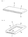
- Protection member 4b shown in Figure 4 is formed by folding, into two portions, a sheet material or a film material made of a material (polyethylene in the present exemplary embodiment) having a melting point lower than that of heat fusion layer 10.
- Protection member 4b is integrally formed by upper surface portion 30 covering positive and negative electrode extending portions 2a and 2b ( Figure 1 ), lower surface portion 31 covering rear portions of positive and negative electrode leads 3a and 3b ( Figure 1 ), and connecting portion 32 for connecting upper surface portion 30 and lower surface portion 31. Further, slit 33 through which positive and negative electrode leads 3a and 3b can be made to pass, is formed in connecting portion 32. Protection member 4b is arranged on both the positive electrode side and the negative electrode side.
- protection member 4b arranged on the positive electrode side and protection member 4b arranged on the negative electrode side have the same configuration and operation effects. Therefore, the configuration and operation effect of protection member 4b will be described by taking protection member 4b arranged on the positive electrode side as an example.
- protection member 4b As shown in Figure 5 , positive electrode lead 3a is made to pass through slit 33, and upper surface portion 30 is made to cover positive electrode extending portion 2a, and lower surface portion 31 is made to cover the rear portion of positive electrode lead 2a. Thereby, at least corner 21 of joining portion 20a and rear corner portion 22 of positive electrode lead 3a are covered by protection member 4b, so as to prevent heat fusion layer 10 from being damaged by corner 21 and rear corner portion 22.
- protection member 4b shown in Figure 4 is also formed of polyethylene having a melting point lower than that of heat fusion layer 10. Thus, there is no possibility that heat fusion layer 10 will be damaged by protection member 4b.
- laminate film 6 is also not shown in Figure 5 .
- the width (W 1 ) of upper surface portion 30 is formed to be slightly larger than the width of positive electrode extending portion 2a so that upper surface portion 30 covers positive electrode extending portion 2a as a whole in the width direction of positive electrode extending portion 2a.
- the width of positive electrode extending portion 2a is 66.0 mm
- the width (W 1 ) of upper surface portion 30 is 66.5 mm.
- upper surface portion 30 and lower surface portion 31 are made to have the same shape and size. However, upper surface portion 30 and lower surface portion 31 need not necessarily have the same shape and size.
- slit 33 has a shape and size so as to enable positive electrode lead 3a to be inserted therein.
- protection member 4b is inserted near the inner side of coating portion 7 formed on positive electrode lead 3a (see Figure 5 ). Therefore, the width (W 2 ) of slit 33 is formed to be slightly larger than the width of coating portion 7 so as to enable coating portion 7 to pass through slit 33.
- the width of coating portion 7 is 46.0 mm, while the width (W 2 ) of slit 33 is 46.5 mm.
- protection member 4b is formed of a material (for example, foamed material) having elasticity, it is possible to expand the width of slit 33 to some extent at the time when protection member 4b is mounted. Therefore, in the case where protection member 4b has elasticity, the width of slit 33 (W 2 ) may be set to be the same as or smaller than the width of coating portion 7.
- FIG. 6 is a perspective view showing another modification of the protection member.
- Protection member 4c shown in Figure 6 has a three-dimensional bag form in which upper surface portion 30 and lower surface portion 31 of protection member 4b shown in Figure 4 are integrally connected with each other by side surface portions 34.
- the mounting method and mounting state of protection member 4c shown in Figure 6 are the same as those of protection member 4b shown in Figure 4 , and hence a duplicated explanation will be omitted.
- protection member 4c shown in Figure 6 not only the upper and lower surfaces of positive and negative electrode extending portions 2a and 2b and of positive and negative electrode leads 3a and 3b but also the side surfaces of positive and negative electrode extending portions 2a and 2b and of positive and negative electrode leads 3a and 3b are covered by protection member 4c (specifically by side surface portions 34 of protection member 4c). Therefore, it is also possible to prevent heat fusion layer 10 from being damaged by the side surfaces of positive and negative electrode extending portions 2a and 2b and of positive and negative electrode leads 3a and 3b, and by the corners of the electrode extending portions and the electrode leads.
- the cross sectional shape of protection member 4c shown in Figure 6 is formed into a substantially triangular shape in correspondence with positive and negative electrode extending portions 2a and 2b, the thickness of which is gradually reduced in the direction away from the positive and negative electrode plates (see Figure 3 and Figure 5 ). Specifically, upper surface portion 30 and lower surface portion 31 are made to come closer to each other as they approach slit 33. However, in the case where protection member 4c has elasticity so as to be able to follow the above described form of positive and negative electrode extending portions 2a and 2b, it is not necessary to make the cross sectional shape of protection member 4a correspond to the form of positive and negative electrode extending portions 2a and 2b.
- FIG. 7 is a perspective view showing another modification of the protection member.
- Protection member 4d shown in the figure is obtained by forming a sheet material or a film material made of a material (polyethylene in the present exemplary embodiment) having a melting point lower than that of heat fusion layer 10 into a flat ring shape which can be made to cover the outside of each of joining portions 20a and 20b of positive and negative electrode extending portion 2a and 2b, and the outside of positive and negative electrode leads 3a and 3b. Protection member 4d is made to cover joining portions 20a and 20b, and positive and negative electrode leads 3a and 3b from the front end side of positive and negative electrode leads 3a and 3b.
- protection member 4d is made to cover joining portions 20a and 20b, while lower surface 36 is made to cover positive and negative electrode leads 3a and 3b. Thereby, at least corner 21 of joining portions 20a and 20b, and rear corner portion 22 of positive and negative electrode leads 3a and 3b are prevented from being brought into direct contact with heat fusion layers 10.
- protection member 4d is formed of an elastic material, and of protection member 4d which is made to cover joining portions 20a and 20b and positive and negative electrode leads 3a and 3b as described above, it is fixed to joining portions 20a and 20b and positive and negative electrode leads 3a and 3b by elastic restoring force of protection member 4d.
- the inner diameter of protection member 4d is set to be equal to or smaller than the outer diameter of joining portions 20a and 20b, and the outer diameter of positive and negative electrode leads 3a and 3b.
- protection member 4d is temporarily expanded to increase the inner diameter thereof.
- protection member 4d is made expandable and contractible, not only protection member 4d as a whole may be made expandable and contractible, but also a part of protection member 4d may also be made expandable and contractible. Further, in the case where a part of protection member 4d is made expandable and contractible, it is preferable to make the central portions of upper surface 35 and lower surface 36 expandable and contractible.
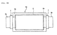
- Figure 8A is a perspective view showing another modification of the protection member.
- Protection member 4e shown in Figure 8A is formed into a substantially rectangular frame shape which can be made to cover the peripheral portion of battery element 2 (see Figure 1 ).
- Slits 33 enabling positive and negative electrode leads 3a and 3b to pass therethrough are formed in the short side portions 40a and 40b of protection member 4e that face each other.
- positive and negative electrode leads 3a and 3b are made to pass through slits 33 of protection member 4e, respectively.
- protection member 4e is also formed of a material (polyethylene in the present exemplary embodiment) having a melting point lower than that of heat fusion layer 10, and hence heat fusion layer 10 will not be damaged by protection member 4e.
- the protection member is brought into close contact with the positive and negative electrode extending portions or/and the positive and negative electrode leads.
- it is sufficient to provide the protection member between the heat fusion layer, and the positive and negative electrode extending portions or/and the positive and negative electrode leads, only so as to prevent the heat fusion layer from being damaged. Therefore, the protection member does not necessarily need to be brought into close contact with the positive and negative electrode extending portions or/and the positive and negative electrode leads.
- the positive and negative electrode extending portions have substantially the same width as the width of the positive and negative electrode leads.
- the width of the positive and negative electrode extending portions may be narrower or wider than the width of the positive and negative electrode leads.
- the size and shape of the protection member are suitably changed so that the positive and negative electrode extending portions or/and the positive and negative electrode leads are properly covered by the protection member.
- Al, Cu, Ni, Ti and Fe, phosphor bronze, brass, stainless steel, and the like, can be used as the material of the positive and negative electrode leads.
- the positive and negative electrode leads may be subjected to annealing processing as required.
- As for the thickness of the positive and negative electrode leads a thickness of 0.08 to 1.0 mm is preferred.
- the positive and negative electrode leads are also preferred to make at least a portion of the positive and negative electrode leads, which portion is brought into close contact with the package, subjected to surface treatment for improving the adhesiveness property with the package.
- surface treatment of this type there are listed treatments, such as a surface roughening treatment by chemical etching or the like, a corrosion resistant film preparation treatment by a film made of partially aminated phenolic polymer, phosphoric acid compound and titanium compound, a corrosion resistant film preparation treatment by a zinc phosphate based film, or the like, a surface treatment by a titanium based coupling agent, an aluminate based coupling agent, or the like.
- the coating layer formed on the positive and negative electrode leads there can be used, for example, acid denaturated polypropylene, acid denaturated polyethylene, acid denaturated poly (ethylenepropylene) copolymer, ionomer, and the like.
- the package is not limited in particular as long as it has flexibility and is capable of covering the battery element so as to prevent an electrolytic solution from leaking.
- a laminate film formed by laminating a metal layer and a heat fusion layer is preferably used in particular as the package.
- As a laminate film of this kind it is possible to use, for example, a laminate film in which a heat fusion layer having a thickness of 3 ⁇ m to 200 ⁇ m is formed on a metal foil having a thickness of 10 ⁇ m to 100 ⁇ m.
- As a material of the metal foil it is possible to use Al, Ti, a Ti based alloy, Fe, stainless steel, an Mg based alloy, and the like.
- the heat fusion layer it is possible to use polypropylene, polyethylene, acid-modified products of polypropylene or polyethylene, polyphenylene sulfide, polyester such as polyethylene terephthalate, polyamide, ethylene vinyl acetate copolymer, and the like.
- polyester such as polyethylene terephthalate
- polyamide such as nylon
- polyester such as PET and polyethylenenaphthalate (PEN)
- PEN polyethylenenaphthalate
- the positive electrode plate is not limited in particular, as long as it absorbs positive ions or emits negative ions at the time of discharge.
- As a material of the positive electrode plate it is possible to use any of known positive electrode materials as listed below under (1) to (3).
- the positive electrode plate can be formed by mixing a positive electrode active material (not shown) with a suitable binder and a functional material.
- a positive electrode active material (not shown)
- a suitable binder there are listed halogen-containing polymer such as polyvinylidene fluoride, and the like.
- the functional material there are listed acetylene black for securing electron conductivity, conductive polymers, such as, polypyrrole, and poly aniline, polymer electrolyte for securing ion conductivity, a composite of these materials, and the like.
- the negative electrode plate is not limited in particular as long as it is capable of storing and releasing cation.
- As a material of the negative electrode plate it is possible to use any of known negative electrode materials as listed below under (1) to (3).
- the electrolytic solution impregnated in the battery element there is listed, for example, a product obtained in such a way that a salt which is made of cation of an alkali metal, such as Li, K and Na, and which is made of anion of a compound containing halogen such as ClO 4 - , BF 4 - , PF 6 - , CF 3 SO 3 - , (CF 3 SO 2 ) 2 N - , (C 2 F 5 SO 2 ) 2 N - , (CF 3 SO 2 ) 3 C - , and (C 2 F 5 SO 2 ) 3 C - is made to dissolve in a highly polar basic solvent which can be used as an electrolytic solution of a secondary battery, such as ethylene carbonate, propylene carbonate, dimethyl carbonate, diethyl carbonate, methylethyl carbonate, ⁇ -butyrolactone, N, N'-dimethylformamide, dimethyl sulfoxide, N-methylpyrrolidon
- a solvent and an electrolyte salt which are made of these basic solvents, or to together use the plurality of the solvents and the electrolyte salts.
- a gel electrolyte polymer gel containing an electrolytic solution.
- the above described materials are examples in the case where the electric device element is a lithium ion secondary battery.
- the electrical device element configuring the film-packaged electric device according to the present invention also includes a lead battery, a nickel-cadmium battery, and a nickel hydride battery. Further, the electrical device element also includes capacitor elements, such as an electric double layer capacitor and an electrolytic capacitor.
Landscapes
- Chemical & Material Sciences (AREA)
- Chemical Kinetics & Catalysis (AREA)
- Electrochemistry (AREA)
- General Chemical & Material Sciences (AREA)
- Engineering & Computer Science (AREA)
- Manufacturing & Machinery (AREA)
- Inorganic Chemistry (AREA)
- Sealing Battery Cases Or Jackets (AREA)
- Connection Of Batteries Or Terminals (AREA)
- Electric Double-Layer Capacitors Or The Like (AREA)
Applications Claiming Priority (2)
| Application Number | Priority Date | Filing Date | Title |
|---|---|---|---|
| JP2006067496 | 2006-03-13 | ||
| PCT/JP2007/054319 WO2007105541A1 (fr) | 2006-03-13 | 2007-03-06 | Dispositif electrique avec capot de film exterieur |
Publications (3)
| Publication Number | Publication Date |
|---|---|
| EP2006935A1 true EP2006935A1 (fr) | 2008-12-24 |
| EP2006935A4 EP2006935A4 (fr) | 2011-04-13 |
| EP2006935B1 EP2006935B1 (fr) | 2012-09-26 |
Family
ID=38509376
Family Applications (1)
| Application Number | Title | Priority Date | Filing Date |
|---|---|---|---|
| EP07737866A Not-in-force EP2006935B1 (fr) | 2006-03-13 | 2007-03-06 | Dispositif electrique avec revêtement de film exterieur |
Country Status (6)
| Country | Link |
|---|---|
| US (2) | US8383261B2 (fr) |
| EP (1) | EP2006935B1 (fr) |
| JP (2) | JP5169820B2 (fr) |
| KR (1) | KR101005448B1 (fr) |
| CN (1) | CN101405894B (fr) |
| WO (1) | WO2007105541A1 (fr) |
Cited By (6)
| Publication number | Priority date | Publication date | Assignee | Title |
|---|---|---|---|---|
| WO2013108118A1 (fr) * | 2012-01-20 | 2013-07-25 | Miljobil Grenland As | Cassette à cellules améliorées avec une structure de relaxation de contrainte de languettes de cellules incorporée |
| EP2709187A1 (fr) * | 2012-09-14 | 2014-03-19 | Kabushiki Kaisha Toshiba | Batterie résistant aux vibrations et chocs |
| JP2014239053A (ja) * | 2008-03-14 | 2014-12-18 | 日本電気株式会社 | フィルム外装電気デバイス |
| EP2383818A4 (fr) * | 2009-01-13 | 2015-03-11 | Showa Denko Packaging Co Ltd | Dispositif électrochimique et son procédé de fabrication |
| EP3712977A1 (fr) * | 2019-03-22 | 2020-09-23 | Ningde Amperex Technology Ltd. | Batterie et dispositif l'utilisant |
| US11437673B2 (en) | 2019-03-22 | 2022-09-06 | Ningde Amperex Technology Ltd | Battery and device using the same |
Families Citing this family (48)
| Publication number | Priority date | Publication date | Assignee | Title |
|---|---|---|---|---|
| JP5197103B2 (ja) * | 2008-03-31 | 2013-05-15 | 三洋電機株式会社 | 積層式電池、積層電極体群作製冶具及びその冶具を用いた積層式電池の製造方法 |
| US20090197160A1 (en) * | 2008-01-31 | 2009-08-06 | Sanyo Electric Co., Ltd. | Stack type battery |
| JP5252937B2 (ja) * | 2008-01-31 | 2013-07-31 | 三洋電機株式会社 | 積層式電池及びその製造方法 |
| JP4835742B2 (ja) * | 2009-02-20 | 2011-12-14 | ソニー株式会社 | 電池および電池パック |
| JP5355281B2 (ja) * | 2009-07-30 | 2013-11-27 | 日清紡ホールディングス株式会社 | 電気二重層キャパシタ |
| DE102009035495A1 (de) | 2009-07-31 | 2011-02-03 | Daimler Ag | Batterie mit einem Stapel von bipolaren Batterieeinzelzellen |
| US8974952B2 (en) * | 2009-10-13 | 2015-03-10 | Samsung Sdi Co., Ltd. | Rechargeable battery |
| WO2011070918A1 (fr) * | 2009-12-07 | 2011-06-16 | 株式会社 村田製作所 | Dispositif de stockage d'électricité et son procédé de fabrication |
| DE102010026093A1 (de) * | 2010-07-05 | 2012-01-05 | Li-Tec Battery Gmbh | Galvanische Zelle |
| JP5676172B2 (ja) * | 2010-08-03 | 2015-02-25 | Necエナジーデバイス株式会社 | ラミネートフィルム外装積層型電池の製造方法 |
| JP5548827B2 (ja) * | 2010-08-09 | 2014-07-16 | エルジー・ケム・リミテッド | 安全性が向上した二次バッテリー |
| JP5842340B2 (ja) * | 2011-02-21 | 2016-01-13 | 大日本印刷株式会社 | 電気化学セル用包装材料およびその製造方法 |
| JP5667537B2 (ja) * | 2011-08-22 | 2015-02-12 | Jmエナジー株式会社 | 蓄電デバイス |
| KR101192619B1 (ko) * | 2012-03-23 | 2012-10-18 | 주식회사 엘지화학 | 전지케이스 |
| US9716253B2 (en) | 2012-03-23 | 2017-07-25 | Lg Chem, Ltd. | Battery case for secondary battery |
| JP5884703B2 (ja) * | 2012-10-04 | 2016-03-15 | 株式会社デンソー | 非水電解質二次電池 |
| KR101500233B1 (ko) * | 2013-12-19 | 2015-03-09 | 현대자동차주식회사 | 차량의 고전압배터리 |
| WO2015173686A1 (fr) * | 2014-05-16 | 2015-11-19 | Semiconductor Energy Laboratory Co., Ltd. | Dispositif électronique avec batterie secondaire |
| KR102177505B1 (ko) * | 2014-06-17 | 2020-11-11 | 삼성에스디아이 주식회사 | 이차 전지 |
| JP6191588B2 (ja) * | 2014-12-09 | 2017-09-06 | トヨタ自動車株式会社 | 二次電池の製造方法 |
| US10770692B1 (en) * | 2015-08-11 | 2020-09-08 | Google Llc | Solid state batteries made on a mobile computing device |
| JP6576779B2 (ja) * | 2015-10-02 | 2019-09-18 | 昭和電工パッケージング株式会社 | ラミネート外装材 |
| CN105514307A (zh) * | 2016-01-22 | 2016-04-20 | 宁德新能源科技有限公司 | 一种锂离子电池封装外壳及含有该封装外壳的锂离子电池 |
| WO2017145212A1 (fr) * | 2016-02-24 | 2017-08-31 | パナソニックIpマネジメント株式会社 | Batterie mince |
| JP6697323B2 (ja) * | 2016-05-24 | 2020-05-20 | 株式会社エンビジョンAescジャパン | リチウムイオン二次電池 |
| JP6778545B2 (ja) * | 2016-08-09 | 2020-11-04 | 株式会社東芝 | 組電池 |
| KR102227808B1 (ko) * | 2017-03-31 | 2021-03-15 | 주식회사 엘지화학 | 이차전지 및 그의 제조방법 |
| JP6344510B2 (ja) * | 2017-06-19 | 2018-06-20 | トヨタ自動車株式会社 | 二次電池 |
| CN110998914A (zh) * | 2017-08-03 | 2020-04-10 | 艾利电力能源有限公司 | 密闭型电池、电池组及密闭型电池的制造方法 |
| JP7213455B2 (ja) * | 2017-12-05 | 2023-01-27 | パナソニックIpマネジメント株式会社 | 二次電池、絶縁部材及び正極リード |
| JP7058526B2 (ja) * | 2018-03-15 | 2022-04-22 | マクセル株式会社 | 電気化学素子 |
| JP2020053119A (ja) * | 2018-09-21 | 2020-04-02 | 積水化学工業株式会社 | 蓄電素子、蓄電素子の製造方法 |
| JP7194331B2 (ja) * | 2019-02-12 | 2022-12-22 | トヨタ自動車株式会社 | ラミネート型電池 |
| JP7212547B2 (ja) * | 2019-02-28 | 2023-01-25 | 古河電池株式会社 | ラミネート外装電池 |
| JP2020170639A (ja) * | 2019-04-03 | 2020-10-15 | 積水化学工業株式会社 | 積層型電池 |
| US11355802B2 (en) * | 2019-04-26 | 2022-06-07 | Toyota Jidosha Kabushiki Kaisha | Secondary battery having improved manufacturability and performance |
| KR102809759B1 (ko) * | 2019-10-14 | 2025-05-16 | 주식회사 엘지에너지솔루션 | 배터리 셀, 이러한 배터리 셀을 포함하는 배터리 모듈 및 이러한 배터리 모듈을 포함하는 배터리 팩 |
| CN212587691U (zh) * | 2020-05-18 | 2021-02-23 | 比亚迪股份有限公司 | 一种电芯组件、电池、电池包及汽车 |
| KR102856921B1 (ko) | 2021-01-28 | 2025-09-09 | 주식회사 엘지에너지솔루션 | 외형고정틀이 구비된 전극조립체 및 이를 포함하는 리튬 이차전지 |
| JP7548128B2 (ja) * | 2021-06-01 | 2024-09-10 | トヨタ自動車株式会社 | 外装体および電池 |
| US20230170590A1 (en) * | 2021-09-01 | 2023-06-01 | Lg Energy Solution, Ltd. | Battery Cell, and Battery Module, Battery Pack and Vehicle Including the Same |
| KR20230039939A (ko) * | 2021-09-15 | 2023-03-22 | 에스케이온 주식회사 | 이차전지 및 이의 제조방법 |
| JP7735547B2 (ja) * | 2022-03-11 | 2025-09-08 | エルジー エナジー ソリューション リミテッド | バッテリーセル、バッテリーモジュール、バッテリーパック及び当該バッテリーパックを含む自動車 |
| JP7571757B2 (ja) * | 2022-03-18 | 2024-10-23 | トヨタ自動車株式会社 | 電池の製造方法及び電池 |
| CN115020934B (zh) * | 2022-06-28 | 2026-01-27 | 中创新航科技集团股份有限公司 | 电池及电池的制造方法 |
| CN115347291B (zh) * | 2022-10-13 | 2023-03-24 | 宁德新能源科技有限公司 | 电化学装置和电子装置 |
| JP7782473B2 (ja) * | 2023-01-10 | 2025-12-09 | トヨタ自動車株式会社 | ラミネート型電池、電池スタック及びラミネート型電池の製造方法 |
| KR20250092873A (ko) * | 2023-12-15 | 2025-06-24 | 삼성에스디아이 주식회사 | 전고체 이차 전지 |
Family Cites Families (10)
| Publication number | Priority date | Publication date | Assignee | Title |
|---|---|---|---|---|
| CN1180506C (zh) | 1999-03-26 | 2004-12-15 | 松下电器产业株式会社 | 叠合片封装型电池 |
| US7048822B2 (en) * | 1999-12-17 | 2006-05-23 | Dai Nippon Printing Co., Ltd. | Packaging material for polymer cell and method for producing the same |
| JP4951810B2 (ja) * | 2000-12-08 | 2012-06-13 | パナソニック株式会社 | 扁平電池 |
| JP2002298825A (ja) * | 2001-03-29 | 2002-10-11 | Tdk Corp | 電気化学デバイスの製造方法、および電気化学デバイス |
| JP2003109557A (ja) * | 2001-09-28 | 2003-04-11 | Mitsubishi Electric Corp | 非水電解質電池及びその製造方法 |
| DE10225041B4 (de) * | 2002-06-06 | 2014-05-08 | Varta Microbattery Gmbh | Galvanisches Element |
| JP4894129B2 (ja) | 2003-10-10 | 2012-03-14 | 日産自動車株式会社 | 薄型電池及び組電池 |
| WO2005086258A1 (fr) * | 2004-03-09 | 2005-09-15 | Nec Lamilion Energy, Ltd. | Dispostiif electrique enrobe en couche mince et organe de couverutre collecteur pour le dispositif electrique enrobe en couche mince: |
| WO2005086254A1 (fr) | 2004-03-10 | 2005-09-15 | Canon Kabushiki Kaisha | Transistor à effet de champ, procédé de fabrication de celui-ci est procédé de fabrication d'un élément stratifié |
| JP4424053B2 (ja) | 2004-04-28 | 2010-03-03 | トヨタ自動車株式会社 | ラミネート型二次電池、およびその組電池 |
-
2007
- 2007-03-06 KR KR1020087025010A patent/KR101005448B1/ko not_active Expired - Fee Related
- 2007-03-06 JP JP2008505070A patent/JP5169820B2/ja active Active
- 2007-03-06 EP EP07737866A patent/EP2006935B1/fr not_active Not-in-force
- 2007-03-06 CN CN2007800094100A patent/CN101405894B/zh not_active Expired - Fee Related
- 2007-03-06 WO PCT/JP2007/054319 patent/WO2007105541A1/fr not_active Ceased
- 2007-03-06 US US12/282,843 patent/US8383261B2/en active Active
-
2012
- 2012-11-07 JP JP2012245148A patent/JP5516697B2/ja active Active
- 2012-11-20 US US13/682,345 patent/US8741468B2/en active Active
Cited By (7)
| Publication number | Priority date | Publication date | Assignee | Title |
|---|---|---|---|---|
| JP2014239053A (ja) * | 2008-03-14 | 2014-12-18 | 日本電気株式会社 | フィルム外装電気デバイス |
| EP2383818A4 (fr) * | 2009-01-13 | 2015-03-11 | Showa Denko Packaging Co Ltd | Dispositif électrochimique et son procédé de fabrication |
| WO2013108118A1 (fr) * | 2012-01-20 | 2013-07-25 | Miljobil Grenland As | Cassette à cellules améliorées avec une structure de relaxation de contrainte de languettes de cellules incorporée |
| EP2709187A1 (fr) * | 2012-09-14 | 2014-03-19 | Kabushiki Kaisha Toshiba | Batterie résistant aux vibrations et chocs |
| US9614194B2 (en) | 2012-09-14 | 2017-04-04 | Kabushiki Kaisha Toshiba | Battery |
| EP3712977A1 (fr) * | 2019-03-22 | 2020-09-23 | Ningde Amperex Technology Ltd. | Batterie et dispositif l'utilisant |
| US11437673B2 (en) | 2019-03-22 | 2022-09-06 | Ningde Amperex Technology Ltd | Battery and device using the same |
Also Published As
| Publication number | Publication date |
|---|---|
| US20090263712A1 (en) | 2009-10-22 |
| EP2006935A4 (fr) | 2011-04-13 |
| CN101405894A (zh) | 2009-04-08 |
| CN101405894B (zh) | 2011-07-06 |
| JPWO2007105541A1 (ja) | 2009-07-30 |
| US8741468B2 (en) | 2014-06-03 |
| JP5169820B2 (ja) | 2013-03-27 |
| JP5516697B2 (ja) | 2014-06-11 |
| US8383261B2 (en) | 2013-02-26 |
| WO2007105541A1 (fr) | 2007-09-20 |
| KR20080102311A (ko) | 2008-11-24 |
| US20130078507A1 (en) | 2013-03-28 |
| KR101005448B1 (ko) | 2011-01-05 |
| EP2006935B1 (fr) | 2012-09-26 |
| JP2013041851A (ja) | 2013-02-28 |
Similar Documents
| Publication | Publication Date | Title |
|---|---|---|
| EP2006935B1 (fr) | Dispositif electrique avec revêtement de film exterieur | |
| US10516141B2 (en) | Power storage device and production method thereof | |
| KR101947837B1 (ko) | 탭 리드 및 그 제조 방법 | |
| JP3972205B2 (ja) | 積層型電池 | |
| KR102488346B1 (ko) | 조전지 | |
| EP1734596A1 (fr) | Dispostiif electrique enrobe en couche mince et organe de couverutre collecteur pour le dispositif electrique enrobe en couche mince: | |
| KR102611304B1 (ko) | 전기 화학 소자 | |
| KR101487092B1 (ko) | 이차전지용 파우치 및 이를 포함하는 이차전지 | |
| US20180158623A1 (en) | Method for manufacturing electrochemical device | |
| US20200251783A1 (en) | Secondary battery | |
| KR20160126870A (ko) | 축전 디바이스용 외장체 및 축전 디바이스 | |
| KR20140012601A (ko) | 이차전지 및 이를 포함하는 전기화학소자 | |
| US10158107B2 (en) | Battery comprising insulative films | |
| KR101484369B1 (ko) | 이차전지 및 이를 포함하는 전기화학소자 | |
| JP7194334B2 (ja) | ラミネート型二次電池および該二次電池を備える組電池 | |
| JP2020170667A (ja) | 積層型電池の製造方法および積層型電池 | |
| JP2019071259A (ja) | 蓄電素子、及び蓄電素子の製造方法 | |
| CN114914518B (zh) | 非水电解液二次电池 | |
| JP2021034187A (ja) | 積層型電池及び積層型電池の製造方法 | |
| JP7010904B2 (ja) | 蓄電素子の製造方法 | |
| WO2025253932A1 (fr) | Dispositif d'accumulation d'électricité | |
| CN118266129A (zh) | 二次电池 | |
| JP2021039833A (ja) | 蓄電素子及び蓄電素子の製造方法 | |
| HK1116926A1 (en) | Sheet-type secondary battery and manufacturing method therefor | |
| HK1116926B (en) | Sheet-type secondary battery and manufacturing method therefor |
Legal Events
| Date | Code | Title | Description |
|---|---|---|---|
| PUAI | Public reference made under article 153(3) epc to a published international application that has entered the european phase |
Free format text: ORIGINAL CODE: 0009012 |
|
| 17P | Request for examination filed |
Effective date: 20081007 |
|
| AK | Designated contracting states |
Kind code of ref document: A1 Designated state(s): DE FR IT |
|
| RBV | Designated contracting states (corrected) |
Designated state(s): DE FR IT |
|
| RBV | Designated contracting states (corrected) |
Designated state(s): DE FR IT |
|
| RBV | Designated contracting states (corrected) |
Designated state(s): DE FR IT |
|
| A4 | Supplementary search report drawn up and despatched |
Effective date: 20110311 |
|
| RIC1 | Information provided on ipc code assigned before grant |
Ipc: H01M 2/08 20060101ALI20110307BHEP Ipc: H01M 2/02 20060101ALI20110307BHEP Ipc: H01M 2/06 20060101AFI20071008BHEP Ipc: H01M 2/26 20060101ALI20110307BHEP |
|
| REG | Reference to a national code |
Ref country code: DE Ref legal event code: R079 Ref document number: 602007025713 Country of ref document: DE Free format text: PREVIOUS MAIN CLASS: H01M0002060000 Ipc: H01M0010040000 |
|
| RIC1 | Information provided on ipc code assigned before grant |
Ipc: H01M 2/06 20060101ALI20120228BHEP Ipc: H01M 2/08 20060101ALI20120228BHEP Ipc: H01M 2/26 20060101ALI20120228BHEP Ipc: H01M 10/04 20060101AFI20120228BHEP Ipc: H01M 2/02 20060101ALI20120228BHEP |
|
| RTI1 | Title (correction) |
Free format text: ELECTRIC DEVICE WITH OUTER FILM COVER |
|
| GRAP | Despatch of communication of intention to grant a patent |
Free format text: ORIGINAL CODE: EPIDOSNIGR1 |
|
| DAX | Request for extension of the european patent (deleted) | ||
| RIN1 | Information on inventor provided before grant (corrected) |
Inventor name: MIZUTA, MASATOMO Inventor name: NODA, SHUNJI |
|
| GRAS | Grant fee paid |
Free format text: ORIGINAL CODE: EPIDOSNIGR3 |
|
| GRAA | (expected) grant |
Free format text: ORIGINAL CODE: 0009210 |
|
| AK | Designated contracting states |
Kind code of ref document: B1 Designated state(s): DE FR IT |
|
| REG | Reference to a national code |
Ref country code: DE Ref legal event code: R096 Ref document number: 602007025713 Country of ref document: DE Effective date: 20121122 |
|
| PLBE | No opposition filed within time limit |
Free format text: ORIGINAL CODE: 0009261 |
|
| STAA | Information on the status of an ep patent application or granted ep patent |
Free format text: STATUS: NO OPPOSITION FILED WITHIN TIME LIMIT |
|
| 26N | No opposition filed |
Effective date: 20130627 |
|
| REG | Reference to a national code |
Ref country code: DE Ref legal event code: R097 Ref document number: 602007025713 Country of ref document: DE Effective date: 20130627 |
|
| REG | Reference to a national code |
Ref country code: FR Ref legal event code: PLFP Year of fee payment: 10 |
|
| PGFP | Annual fee paid to national office [announced via postgrant information from national office to epo] |
Ref country code: DE Payment date: 20160302 Year of fee payment: 10 |
|
| PGFP | Annual fee paid to national office [announced via postgrant information from national office to epo] |
Ref country code: FR Payment date: 20160208 Year of fee payment: 10 |
|
| PGFP | Annual fee paid to national office [announced via postgrant information from national office to epo] |
Ref country code: IT Payment date: 20160324 Year of fee payment: 10 |
|
| REG | Reference to a national code |
Ref country code: DE Ref legal event code: R119 Ref document number: 602007025713 Country of ref document: DE |
|
| REG | Reference to a national code |
Ref country code: FR Ref legal event code: ST Effective date: 20171130 |
|
| PG25 | Lapsed in a contracting state [announced via postgrant information from national office to epo] |
Ref country code: DE Free format text: LAPSE BECAUSE OF NON-PAYMENT OF DUE FEES Effective date: 20171003 Ref country code: FR Free format text: LAPSE BECAUSE OF NON-PAYMENT OF DUE FEES Effective date: 20170331 |
|
| PG25 | Lapsed in a contracting state [announced via postgrant information from national office to epo] |
Ref country code: IT Free format text: LAPSE BECAUSE OF NON-PAYMENT OF DUE FEES Effective date: 20170306 |