EP2007302B9 - Electrode plane - Google Patents
Electrode plane Download PDFInfo
- Publication number
- EP2007302B9 EP2007302B9 EP06704699A EP06704699A EP2007302B9 EP 2007302 B9 EP2007302 B9 EP 2007302B9 EP 06704699 A EP06704699 A EP 06704699A EP 06704699 A EP06704699 A EP 06704699A EP 2007302 B9 EP2007302 B9 EP 2007302B9
- Authority
- EP
- European Patent Office
- Prior art keywords
- electrode
- planar
- planar electrode
- extension sections
- along
- Prior art date
- Legal status (The legal status is an assumption and is not a legal conclusion. Google has not performed a legal analysis and makes no representation as to the accuracy of the status listed.)
- Expired - Lifetime
Links
Images


Classifications
-
- A—HUMAN NECESSITIES
- A61—MEDICAL OR VETERINARY SCIENCE; HYGIENE
- A61B—DIAGNOSIS; SURGERY; IDENTIFICATION
- A61B18/00—Surgical instruments, devices or methods for transferring non-mechanical forms of energy to or from the body
- A61B18/04—Surgical instruments, devices or methods for transferring non-mechanical forms of energy to or from the body by heating
- A61B18/12—Surgical instruments, devices or methods for transferring non-mechanical forms of energy to or from the body by heating by passing a current through the tissue to be heated, e.g. high-frequency current
- A61B18/14—Probes or electrodes therefor
- A61B18/16—Indifferent or passive electrodes for grounding
-
- A—HUMAN NECESSITIES
- A61—MEDICAL OR VETERINARY SCIENCE; HYGIENE
- A61N—ELECTROTHERAPY; MAGNETOTHERAPY; RADIATION THERAPY; ULTRASOUND THERAPY
- A61N1/00—Electrotherapy; Circuits therefor
- A61N1/02—Details
- A61N1/04—Electrodes
- A61N1/06—Electrodes for high-frequency therapy
Definitions
- the invention relates to a planar electrode, in particular a neutral electrode, for medical purposes with two equally large, along a linear insulating zone electrically separated electrode surfaces which adjoin one another directly along an inner edge portion.
- flat electrodes are understood to mean all medical electrodes for attachment to the skin.
- WO 0065993A is in Figure 5 a medical neutral electrode having two equal-sized semicircular electrode surfaces which face each other along an inner rectilinear edge portion and are separated by a line-shaped insulating zone.
- the two semicircular electrodes are surrounded by a ring-like extending around this, band-like electrode, which is completely electrically isolated from two electrode halves.
- Figure 3 This document shows an electrode in which a band-shaped extension of an electrode half extends around almost the entire remaining inner part of the interleaved electrode structure.
- monitoring devices In order to ensure the full-surface concerns of the neutral electrode, monitoring devices have been developed that perform resistance or symmetry measurements during the operation or between the individual treatment steps.
- the high-frequency generators in use usually have a Contact Quality Monitoring (CQM) device, which checks the correct and full-surface application of the neutral electrode on the skin of the patient regardless of the cutting current of the surgical apparatus.
- CQM Contact Quality Monitoring
- Prerequisite for this are two- or multi-part neutral electrodes, which allow a measurement of the impedance between the electrode parts. Since the skin resistance varies greatly from patient to patient, it is a clear statement whether the neutral electrode rests correctly or not often very difficult and it can lead to incorrect measurements.
- the sensitivity of the impedance monitoring can be increased.
- the line-shaped insulating zone is guided meandering over the entire electrode surface. An areal detachment of the electrode thus has an approximately proportional effect on the impedance measured by the CQM device.
- some high frequency generators have a symmetry test circuit, which determines a measurement of the leakage current of the electrode parts, whether a symmetrical current distribution is present or whether an electrode part leads to a higher proportion of current.
- a symmetrical current distribution through the neutral electrode can be promoted by means of a suitable design of the neutral electrode. As has been shown, it is not enough, as in the electrode according to DE 42 31 236 C2 To dimension the electrode parts with the same area, since the current consumption per unit area of the electrode is highly directional with respect to the surgical field and also to the orientation of the surrounding muscle tissue, which is known to the skilled person.
- the object of the invention is therefore to provide an aforementioned flat electrode, with the addition of a CQM proportionalization in addition also the achievement of symmetrical leakage currents in the application mode is achieved.
- this is achieved in that the two equal-sized electrode surfaces each have a band-shaped extension portion which surrounds the respective other electrode surface at least along an outer edge portion and is thereby separated by the extended insulating zone of the respectively surrounded electrode surface, and that the two outer edge portions essentially each extending from the one end of the inner edge portion of the respective other electrode surface around at least to the opposite other end of the inner edge portion.
- the two equal-sized electrode surfaces are semicircular at their opposite end of the inner portion of the line-shaped insulating zone, which end of each of the band-shaped extension portions is surrounded by the outer portions of the line-shaped insulating zone sickle-shaped.
- both a long Isolierpfad can be achieved by the electrode according to the invention, which allows high sensitivity of the CQM measurement as well as an electrode surface design can be chosen, which ensures a reliable symmetry measurement of the leakage currents during the operation, as well as in the edge regions disproportionate influence on the measurement result, the proportions of the electrode surface can be arranged the same size.
- the two centrally located electrode surfaces are surrounded by the extension sections of the respective other electrode surface.
- a relatively long insulating path and also a surface area distribution of the electrode surfaces that is symmetrical with respect to the edge regions is thereby possible.
- a simple structural design results when an inner portion of the line-shaped insulating zone and the adjoining inner edge portions of the two equal-sized electrode surfaces are rectilinear and extend along a minor axis of the planar electrode.
- rounded electrode shapes are advantageous which avoid smaller radii of curvature in the edge regions.
- a feature of the electrode according to the invention may be that the two electrode surfaces are formed twice symmetrical about an axis perpendicular to the plane of the planar electrode.
- terminal tabs may be disposed at one end of one of the extension portions of the area electrodes and a transition area between the other of the area electrodes and the other extension portion.
- connection of the electrode according to the invention can take place on one side, whereby the side opposite this side, which has no connections, is suitable for being oriented on the patient in the direction of the surgical field.
- terminal lugs extend on one side of the planar electrode in the imaginary extension of the inner portion along the minor axis.
- extension portions each extend in a lying along the minor axis corner region of the surface electrodes thereof, wherein the corner regions are equally spaced from a major axis of the planar electrode, and in that the extension sections extend around the other of the two electrode surfaces substantially to the vicinity of the corner region of the other electrode surface.
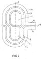
- Another embodiment of the invention in which there is an increased length of the insulating zone, may be that each along the major axis a projection of the band-shaped extension portions extends into the respective other electrode surface.
- the current density during use is relatively low, so that this zone can be used to provide connections for the electrode surfaces. This can be achieved in that connecting tabs are provided in the central region, which are connected to the electrode surfaces.
- a multiplication of the inventive principle which is within the scope of the invention, can be achieved, for example, that the guided around the other electrode surface extension sections are then returned to the area of the associated electrode surface and there, separated by the linear insulating zone, the other Surrounding extension sections.
- the proportion of current of the inner region relative to that of the outer is affected so that the otherwise existing current concentration in the edge regions of the electrode is more uniform distributed over the entire electrode surface. This can be achieved, for example, by providing an externally inward impedance gradient become. that is, the further the current flows into the outer region of the electrode, the impedance for it increases.
- these can be interrupted at one or more points and impedances can be interposed to form an impedance gradient.
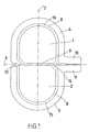
- Fig.1 shows a planar electrode, in particular a neutral electrode for radiofrequency surgery.
- the two areas bordered by solid lines are two electrode surfaces 1, 2 which are electrically separated from one another along a line-shaped insulating zone 8.
- the planar electrode shown in the form of an embodiment can be implemented in any of the known materials for the production of neutral electrodes for single or multiple use.
- the conductive surface may consist of a coated with conductive gel or adhesive metal foil.
- the linear insulating zone 8 is e.g. 2 to 5 mm wide and can be covered either completely free of conductive material, or even with weakly cross-conductive gel or adhesive. Within the scope of the invention it is also possible to use designs which deviate from these specifications as flat electrodes.
- the two electrode surfaces 1, 2 are separated from one another by the line-shaped insulating zone 8, at least partially surrounded by band-shaped extension sections 3, 4 of the respective other electrode surface.
- the two electrode surfaces 1, 2 occupy a central inner region of the electrode according to the invention.
- the band-shaped extension sections 3, 4 are narrow compared to the centrally arranged electrode surfaces 1, 2, i. their length is significantly greater than their width.
- the two electrode surfaces 1, 2 adjoin one another along one inner section 9 of the linear insulating zone 8, and the two electrode surfaces 1, 2 each have a band-shaped extension section 3, 4 which extends around the other electrode surface.
- the strip-shaped extension sections 3, 4 of the two electrode surfaces 1, 2 are guided along the outer sections 15, 16 of the line-shaped insulating zone 8 extending from the inner section 9 about the respective other electrode surface.
- a main axis 7 and a minor axis 6 of the electrode according to the invention are shown.
- the inner portion of the linear insulating zone 8 is rectilinear and extends along a minor axis 6 of the planar electrode.
- the electrode surfaces 1, 2 are formed semicircular. These ends are each surrounded by the extension sections 3, 4 by the outer sections 15, 16 of the linear insulating zone 8 sickle-shaped.
- the electrode according to the invention has an oval shape.
- the invention is not limited to these, it can also be embodied in a different geometric shape. She can be about opposite in Fig.1 illustrated construction arbitrarily compressed or stretched executed, so look from cross-divided over round to longitudinal split.
- the distance of the line-shaped insulating zone 8 can be varied from the edge within wide limits.
- the two electrode surfaces 1, 2 about an axis perpendicular to the plane of the electrode according to the invention, which extends through the intersection of the major and minor axes 7, 6 formed twice-symmetrical.
- the type of symmetry can also be designed differently.
- connecting lugs 10, 11 are arranged at one end of one of the extension sections 3, 4 of the planar electrodes 1, 2 and a transitional area between the other of the planar electrodes 1, 2 and the other extension section 3, 4.
- the terminal lugs 10, 11 extend on one side of the planar electrode in the imaginary extension of the inner portion 9 along the minor axis. 6
- Fig. 1 Shown extend the extension sections 3, 4 each in a lying along the minor axis 6 corner region 13, 14 of the surface electrodes 1, 2 away from the latter, wherein the corner regions 13, 14 with respect to the main axis 7 of the planar electrode are equally spaced.
- the band-shaped extension sections 3, 4 each extend around the other of the two electrode surfaces 1, 2 to substantially in the vicinity of the corner region 13, 14 of this other electrode surface.
- the middle region of the electrode according to the invention absorbs a comparatively small proportion of current and therefore has one lower efficiency than the edge areas.
- space and material-saving terminal lugs 24, 25 are provided in this central region, which are connected to the electrode surfaces 1, 2.
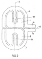
- FIG. Figure 5 . 6 and 7 show further embodiments of the invention, in which the terminal lugs 24, 25 (FIG. Figure 7 ) are arranged centrally.
- the attachment of the terminal lugs is not shown because they are also in a different way than in Fig. 7 shown done, but this does not contribute to the invention.
- the electrodes according to Fig. 5 . 6 and 7 are along the course of the band-shaped extension sections 3, 4 interrupted at one or more locations and impedances 50, 51, 52, 53 interposed to form an impedance gradient.
- the arrangement of the impedances can be done, for example, so that the minor axis 6 passes through the attachment points of the impedances 50, 51, 52, 52, whereby a stepwise increase in the impedance to the outside can be realized.
- the current distribution within the electrode according to the invention can be influenced.
- the type, sizing and locations of the impedances 50, 51, 52, 53 can be varied as needed.
- the impedances 50, 51, 52, 53 themselves as well as the electrode surfaces 1, 2 and the extension sections 3, 4 or the outer extension sections 28, 29 can be printed by printing more or less conductive lacquers.
Landscapes
- Health & Medical Sciences (AREA)
- Engineering & Computer Science (AREA)
- Life Sciences & Earth Sciences (AREA)
- Public Health (AREA)
- Animal Behavior & Ethology (AREA)
- Nuclear Medicine, Radiotherapy & Molecular Imaging (AREA)
- Surgery (AREA)
- Veterinary Medicine (AREA)
- Biomedical Technology (AREA)
- General Health & Medical Sciences (AREA)
- Radiology & Medical Imaging (AREA)
- Molecular Biology (AREA)
- Medical Informatics (AREA)
- Heart & Thoracic Surgery (AREA)
- Physics & Mathematics (AREA)
- Plasma & Fusion (AREA)
- Otolaryngology (AREA)
- Electrotherapy Devices (AREA)
- Bipolar Transistors (AREA)
- Internal Circuitry In Semiconductor Integrated Circuit Devices (AREA)
- Particle Formation And Scattering Control In Inkjet Printers (AREA)
- Inert Electrodes (AREA)
- Liquid Crystal (AREA)
- Electrodes Of Semiconductors (AREA)
- Electrolytic Production Of Metals (AREA)
- Cold Cathode And The Manufacture (AREA)
- Measurement And Recording Of Electrical Phenomena And Electrical Characteristics Of The Living Body (AREA)
- Primary Cells (AREA)
- Fixed Capacitors And Capacitor Manufacturing Machines (AREA)
Claims (12)
- Electrode plane, en particulier, électrode neutre, à des fins médicales, comportant deux surfaces d'électrodes (1, 2) électriquement séparées l'une de l'autre, de même dimension, le long d'une zone isolante (8) en forme de lignes, qui sont immédiatement adjacentes le long d'une zone de bordure partielle interne (9),
les deux surfaces d'électrodes de même taille (1, 2) présentant respectivement un segment de prolongement en forme de bande (3, 4) qui entoure respectivement l'autre surface d'électrode (1, 2) au moins le long d'une partie de bordure partielle externe (15, 16) et est ainsi séparé par la zone isolante prolongée (8) de la surface d'électrode (1, 2) environnante respective,
les deux zones de bordure partielle externes (15, 16) s'étendant essentiellement à partir d'une extrémité de la zone de bordure partielle interne (9) autour de l'autre surface d'électrode respective (1, 2) au moins vers l'autre extrémité opposée de la zone de bordure partielle interne (9), et
les deux surfaces d'électrode de même taille (1, 2) étant conçues en demi-cercle au niveau de leur extrémité opposée à la pièce interne (9) de la zone isolée (8) en forme de lignes, ladite extrémité des segments de prolongement en forme de bande (3, 4) étant entourée en forme de faucille par les pièces externes (15, 16) de la zone isolante (8) en forme de lignes, respectivement. - Electrode plane selon la revendication 1, caractérisée en ce qu'une pièce interne (9) de la zone isolante (8) en forme de lignes et les zones de bordure partielle interne adjacentes des deux surfaces d'électrodes de même taille (1, 2) évoluent de façon linéaire et s'étendent le long d'un axe secondaire (6) de l'électrode plane.
- Electrode plane selon l'une des revendications 1 ou 2, caractérisée en ce que les deux surfaces d'électrodes (1, 2) sont conçues de façon doublement symétrique autour d'un axe perpendiculairement au plan de l'électrode plane.
- Electrode plane selon l'une des revendications précédentes 1 à 3, caractérisée en ce que des axes de raccordement (10, 11) sont disposés à une extrémité de l'un des segments de prolongement (3, 4) des électrodes planes (1, 2) et dans une zone de transition entre l'autre des surfaces d'électrodes (1, 2) et de l'autre segment de prolongement (3, 4).
- Electrode plane selon la revendication 4, caractérisée en ce que les axes de raccordement (10, 11) s'étendent d'un côté de l'électrode plane dans le prolongement prévu de la pièce interne (9) le long de l'axe secondaire (6).
- Electrode plane selon l'une des revendications précédentes, caractérisée en ce que les segments de prolongement (3, 4) s'éloignent respectivement dans une zone d'angle (13, 14) située le long de l'axe secondaire (6) des électrodes planes (1, 2), les zones d'angle (13, 14) étant situées à intervalles identiques par rapport à un axe principal (7) de l'électrode plane, et en ce que les segments de prolongement (3, 4) s'étendent respectivement autour des deux surfaces d'électrodes (1, 2) jusqu'à essentiellement à proximité de la zone d'angle (13, 14) de l'autre surface d'électrode.
- Electrode plane selon l'une des revendications précédentes, caractérisée en ce qu'une proéminence (20, 21) des segments de prolongement en forme de bande (3, 4) s'étend respectivement le long de l'axe principal (7), dans l'autre surface d'électrode respective (1, 2).
- Electrode plane, en particulier selon l'une des revendications 1 à 3, caractérisée en ce que des pattes de raccordement (24, 25) sont prévues dans la zone médiane, qui sont reliées aux surfaces d'électrodes (1, 2).
- Electrode plane selon la revendication 1, caractérisée en ce que les segments de prolongement (3, 4) conduits autour de l'autre surface d'électrode respective (1, 2) sont acheminés ensuite à la zone de la surface d'électrode correspondante (1, 2) et y sont séparés par la zone isolante en forme de ligne (8) qui entoure d'autres segments de prolongement respectifs (3, 4).
- Electrode plane selon la revendication 1, caractérisée en ce que les segments de prolongement en forme de bande (3, 4) sont conduits autour des deux surfaces d'électrodes (1, 2) en évoluant en forme de spirale l'un dans l'autre, deux fois ou plus.
- Electrode plane selon l'une des revendications précédentes, caractérisée en ce que le long du parcours des segments de prolongement sous forme de bande (3, 4), celle-ci est commutée entre un ou plusieurs sites, de façon ininterrompue, et d'impédances (50, 51, 52, 53) pour former un gradient d'impédance.
- Electrode plane selon la revendication 11, caractérisée en ce que l'axe secondaire (6) passe par les sites d'apposition des impédances (50, 51, 52, 53).
Priority Applications (2)
| Application Number | Priority Date | Filing Date | Title |
|---|---|---|---|
| PL06704699T PL2007302T3 (pl) | 2005-02-23 | 2006-02-16 | Elektroda płaska |
| EP10158696.4A EP2208476B1 (fr) | 2005-02-23 | 2006-02-16 | Electrode plate |
Applications Claiming Priority (2)
| Application Number | Priority Date | Filing Date | Title |
|---|---|---|---|
| AT0030605A AT503078B1 (de) | 2005-02-23 | 2005-02-23 | Flächige elektrode |
| PCT/AT2006/000057 WO2006089319A1 (fr) | 2005-02-23 | 2006-02-16 | Electrode plane |
Related Child Applications (2)
| Application Number | Title | Priority Date | Filing Date |
|---|---|---|---|
| EP10158696.4A Division EP2208476B1 (fr) | 2005-02-23 | 2006-02-16 | Electrode plate |
| EP10158696.4 Division-Into | 2010-03-31 |
Publications (3)
| Publication Number | Publication Date |
|---|---|
| EP2007302A1 EP2007302A1 (fr) | 2008-12-31 |
| EP2007302B1 EP2007302B1 (fr) | 2010-07-14 |
| EP2007302B9 true EP2007302B9 (fr) | 2010-11-03 |
Family
ID=36208793
Family Applications (2)
| Application Number | Title | Priority Date | Filing Date |
|---|---|---|---|
| EP06704699A Expired - Lifetime EP2007302B9 (fr) | 2005-02-23 | 2006-02-16 | Electrode plane |
| EP10158696.4A Expired - Lifetime EP2208476B1 (fr) | 2005-02-23 | 2006-02-16 | Electrode plate |
Family Applications After (1)
| Application Number | Title | Priority Date | Filing Date |
|---|---|---|---|
| EP10158696.4A Expired - Lifetime EP2208476B1 (fr) | 2005-02-23 | 2006-02-16 | Electrode plate |
Country Status (8)
| Country | Link |
|---|---|
| US (1) | US8986295B2 (fr) |
| EP (2) | EP2007302B9 (fr) |
| AT (2) | AT503078B1 (fr) |
| DE (1) | DE502006007458D1 (fr) |
| DK (1) | DK2007302T3 (fr) |
| ES (1) | ES2351248T3 (fr) |
| PL (2) | PL2208476T3 (fr) |
| WO (1) | WO2006089319A1 (fr) |
Families Citing this family (6)
| Publication number | Priority date | Publication date | Assignee | Title |
|---|---|---|---|---|
| DE102012010262B4 (de) | 2012-05-25 | 2014-07-03 | Albrecht Molsberger | Therapeutisch anwendbare Gleichstromabgabevorrichtung |
| CN107907744B (zh) * | 2017-12-08 | 2020-10-23 | 赛诺微医疗科技(浙江)有限公司 | 高频电刀负极板接触质量的测量装置及方法 |
| WO2019109334A1 (fr) * | 2017-12-08 | 2019-06-13 | 赛诺微医疗科技(浙江)有限公司 | Appareil et procédé permettant de mesurer la qualité de contact d'une plaque négative de bistouri électrique à haute fréquence |
| JP7767288B2 (ja) | 2019-12-23 | 2025-11-11 | アリメトリー リミテッド | 電極パッチおよび接続システム |
| EP4186558B1 (fr) * | 2021-11-25 | 2025-01-08 | Fundación Tecnalia Research & Innovation | Électrodes de stimulation électrique et stimulation électrique d'une personne |
| CN114209418B (zh) * | 2021-12-13 | 2023-08-08 | 宝施医疗用品(深圳)有限公司 | 一种诱导式均化电流的中性电极 |
Family Cites Families (6)
| Publication number | Priority date | Publication date | Assignee | Title |
|---|---|---|---|---|
| CA1219642A (fr) * | 1984-04-18 | 1987-03-24 | Monique Frize | Electrode electrochirurgicale multi-element avec resistances d'equilibrage de la temperature |
| DE58909258D1 (de) * | 1989-09-07 | 1995-06-29 | Siemens Ag | Mehrteilige flächenhafte Elektrode für ein HF-Chirugie-gerät. |
| EP0463196A1 (fr) * | 1990-06-23 | 1992-01-02 | Erbe Elektromedizin GmbH | Electrode passive pour la chirurgie à haute fréquence |
| DE4231236C2 (de) * | 1992-09-18 | 1995-08-31 | Aesculap Ag | Flächige Elektrode für die Hochfrequenz-Chirurgie |
| AT407486B (de) * | 1999-04-29 | 2001-03-26 | Leonhard Lang Kg | Medizinische elektrode |
| US7771419B2 (en) * | 2004-10-05 | 2010-08-10 | Granite Advisory Services, Inc. | Biomedical dispersive electrode |
-
2005
- 2005-02-23 AT AT0030605A patent/AT503078B1/de not_active IP Right Cessation
-
2006
- 2006-02-16 DE DE502006007458T patent/DE502006007458D1/de not_active Expired - Lifetime
- 2006-02-16 ES ES06704699T patent/ES2351248T3/es not_active Expired - Lifetime
- 2006-02-16 EP EP06704699A patent/EP2007302B9/fr not_active Expired - Lifetime
- 2006-02-16 EP EP10158696.4A patent/EP2208476B1/fr not_active Expired - Lifetime
- 2006-02-16 DK DK06704699.5T patent/DK2007302T3/da active
- 2006-02-16 AT AT06704699T patent/ATE473703T1/de active
- 2006-02-16 PL PL10158696T patent/PL2208476T3/pl unknown
- 2006-02-16 WO PCT/AT2006/000057 patent/WO2006089319A1/fr not_active Ceased
- 2006-02-16 US US12/515,042 patent/US8986295B2/en active Active
- 2006-02-16 PL PL06704699T patent/PL2007302T3/pl unknown
Also Published As
| Publication number | Publication date |
|---|---|
| EP2007302A1 (fr) | 2008-12-31 |
| PL2208476T3 (pl) | 2017-07-31 |
| EP2007302B1 (fr) | 2010-07-14 |
| HK1126642A1 (en) | 2009-09-11 |
| EP2208476A9 (fr) | 2010-10-27 |
| EP2208476A1 (fr) | 2010-07-21 |
| US20100036377A1 (en) | 2010-02-11 |
| PL2007302T3 (pl) | 2011-03-31 |
| AT503078A1 (de) | 2007-07-15 |
| US8986295B2 (en) | 2015-03-24 |
| EP2208476B1 (fr) | 2016-07-20 |
| AT503078B1 (de) | 2010-10-15 |
| ES2351248T3 (es) | 2011-02-02 |
| DE502006007458D1 (de) | 2010-08-26 |
| ATE473703T1 (de) | 2010-07-15 |
| WO2006089319A1 (fr) | 2006-08-31 |
| DK2007302T3 (da) | 2010-11-15 |
Similar Documents
| Publication | Publication Date | Title |
|---|---|---|
| DE3916161C2 (fr) | ||
| DE69033498T2 (de) | Elektrischer Verbinder | |
| EP2842506B1 (fr) | Instrument médical et système électrochirurgical | |
| DE3623293C2 (de) | Mehrteilige Flachelektrode, insbesondere für die HF-Chirurgie | |
| EP0416159A1 (fr) | Plaque-électrode collante pour un appareil de chirurgie haute fréquence | |
| DE3206947A1 (de) | Neutrale elektrode fuer die hochfrequenz-chirurgie | |
| DE112012002861T5 (de) | Shunt-Widerstand und Verfahren zur Herstellung desselben | |
| DE102013001156A1 (de) | Bipolares Resektoskop | |
| EP3477784B1 (fr) | Dispositif de traitement pour un instrument médical microinvasif | |
| EP2427130A1 (fr) | Instrument médical | |
| DE102006006052A1 (de) | Hochfrequenz-Behandlungsgerät für ein Endoskop | |
| EP1163885B1 (fr) | Instrument endoscopique avec deux électrodes | |
| EP2007302B1 (fr) | Electrode plane | |
| DE102007042524A1 (de) | Koagulationsschablone und Applikationsvorrichtung | |
| DE102012007652A1 (de) | Werkzeug für ein medizinisches Instrument | |
| DE19526243C1 (de) | Elektrode zum Vaporisieren von Gewebe | |
| DE1039148B (de) | Elektrode zur Erzeugung eines hochfrequenten magnetischen Wirbelfeldes | |
| EP3416577B1 (fr) | Prise multiple pour appareil chirurgical, générateur haute fréquence électrochirurgical et système électrochirurgical | |
| DE102018204036B4 (de) | Implantat in Art einer Wickelmanschetten-Elektrodenanordnung | |
| DE3518245A1 (de) | Elektrisches koaxialkabel mit integriertem heizelement | |
| EP3791782B1 (fr) | Cathéter pourvu de carte de circuit imprimé flexible et procédé de fabrication de carte de circuit imprimé flexible | |
| DE202023106679U1 (de) | Leiter eines Physiotherapiegeräts und Physiotherapiegerät | |
| EP3957231A1 (fr) | Carte de circuit imprimé flexible et cathéter doté d'une telle carte de circuit imprimé | |
| DE2025384C3 (de) | Spannungssteuerung im stirnseitigen Endbereich von Lagenwicklungen von Transformatoren | |
| DE202006002796U1 (de) | Endoskopische Zange mit drei Gelenken |
Legal Events
| Date | Code | Title | Description |
|---|---|---|---|
| PUAI | Public reference made under article 153(3) epc to a published international application that has entered the european phase |
Free format text: ORIGINAL CODE: 0009012 |
|
| 17P | Request for examination filed |
Effective date: 20070820 |
|
| AK | Designated contracting states |
Kind code of ref document: A1 Designated state(s): AT BE BG CH CY CZ DE DK EE ES FI FR GB GR HU IE IS IT LI LT LU LV MC NL PL PT RO SE SI SK TR |
|
| AX | Request for extension of the european patent |
Extension state: AL BA HR MK YU |
|
| 17Q | First examination report despatched |
Effective date: 20081223 |
|
| REG | Reference to a national code |
Ref country code: HK Ref legal event code: DE Ref document number: 1126642 Country of ref document: HK |
|
| GRAP | Despatch of communication of intention to grant a patent |
Free format text: ORIGINAL CODE: EPIDOSNIGR1 |
|
| GRAS | Grant fee paid |
Free format text: ORIGINAL CODE: EPIDOSNIGR3 |
|
| GRAA | (expected) grant |
Free format text: ORIGINAL CODE: 0009210 |
|
| AK | Designated contracting states |
Kind code of ref document: B1 Designated state(s): AT BE BG CH CY CZ DE DK EE ES FI FR GB GR HU IE IS IT LI LT LU LV MC NL PL PT RO SE SI SK TR |
|
| AX | Request for extension of the european patent |
Extension state: AL BA HR MK YU |
|
| REG | Reference to a national code |
Ref country code: GB Ref legal event code: FG4D Free format text: NOT ENGLISH |
|
| REG | Reference to a national code |
Ref country code: CH Ref legal event code: EP |
|
| REG | Reference to a national code |
Ref country code: IE Ref legal event code: FG4D |
|
| REF | Corresponds to: |
Ref document number: 502006007458 Country of ref document: DE Date of ref document: 20100826 Kind code of ref document: P |
|
| REG | Reference to a national code |
Ref country code: NL Ref legal event code: VDEP Effective date: 20100714 |
|
| REG | Reference to a national code |
Ref country code: DK Ref legal event code: T3 |
|
| REG | Reference to a national code |
Ref country code: GR Ref legal event code: EP Ref document number: 20100402390 Country of ref document: GR |
|
| LTIE | Lt: invalidation of european patent or patent extension |
Effective date: 20100714 |
|
| PG25 | Lapsed in a contracting state [announced via postgrant information from national office to epo] |
Ref country code: NL Free format text: LAPSE BECAUSE OF FAILURE TO SUBMIT A TRANSLATION OF THE DESCRIPTION OR TO PAY THE FEE WITHIN THE PRESCRIBED TIME-LIMIT Effective date: 20100714 Ref country code: FI Free format text: LAPSE BECAUSE OF FAILURE TO SUBMIT A TRANSLATION OF THE DESCRIPTION OR TO PAY THE FEE WITHIN THE PRESCRIBED TIME-LIMIT Effective date: 20100714 Ref country code: LT Free format text: LAPSE BECAUSE OF FAILURE TO SUBMIT A TRANSLATION OF THE DESCRIPTION OR TO PAY THE FEE WITHIN THE PRESCRIBED TIME-LIMIT Effective date: 20100714 |
|
| REG | Reference to a national code |
Ref country code: ES Ref legal event code: FG2A Effective date: 20110121 |
|
| REG | Reference to a national code |
Ref country code: IE Ref legal event code: FD4D |
|
| PG25 | Lapsed in a contracting state [announced via postgrant information from national office to epo] |
Ref country code: SI Free format text: LAPSE BECAUSE OF FAILURE TO SUBMIT A TRANSLATION OF THE DESCRIPTION OR TO PAY THE FEE WITHIN THE PRESCRIBED TIME-LIMIT Effective date: 20100714 Ref country code: PT Free format text: LAPSE BECAUSE OF FAILURE TO SUBMIT A TRANSLATION OF THE DESCRIPTION OR TO PAY THE FEE WITHIN THE PRESCRIBED TIME-LIMIT Effective date: 20101115 Ref country code: IS Free format text: LAPSE BECAUSE OF FAILURE TO SUBMIT A TRANSLATION OF THE DESCRIPTION OR TO PAY THE FEE WITHIN THE PRESCRIBED TIME-LIMIT Effective date: 20101114 Ref country code: CY Free format text: LAPSE BECAUSE OF FAILURE TO SUBMIT A TRANSLATION OF THE DESCRIPTION OR TO PAY THE FEE WITHIN THE PRESCRIBED TIME-LIMIT Effective date: 20100714 Ref country code: BG Free format text: LAPSE BECAUSE OF FAILURE TO SUBMIT A TRANSLATION OF THE DESCRIPTION OR TO PAY THE FEE WITHIN THE PRESCRIBED TIME-LIMIT Effective date: 20101014 |
|
| REG | Reference to a national code |
Ref country code: HK Ref legal event code: GR Ref document number: 1126642 Country of ref document: HK |
|
| PG25 | Lapsed in a contracting state [announced via postgrant information from national office to epo] |
Ref country code: LV Free format text: LAPSE BECAUSE OF FAILURE TO SUBMIT A TRANSLATION OF THE DESCRIPTION OR TO PAY THE FEE WITHIN THE PRESCRIBED TIME-LIMIT Effective date: 20100714 Ref country code: SE Free format text: LAPSE BECAUSE OF FAILURE TO SUBMIT A TRANSLATION OF THE DESCRIPTION OR TO PAY THE FEE WITHIN THE PRESCRIBED TIME-LIMIT Effective date: 20100714 |
|
| REG | Reference to a national code |
Ref country code: PL Ref legal event code: T3 |
|
| PG25 | Lapsed in a contracting state [announced via postgrant information from national office to epo] |
Ref country code: IE Free format text: LAPSE BECAUSE OF FAILURE TO SUBMIT A TRANSLATION OF THE DESCRIPTION OR TO PAY THE FEE WITHIN THE PRESCRIBED TIME-LIMIT Effective date: 20100714 |
|
| PLBE | No opposition filed within time limit |
Free format text: ORIGINAL CODE: 0009261 |
|
| STAA | Information on the status of an ep patent application or granted ep patent |
Free format text: STATUS: NO OPPOSITION FILED WITHIN TIME LIMIT |
|
| PG25 | Lapsed in a contracting state [announced via postgrant information from national office to epo] |
Ref country code: CZ Free format text: LAPSE BECAUSE OF FAILURE TO SUBMIT A TRANSLATION OF THE DESCRIPTION OR TO PAY THE FEE WITHIN THE PRESCRIBED TIME-LIMIT Effective date: 20100714 Ref country code: EE Free format text: LAPSE BECAUSE OF FAILURE TO SUBMIT A TRANSLATION OF THE DESCRIPTION OR TO PAY THE FEE WITHIN THE PRESCRIBED TIME-LIMIT Effective date: 20100714 Ref country code: SK Free format text: LAPSE BECAUSE OF FAILURE TO SUBMIT A TRANSLATION OF THE DESCRIPTION OR TO PAY THE FEE WITHIN THE PRESCRIBED TIME-LIMIT Effective date: 20100714 Ref country code: RO Free format text: LAPSE BECAUSE OF FAILURE TO SUBMIT A TRANSLATION OF THE DESCRIPTION OR TO PAY THE FEE WITHIN THE PRESCRIBED TIME-LIMIT Effective date: 20100714 |
|
| 26N | No opposition filed |
Effective date: 20110415 |
|
| REG | Reference to a national code |
Ref country code: DE Ref legal event code: R097 Ref document number: 502006007458 Country of ref document: DE Effective date: 20110415 |
|
| BERE | Be: lapsed |
Owner name: NESSLER MEDIZINTECHNIK GMBH Effective date: 20110228 |
|
| PG25 | Lapsed in a contracting state [announced via postgrant information from national office to epo] |
Ref country code: MC Free format text: LAPSE BECAUSE OF NON-PAYMENT OF DUE FEES Effective date: 20110228 |
|
| REG | Reference to a national code |
Ref country code: CH Ref legal event code: PL |
|
| PG25 | Lapsed in a contracting state [announced via postgrant information from national office to epo] |
Ref country code: CH Free format text: LAPSE BECAUSE OF NON-PAYMENT OF DUE FEES Effective date: 20110228 Ref country code: LI Free format text: LAPSE BECAUSE OF NON-PAYMENT OF DUE FEES Effective date: 20110228 |
|
| PG25 | Lapsed in a contracting state [announced via postgrant information from national office to epo] |
Ref country code: BE Free format text: LAPSE BECAUSE OF NON-PAYMENT OF DUE FEES Effective date: 20110228 |
|
| REG | Reference to a national code |
Ref country code: CH Ref legal event code: NV Representative=s name: RIEDERER HASLER & PARTNER PATENTANWAELTE AG Ref country code: CH Ref legal event code: AEN Free format text: DAS PATENT IST AUFGRUND DES WEITERBEHANDLUNGSANTRAGS VOM 25.10.2011 REAKTIVIERT WORDEN. |
|
| PGRI | Patent reinstated in contracting state [announced from national office to epo] |
Ref country code: CH Effective date: 20111122 |
|
| PG25 | Lapsed in a contracting state [announced via postgrant information from national office to epo] |
Ref country code: LU Free format text: LAPSE BECAUSE OF NON-PAYMENT OF DUE FEES Effective date: 20110216 |
|
| PG25 | Lapsed in a contracting state [announced via postgrant information from national office to epo] |
Ref country code: HU Free format text: LAPSE BECAUSE OF FAILURE TO SUBMIT A TRANSLATION OF THE DESCRIPTION OR TO PAY THE FEE WITHIN THE PRESCRIBED TIME-LIMIT Effective date: 20100714 |
|
| REG | Reference to a national code |
Ref country code: FR Ref legal event code: PLFP Year of fee payment: 11 |
|
| PGFP | Annual fee paid to national office [announced via postgrant information from national office to epo] |
Ref country code: ES Payment date: 20160223 Year of fee payment: 11 Ref country code: DK Payment date: 20160222 Year of fee payment: 11 Ref country code: IT Payment date: 20160223 Year of fee payment: 11 Ref country code: CH Payment date: 20160301 Year of fee payment: 11 Ref country code: TR Payment date: 20160211 Year of fee payment: 11 |
|
| PGFP | Annual fee paid to national office [announced via postgrant information from national office to epo] |
Ref country code: GR Payment date: 20160323 Year of fee payment: 11 |
|
| REG | Reference to a national code |
Ref country code: FR Ref legal event code: PLFP Year of fee payment: 12 |
|
| PGFP | Annual fee paid to national office [announced via postgrant information from national office to epo] |
Ref country code: AT Payment date: 20170228 Year of fee payment: 12 |
|
| REG | Reference to a national code |
Ref country code: DK Ref legal event code: EBP Effective date: 20170228 |
|
| REG | Reference to a national code |
Ref country code: CH Ref legal event code: PL |
|
| PG25 | Lapsed in a contracting state [announced via postgrant information from national office to epo] |
Ref country code: CH Free format text: LAPSE BECAUSE OF NON-PAYMENT OF DUE FEES Effective date: 20170228 Ref country code: GR Free format text: LAPSE BECAUSE OF NON-PAYMENT OF DUE FEES Effective date: 20170906 Ref country code: LI Free format text: LAPSE BECAUSE OF NON-PAYMENT OF DUE FEES Effective date: 20170228 |
|
| PG25 | Lapsed in a contracting state [announced via postgrant information from national office to epo] |
Ref country code: DK Free format text: LAPSE BECAUSE OF NON-PAYMENT OF DUE FEES Effective date: 20170228 |
|
| REG | Reference to a national code |
Ref country code: FR Ref legal event code: PLFP Year of fee payment: 13 |
|
| PG25 | Lapsed in a contracting state [announced via postgrant information from national office to epo] |
Ref country code: IT Free format text: LAPSE BECAUSE OF NON-PAYMENT OF DUE FEES Effective date: 20170216 |
|
| REG | Reference to a national code |
Ref country code: ES Ref legal event code: FD2A Effective date: 20180704 |
|
| PG25 | Lapsed in a contracting state [announced via postgrant information from national office to epo] |
Ref country code: ES Free format text: LAPSE BECAUSE OF NON-PAYMENT OF DUE FEES Effective date: 20170217 |
|
| REG | Reference to a national code |
Ref country code: AT Ref legal event code: MM01 Ref document number: 473703 Country of ref document: AT Kind code of ref document: T Effective date: 20180216 |
|
| PG25 | Lapsed in a contracting state [announced via postgrant information from national office to epo] |
Ref country code: AT Free format text: LAPSE BECAUSE OF NON-PAYMENT OF DUE FEES Effective date: 20180216 |
|
| PG25 | Lapsed in a contracting state [announced via postgrant information from national office to epo] |
Ref country code: TR Free format text: LAPSE BECAUSE OF NON-PAYMENT OF DUE FEES Effective date: 20170216 |
|
| PGFP | Annual fee paid to national office [announced via postgrant information from national office to epo] |
Ref country code: DE Payment date: 20250225 Year of fee payment: 20 |
|
| PGFP | Annual fee paid to national office [announced via postgrant information from national office to epo] |
Ref country code: PL Payment date: 20250217 Year of fee payment: 20 Ref country code: FR Payment date: 20250227 Year of fee payment: 20 |
|
| PGFP | Annual fee paid to national office [announced via postgrant information from national office to epo] |
Ref country code: GB Payment date: 20250225 Year of fee payment: 20 |
|
| REG | Reference to a national code |
Ref country code: DE Ref legal event code: R071 Ref document number: 502006007458 Country of ref document: DE |
|
| REG | Reference to a national code |
Ref country code: GB Ref legal event code: PE20 Expiry date: 20260215 |