EP2008748A2 - Mandrin à pince de serrage - Google Patents
Mandrin à pince de serrage Download PDFInfo
- Publication number
- EP2008748A2 EP2008748A2 EP08011325A EP08011325A EP2008748A2 EP 2008748 A2 EP2008748 A2 EP 2008748A2 EP 08011325 A EP08011325 A EP 08011325A EP 08011325 A EP08011325 A EP 08011325A EP 2008748 A2 EP2008748 A2 EP 2008748A2
- Authority
- EP
- European Patent Office
- Prior art keywords
- collet chuck
- collet
- pressure
- pressure sleeve
- sleeve
- Prior art date
- Legal status (The legal status is an assumption and is not a legal conclusion. Google has not performed a legal analysis and makes no representation as to the accuracy of the status listed.)
- Withdrawn
Links
Images
Classifications
-
- B—PERFORMING OPERATIONS; TRANSPORTING
- B23—MACHINE TOOLS; METAL-WORKING NOT OTHERWISE PROVIDED FOR
- B23B—TURNING; BORING
- B23B31/00—Chucks; Expansion mandrels; Adaptations thereof for remote control
- B23B31/02—Chucks
- B23B31/10—Chucks characterised by the retaining or gripping devices or their immediate operating means
- B23B31/12—Chucks with simultaneously-acting jaws, whether or not also individually adjustable
- B23B31/20—Longitudinally-split sleeves, e.g. collet chucks
- B23B31/201—Characterized by features relating primarily to remote control of the gripping means
- B23B31/204—Characterized by features relating primarily to remote control of the gripping means using fluid-pressure means to actuate the gripping means
-
- B—PERFORMING OPERATIONS; TRANSPORTING
- B23—MACHINE TOOLS; METAL-WORKING NOT OTHERWISE PROVIDED FOR
- B23B—TURNING; BORING
- B23B31/00—Chucks; Expansion mandrels; Adaptations thereof for remote control
- B23B31/02—Chucks
- B23B31/10—Chucks characterised by the retaining or gripping devices or their immediate operating means
- B23B31/12—Chucks with simultaneously-acting jaws, whether or not also individually adjustable
- B23B31/20—Longitudinally-split sleeves, e.g. collet chucks
- B23B31/208—Longitudinally-split sleeves, e.g. collet chucks with a tool positioning stop
Definitions
- the invention relates to a collet chuck, which has for receiving a collet into which a tool is inserted, a conical opening which is provided in a pressure sleeve which is axially displaceable in the collet chuck, and wherein the collet in the conical opening by a clamping nut and is tensioned by further means, wherein the pressure sleeve is displaceable by the further means in the axial direction.
- Such a collet chuck is from the DE 39 38 689 A1 known.
- the other means are formed by two mutually radially opposite clamping parts, which are pulled by a screw against each other and thereby oblique effective surfaces on also inclined active surfaces of the Press sleeve and this press it in one direction, causing a further tensioning of the collet in the conical opening of the collet chuck causes.
- This arrangement is mechanically very complex, since it consists of relatively many parts, all of which must be worked very precisely.
- a similar arrangement is from the DE 197 29 249 C2 known.
- the invention is based on the object to further improve the clamping of a collet chuck in a collet chuck of the type mentioned and simplify. It should also be a higher pressure with which the collet is tensioned, be possible.
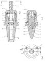
- the collet chuck 1 does not include the collet 2 directly. Rather, in the collet chuck 1, a pressure sleeve 3, which is displaceable in a bore 1 'in the axial direction, is provided, which has a conical opening 4 has, in which the collet 2 with tool 7, for example, a cutter, is used.
- the collet 2 is received in the pressure sleeve 3 and this in the collet chuck 1 characterized in that the clamping nut 5 is screwed onto the external thread 6 on the collet chuck 1.
- a first tightening takes place initially by tightening the clamping nut 5. Further tightening takes place in that the pressure sleeve 3 is displaced in the axial direction. This is done hydraulically characterized in that the piston 8 by tightening a threaded pin 9, which can be screwed with a Allen screwdriver into a thread in the collet chuck 1, characterized shifted so that in the pressure chamber 10 pressure on a incompressible hydraulic medium, for example oil, is exercised.
- a threaded pin 9 which can be screwed with a Allen screwdriver into a thread in the collet chuck 1, characterized shifted so that in the pressure chamber 10 pressure on a incompressible hydraulic medium, for example oil, is exercised.
- the pressure chamber 10 communicates via a line 11 with the sealed by sealing rings 20 and 21 (each formed by an O-ring with support disk) space, on the one hand between the bottom 12 of the pressure sleeve 3 and the bottom 13 of the associated recess 14 in the collet chuck 1 and on the other hand, between the cylindrical outer surface of the pressure sleeve 3 and the cylindrical inner surface of the recess 14 is formed, so that an increase in pressure by screwing the threaded pin 9, a displacement of the pressure sleeve 3 in the axial direction, ie to the right in FIG. 3 , causes.
- the pressurized hydraulic medium in the said space between the seals 20 and 21, in particular in the gap between the outer surface of the pressure sleeve 3 and the cylindrical inner surface of the recess 14 forms a film. This causes a damping of the vibrations of the tool 7, which in the Machining a workpiece arise and would otherwise be transferred to the collet chuck.
- the mentioned gap is not shown in the drawing. He is in reality only a few hundredths of a millimeter wide.
- a vent line 19 is provided for venting the pressure chamber 10. It is also a force acting on a ball 15 threaded pin 16 is provided, which can be solved by a Allen screwdriver, so that a vent takes place to the outside.
- a stop screw 17 is designated, which forms a stop for the tool used 7. It is inserted into an internal thread in the bore 18 in the collet chuck 1.
Landscapes
- Engineering & Computer Science (AREA)
- Mechanical Engineering (AREA)
- Gripping On Spindles (AREA)
Applications Claiming Priority (1)
| Application Number | Priority Date | Filing Date | Title |
|---|---|---|---|
| DE200710030859 DE102007030859A1 (de) | 2007-06-25 | 2007-06-25 | Spannzangenfutter |
Publications (2)
| Publication Number | Publication Date |
|---|---|
| EP2008748A2 true EP2008748A2 (fr) | 2008-12-31 |
| EP2008748A3 EP2008748A3 (fr) | 2009-04-08 |
Family
ID=39816819
Family Applications (1)
| Application Number | Title | Priority Date | Filing Date |
|---|---|---|---|
| EP08011325A Withdrawn EP2008748A3 (fr) | 2007-06-25 | 2008-06-23 | Mandrin à pince de serrage |
Country Status (2)
| Country | Link |
|---|---|
| EP (1) | EP2008748A3 (fr) |
| DE (1) | DE102007030859A1 (fr) |
Cited By (4)
| Publication number | Priority date | Publication date | Assignee | Title |
|---|---|---|---|---|
| DE102009044049A1 (de) | 2009-09-18 | 2011-03-24 | Röhm Gmbh | Spannzangenfutter |
| CN103659391A (zh) * | 2013-12-06 | 2014-03-26 | 常熟量具刃具厂 | 锥柄自动夹持装置 |
| JP2014159054A (ja) * | 2013-02-19 | 2014-09-04 | Seibu Electric & Mach Co Ltd | ワークの固定方法及びワーク保持装置 |
| US11732804B2 (en) | 2019-10-11 | 2023-08-22 | Kennametal Inc. | Hydraulic tool mount and sealing piston for such a mount |
Citations (2)
| Publication number | Priority date | Publication date | Assignee | Title |
|---|---|---|---|---|
| DE3938689A1 (de) | 1989-11-22 | 1991-05-23 | Erich Wezel | Spannzangenhalter |
| DE19729249C2 (de) | 1996-07-23 | 2002-02-28 | Fahrion Eugen Gmbh | Spannfutter |
Family Cites Families (4)
| Publication number | Priority date | Publication date | Assignee | Title |
|---|---|---|---|---|
| DE1141157B (de) * | 1954-02-03 | 1962-12-13 | Crawford Collets Ltd | Hydraulisch betaetigtes Spannfutter |
| DE3408266A1 (de) * | 1983-03-30 | 1984-10-04 | Albert Schrem Werkzeugfabrik GmbH, 7928 Giengen | Hydraulische spannmutter zum gegenseitigen axialen zusammenspannen zweier werkstueck- oder maschinenteile |
| DE10330131A1 (de) * | 2003-07-04 | 2005-01-20 | Zeitlauf Gmbh Antriebstechnik & Co Kg | Spannvorrichtung, insbesondere für Wechselwerkzeuge |
| DE202004010714U1 (de) | 2004-07-08 | 2004-09-16 | Eugen Fahrion Gmbh & Co. | Spannzangenfutter |
-
2007
- 2007-06-25 DE DE200710030859 patent/DE102007030859A1/de not_active Withdrawn
-
2008
- 2008-06-23 EP EP08011325A patent/EP2008748A3/fr not_active Withdrawn
Patent Citations (2)
| Publication number | Priority date | Publication date | Assignee | Title |
|---|---|---|---|---|
| DE3938689A1 (de) | 1989-11-22 | 1991-05-23 | Erich Wezel | Spannzangenhalter |
| DE19729249C2 (de) | 1996-07-23 | 2002-02-28 | Fahrion Eugen Gmbh | Spannfutter |
Cited By (6)
| Publication number | Priority date | Publication date | Assignee | Title |
|---|---|---|---|---|
| DE102009044049A1 (de) | 2009-09-18 | 2011-03-24 | Röhm Gmbh | Spannzangenfutter |
| WO2011032552A1 (fr) | 2009-09-18 | 2011-03-24 | Röhm Gmbh | Mandrin à pinces |
| CN102655969A (zh) * | 2009-09-18 | 2012-09-05 | 罗姆股份有限公司 | 夹头卡盘 |
| JP2014159054A (ja) * | 2013-02-19 | 2014-09-04 | Seibu Electric & Mach Co Ltd | ワークの固定方法及びワーク保持装置 |
| CN103659391A (zh) * | 2013-12-06 | 2014-03-26 | 常熟量具刃具厂 | 锥柄自动夹持装置 |
| US11732804B2 (en) | 2019-10-11 | 2023-08-22 | Kennametal Inc. | Hydraulic tool mount and sealing piston for such a mount |
Also Published As
| Publication number | Publication date |
|---|---|
| DE102007030859A1 (de) | 2009-01-02 |
| EP2008748A3 (fr) | 2009-04-08 |
Similar Documents
| Publication | Publication Date | Title |
|---|---|---|
| EP1999391B1 (fr) | Dispositif d'actionnement d'un accouplement a lamelles dans une transmission | |
| EP1529585B1 (fr) | Dispositif de serrage expansible | |
| EP2299141B1 (fr) | Dispositif de freinage et/ou de serrage doté d'un corps central à forme rigide | |
| EP1584389B1 (fr) | Dispositif de serrage expansible | |
| DE102007012487A1 (de) | Werkzeughalter | |
| EP2832478B1 (fr) | Système de connexion et douille intermédiaire et kit doté d'une douille intermédiaire et d'une vis d'arrêt destinée à être utilisée dans un tel système de connexion | |
| DE102016002947B4 (de) | Dehnspanneinrichtung | |
| EP3403749B1 (fr) | Butée pour une broche d'usinage d'une machine d'usinage et procédé de serrage de butée | |
| EP2008748A2 (fr) | Mandrin à pince de serrage | |
| EP2090794B1 (fr) | Agencement de palier | |
| EP3403758A1 (fr) | Adaptateur réglable | |
| EP2345495A2 (fr) | Dispositif de serrage d'une pièce ou d'un outil sur une broche de travail | |
| EP3815822A1 (fr) | Mandrin hydraulique | |
| DE102016008767A1 (de) | Dehnspanneinrichtung | |
| DE102009050701A1 (de) | Spanneinrichtung | |
| EP4155023A1 (fr) | Logement pour un outil rotatif | |
| DE1966073B2 (de) | Druckmittelübertrager an einer Werkzeugmaschine o.dgl | |
| DE10125154B4 (de) | Vorrichtung zum lösbaren Halten eines Werkzeuges sowie Spannhülse hierfür | |
| DE102018214189A1 (de) | Dehnspannfutter | |
| DE102004023231B4 (de) | Einrichtung mit einer Drehdurchführung für eine Flüssigkeit | |
| EP4385659B1 (fr) | Dispositif de serrage | |
| DE202006009555U1 (de) | Klemmvorrichtung zur Aufnahme von Werkstücken in einer Werkzeugmaschine | |
| DE10361622B3 (de) | Schneidwerkzeug | |
| DE102007054378A1 (de) | Lageranordnung | |
| DE102021124802A1 (de) | Schleifscheibenaufnahme |
Legal Events
| Date | Code | Title | Description |
|---|---|---|---|
| PUAI | Public reference made under article 153(3) epc to a published international application that has entered the european phase |
Free format text: ORIGINAL CODE: 0009012 |
|
| AK | Designated contracting states |
Kind code of ref document: A2 Designated state(s): AT BE BG CH CY CZ DE DK EE ES FI FR GB GR HR HU IE IS IT LI LT LU LV MC MT NL NO PL PT RO SE SI SK TR |
|
| AX | Request for extension of the european patent |
Extension state: AL BA MK RS |
|
| PUAL | Search report despatched |
Free format text: ORIGINAL CODE: 0009013 |
|
| AK | Designated contracting states |
Kind code of ref document: A3 Designated state(s): AT BE BG CH CY CZ DE DK EE ES FI FR GB GR HR HU IE IS IT LI LT LU LV MC MT NL NO PL PT RO SE SI SK TR |
|
| AX | Request for extension of the european patent |
Extension state: AL BA MK RS |
|
| AKX | Designation fees paid | ||
| STAA | Information on the status of an ep patent application or granted ep patent |
Free format text: STATUS: THE APPLICATION IS DEEMED TO BE WITHDRAWN |
|
| 18D | Application deemed to be withdrawn |
Effective date: 20091009 |
|
| REG | Reference to a national code |
Ref country code: DE Ref legal event code: 8566 |