EP2090794B1 - Agencement de palier - Google Patents
Agencement de palier Download PDFInfo
- Publication number
- EP2090794B1 EP2090794B1 EP08172090A EP08172090A EP2090794B1 EP 2090794 B1 EP2090794 B1 EP 2090794B1 EP 08172090 A EP08172090 A EP 08172090A EP 08172090 A EP08172090 A EP 08172090A EP 2090794 B1 EP2090794 B1 EP 2090794B1
- Authority
- EP
- European Patent Office
- Prior art keywords
- pressure
- bearing
- chamber
- piston
- pressure chamber
- Prior art date
- Legal status (The legal status is an assumption and is not a legal conclusion. Google has not performed a legal analysis and makes no representation as to the accuracy of the status listed.)
- Not-in-force
Links
- 238000007789 sealing Methods 0.000 claims description 22
- 239000012530 fluid Substances 0.000 claims description 19
- 239000000463 material Substances 0.000 claims description 2
- 239000012528 membrane Substances 0.000 description 35
- 238000005096 rolling process Methods 0.000 description 26
- 238000013461 design Methods 0.000 description 10
- 230000008878 coupling Effects 0.000 description 9
- 238000010168 coupling process Methods 0.000 description 9
- 238000005859 coupling reaction Methods 0.000 description 9
- 238000007667 floating Methods 0.000 description 8
- 230000008901 benefit Effects 0.000 description 5
- 238000010438 heat treatment Methods 0.000 description 4
- 230000010354 integration Effects 0.000 description 4
- 239000002184 metal Substances 0.000 description 4
- 239000003921 oil Substances 0.000 description 4
- 230000002829 reductive effect Effects 0.000 description 4
- 230000002441 reversible effect Effects 0.000 description 4
- 230000006835 compression Effects 0.000 description 3
- 238000007906 compression Methods 0.000 description 3
- 238000011161 development Methods 0.000 description 3
- 238000011038 discontinuous diafiltration by volume reduction Methods 0.000 description 3
- 239000010720 hydraulic oil Substances 0.000 description 3
- 230000036961 partial effect Effects 0.000 description 3
- 239000000565 sealant Substances 0.000 description 3
- 239000007787 solid Substances 0.000 description 3
- 230000003068 static effect Effects 0.000 description 3
- 238000011144 upstream manufacturing Methods 0.000 description 3
- 238000013459 approach Methods 0.000 description 2
- 238000005452 bending Methods 0.000 description 2
- 230000005540 biological transmission Effects 0.000 description 2
- 230000008859 change Effects 0.000 description 2
- 238000010276 construction Methods 0.000 description 2
- 238000001816 cooling Methods 0.000 description 2
- 238000006073 displacement reaction Methods 0.000 description 2
- 238000005476 soldering Methods 0.000 description 2
- 230000008646 thermal stress Effects 0.000 description 2
- 239000003190 viscoelastic substance Substances 0.000 description 2
- 238000003466 welding Methods 0.000 description 2
- 230000001133 acceleration Effects 0.000 description 1
- 239000000853 adhesive Substances 0.000 description 1
- 230000001070 adhesive effect Effects 0.000 description 1
- 230000002411 adverse Effects 0.000 description 1
- 230000006378 damage Effects 0.000 description 1
- 230000001419 dependent effect Effects 0.000 description 1
- 238000010586 diagram Methods 0.000 description 1
- 238000007599 discharging Methods 0.000 description 1
- 230000020169 heat generation Effects 0.000 description 1
- 235000015095 lager Nutrition 0.000 description 1
- 238000000034 method Methods 0.000 description 1
- 238000012545 processing Methods 0.000 description 1
- 238000009420 retrofitting Methods 0.000 description 1
- 230000035882 stress Effects 0.000 description 1
- 230000008093 supporting effect Effects 0.000 description 1
Images


Classifications
-
- F—MECHANICAL ENGINEERING; LIGHTING; HEATING; WEAPONS; BLASTING
- F16—ENGINEERING ELEMENTS AND UNITS; GENERAL MEASURES FOR PRODUCING AND MAINTAINING EFFECTIVE FUNCTIONING OF MACHINES OR INSTALLATIONS; THERMAL INSULATION IN GENERAL
- F16C—SHAFTS; FLEXIBLE SHAFTS; ELEMENTS OR CRANKSHAFT MECHANISMS; ROTARY BODIES OTHER THAN GEARING ELEMENTS; BEARINGS
- F16C25/00—Bearings for exclusively rotary movement adjustable for wear or play
- F16C25/06—Ball or roller bearings
-
- B—PERFORMING OPERATIONS; TRANSPORTING
- B23—MACHINE TOOLS; METAL-WORKING NOT OTHERWISE PROVIDED FOR
- B23Q—DETAILS, COMPONENTS, OR ACCESSORIES FOR MACHINE TOOLS, e.g. ARRANGEMENTS FOR COPYING OR CONTROLLING; MACHINE TOOLS IN GENERAL CHARACTERISED BY THE CONSTRUCTION OF PARTICULAR DETAILS OR COMPONENTS; COMBINATIONS OR ASSOCIATIONS OF METAL-WORKING MACHINES, NOT DIRECTED TO A PARTICULAR RESULT
- B23Q1/00—Members which are comprised in the general build-up of a form of machine, particularly relatively large fixed members
- B23Q1/25—Movable or adjustable work or tool supports
- B23Q1/26—Movable or adjustable work or tool supports characterised by constructional features relating to the co-operation of relatively movable members; Means for preventing relative movement of such members
- B23Q1/34—Relative movement obtained by use of deformable elements, e.g. piezoelectric, magnetostrictive, elastic or thermally-dilatable elements
-
- F—MECHANICAL ENGINEERING; LIGHTING; HEATING; WEAPONS; BLASTING
- F16—ENGINEERING ELEMENTS AND UNITS; GENERAL MEASURES FOR PRODUCING AND MAINTAINING EFFECTIVE FUNCTIONING OF MACHINES OR INSTALLATIONS; THERMAL INSULATION IN GENERAL
- F16C—SHAFTS; FLEXIBLE SHAFTS; ELEMENTS OR CRANKSHAFT MECHANISMS; ROTARY BODIES OTHER THAN GEARING ELEMENTS; BEARINGS
- F16C19/00—Bearings with rolling contact, for exclusively rotary movement
- F16C19/52—Bearings with rolling contact, for exclusively rotary movement with devices affected by abnormal or undesired conditions
-
- F—MECHANICAL ENGINEERING; LIGHTING; HEATING; WEAPONS; BLASTING
- F16—ENGINEERING ELEMENTS AND UNITS; GENERAL MEASURES FOR PRODUCING AND MAINTAINING EFFECTIVE FUNCTIONING OF MACHINES OR INSTALLATIONS; THERMAL INSULATION IN GENERAL
- F16C—SHAFTS; FLEXIBLE SHAFTS; ELEMENTS OR CRANKSHAFT MECHANISMS; ROTARY BODIES OTHER THAN GEARING ELEMENTS; BEARINGS
- F16C23/00—Bearings for exclusively rotary movement adjustable for aligning or positioning
- F16C23/06—Ball or roller bearings
-
- F—MECHANICAL ENGINEERING; LIGHTING; HEATING; WEAPONS; BLASTING
- F16—ENGINEERING ELEMENTS AND UNITS; GENERAL MEASURES FOR PRODUCING AND MAINTAINING EFFECTIVE FUNCTIONING OF MACHINES OR INSTALLATIONS; THERMAL INSULATION IN GENERAL
- F16C—SHAFTS; FLEXIBLE SHAFTS; ELEMENTS OR CRANKSHAFT MECHANISMS; ROTARY BODIES OTHER THAN GEARING ELEMENTS; BEARINGS
- F16C19/00—Bearings with rolling contact, for exclusively rotary movement
- F16C19/02—Bearings with rolling contact, for exclusively rotary movement with bearing balls essentially of the same size in one or more circular rows
- F16C19/14—Bearings with rolling contact, for exclusively rotary movement with bearing balls essentially of the same size in one or more circular rows for both radial and axial load
- F16C19/18—Bearings with rolling contact, for exclusively rotary movement with bearing balls essentially of the same size in one or more circular rows for both radial and axial load with two or more rows of balls
- F16C19/181—Bearings with rolling contact, for exclusively rotary movement with bearing balls essentially of the same size in one or more circular rows for both radial and axial load with two or more rows of balls with angular contact
- F16C19/183—Bearings with rolling contact, for exclusively rotary movement with bearing balls essentially of the same size in one or more circular rows for both radial and axial load with two or more rows of balls with angular contact with two rows at opposite angles
- F16C19/184—Bearings with rolling contact, for exclusively rotary movement with bearing balls essentially of the same size in one or more circular rows for both radial and axial load with two or more rows of balls with angular contact with two rows at opposite angles in O-arrangement
-
- F—MECHANICAL ENGINEERING; LIGHTING; HEATING; WEAPONS; BLASTING
- F16—ENGINEERING ELEMENTS AND UNITS; GENERAL MEASURES FOR PRODUCING AND MAINTAINING EFFECTIVE FUNCTIONING OF MACHINES OR INSTALLATIONS; THERMAL INSULATION IN GENERAL
- F16C—SHAFTS; FLEXIBLE SHAFTS; ELEMENTS OR CRANKSHAFT MECHANISMS; ROTARY BODIES OTHER THAN GEARING ELEMENTS; BEARINGS
- F16C2322/00—Apparatus used in shaping articles
- F16C2322/39—General buildup of machine tools, e.g. spindles, slides, actuators
Definitions
- the invention relates to a bearing assembly comprising a shaft which is rotatably mounted in two arranged on bearing blocks bearings, of which a first is designed as a fixed bearing.
- Such bearing arrangements are primarily part of feed systems with screw drives, as they are used for example in the field of machine tools.
- On the two roller bearings which can be designed as a single row or multi-row single or double bearings, mounted threaded spindle runs a spindle nut, with which the machine part to be moved is coupled.
- High demands are placed on such feed spindles and their mounting, for example a high static and dynamic rigidity, a high axial carrying capacity and the realization of high accelerations and speeds.
- Such storage is further characterized by a high static and dynamic axial stiffness, also a high critical bending speed and a high crease critical Axialspindelmutterlast can be achieved.
- a bearing assembly in which a bearing is provided with a coupling having a receiving space in which a viscoelastic material is provided, which behaves viscous, plastic, elastic or rigid depending on the force.
- the bearing arrangement described there thus acts like a bearing arrangement with a fixed bearing and a floating bearing.
- the bearing arrangement acts as one with two fixed bearings.
- the first rolling bearing is designed as a fixed bearing
- the second is designed as a switchable between a fixed bearing function and a movable bearing roller bearing.
- the rolling bearing on an elastic membrane which defines a pressure chamber radially outward.
- This pressure chamber can be filled with a pressure medium.
- the membrane applies frictionally to a radially surrounding abutment when the pressure chamber is filled with the pressure medium, so that the roller bearing is locked radially and axially via this frictional engagement, and therefore is connected as a fixed bearing. If the pressure chamber relieved again, so the membrane forms back, the frictional connection is released, the bearing is connected as a floating bearing and can move slightly axially to compensate for any axial stresses can.
- DE 39 27 855 A1 shows a feed screw bearing structure having a main body part, a bearing support member slidably disposed in the main body member, a clamp member disposed between the bearing member and the main body member for fixing the bearing support member and the main body member, and means for actuating the clamp member according to conditions related to heat generation are referred to in the feed screw.
- the bearing support member is clamped by means of the clamping member by a pressurization radially inwardly against a bearing holding part associated portion.
- the invention is therefore based on the problem to provide a simply constructed bearing assembly that can be integrated without special precautions in a work machine and operated on the there existing supply media.
- a bearing assembly comprising a shaft which is rotatably mounted in two arranged on bearing blocks, of which a first is designed as a fixed bearing, which is characterized in that the second roller bearing at least one of an elastic membrane radially to outside limited, can be filled with a pressure medium pressure chamber, which membrane bulges radially in the pressure chamber pending pressure and elastically deformed back in the absence of pressure, such that the roller bearing clamped in a bearing block for axial fixation and axially movable in the non-clamped state is, wherein the pressure chamber is preceded by means for increasing the pressure of the supplied pressure medium.
- one of the two designed as a fixed bearing spindle bearings is controlled radially clamped and thus radially clamped, which can be generated by friction, a high axial holding force.
- the transmission of axial loads resulting from the operation is possible with simultaneously high axial rigidity. That is, this rolling bearing has the mechanically advantageous properties of a fixed bearing. If necessary, it is possible to solve the radial strain and thus radial jamming again, so that the bearing behaves temporarily as a floating bearing, it is axially movable.
- a rolling bearing is provided with a pressure chamber which can be acted upon by a pressure medium, be it hydraulic or pneumatic.
- the pressure chamber is bounded radially by a pressure diaphragm, which bulges slightly radially outward when the pressure is applied and frictionally clamps to a corresponding abutment in the bearing block.
- a pressure diaphragm which bulges slightly radially outward when the pressure is applied and frictionally clamps to a corresponding abutment in the bearing block.
- an arbitrarily high holding force can be generated, which leads to a completely fixed axial fixation.
- the high pressure required for the radial deformation of the membrane is produced with particular advantage via a pressure increase upstream of the pressure chamber.
- the invention offers the particular advantage of being able to easily integrate the bearing assembly in a conventional work or machine tool and to be able to use the existing supply media, be it hydraulic or pneumatic media, which serve to operate any machine-side elements.
- the supply pressures of these media such as a hydraulic
- the invention provides a remedy by providing a corresponding pressure increasing device on the bearing assembly side, which is thus integrated in the bearing arrangement or part thereof.
- the pressure of the supplied medium so for example, a hydraulic oil can be increased so far that it is readily sufficient to deform the membrane sufficiently far radially.
- the bearing assembly according to the invention can readily be integrated into existing work or machine tools, etc., without special provisions on the machine side, such as special pumps or the like, being provided in order to provide the adequate medium pressure. Rather, the bearing assembly according to the invention is a shot down, integrated unit, which is only connected to the existing hydraulics or the like and which automatically produces the operational readiness.
- the bearing assembly according to the invention is thus able to realize both the properties of a floating bearing and a fixed bearing on a rolling bearing as needed.
- the roller bearing is clamped via the pressure chamber, so that it has the properties of an axially very rigid fixed bearing.
- the thermal length compensation can be accomplished by simple, rapid release of the radial strain as in the case of a conventional floating bearing.
- the pressure chamber may be provided directly on an outer ring of the outer bearing.
- the pressure chamber and thus the Verklemmwagkeit be integrated directly into the rolling bearing itself.
- the pressure chamber is provided on a patch on the outer ring of the rolling bearing, rotatably connected with this pressure ring.
- both options ie the direct integration of the pressure chamber into the outer ring of the rolling bearing or the placement of a separate pressure ring, provide the advantage of the reversible, flexible clamping option according to the invention.
- a circumferential, on both sides axially limited groove is expediently provided on the outer side of the outer ring or the pressure ring, which forms the pressure chamber and overlapped by the membrane is.
- the massive edge webs which limit the Druckringnut axially, ensure high rigidity of the pressure chamber design and the bearing, because the specific design of the pressure chamber, in particular their geometric dimensions, depends on the height of the required axial holding forces and thus the necessary radial clamping forces.
- the pressure chamber can also be formed by a U-shaped membrane and smooth Au Benkontur of the bearing, so that the edge webs are components of the membrane.
- the design of the membrane is to be chosen so that it applies in a large area to the bearing seat and braced.
- the outer ring or the pressure ring and the membrane are sealed against each other by means of a sealing element or cohesively (welding, soldering).
- the sealing element or the cohesive connection used are chosen so that the pressure chamber is tight even at high internal pressure (gas-tight / liquid-tight).
- a circumferential receiving groove for the sealing element in the form of a sealing ring or the sealing means which is introduced into the groove provided (or prepare corresponding joint).
- the device may comprise a linearly movable piston having a passage for the pressure medium.
- the device thus comprises a "pressure ratio" in the form of a linearly movable piston, which is preferably axially movable parallel to the axis of rotation of the rolling bearing, to which it is assigned.
- the piston is pierced longitudinally.
- the gear ratio is determined by the provided on both sides of the piston end faces, which are the hydraulically active surfaces.
- the piston is expediently arranged to be movable within a cylindrical receptacle, from which a preferably substantially radially extending supply channel for hydraulic fluid supplied via the piston runs to the pressure chamber.
- This cylinder-like receptacle as well as the piston are thus arranged parallel to the roller bearing axis of rotation, which allows easy integration into the outer ring of the bearing or in the pressure ring without building too much radially.
- the coupling to the pressure chamber then takes place via the radially extending branch channel.
- the piston itself is mounted biased in the recording with particular advantage on both sides via spring element. About these springs, usually coil springs, it is held in a defined starting position. This zero position of the piston in the unpressurized state or at the same pressure on the part of the pressure chamber as well as the hydraulic supply is located at a defined distance from the two end positions of the piston, which are defined by the corresponding end stops in the cylinder-like receptacle. Furthermore, the volume reduction in the pressure chamber and thus the maximum overpressure in the pressure chamber are limited via one of these end stops, so that an "exploding" of the pressure chamber can be avoided. This could occur if the pressure chamber is subjected to hydraulic pressure in the non-installed state.
- either a substantially cylindrical receptacle is provided on the piston side, in which a spring element is inserted, which is supported at the other end on the end, the end stop defining receiving wall.
- the spring element is supported on a front-side contact surface provided on the piston.
- the receptacle itself is expediently subdivided into at least two chambers, wherein the supplied pressure medium flows into a first chamber, which chamber is connected upstream of the piston, wherein a pressure increase takes place by the piston movement in a second chamber downstream of the piston.
- the axially movable piston defines the individual chambers and their variable size. Downstream of the second chamber is the feed channel already described, which then leads to the pressure chamber below the membrane.
- the piston is movable within the receptacle between these two chambers. Due to the design of the piston can be adjusted by the choice of hydraulic piston surface, the gear ratio, at the same time affect these areas on the volume described by axial movement of the stroke and thus the variation of the chamber sizes.
- An expedient development of the invention provides for a third chamber provided between the first and the second chamber which serves as a collecting chamber for leakage fluid from the first and / or the second chamber, and from which an overflow channel leads in particular into the region of the rolling elements.
- This unpressurized intermediate collecting chamber serves to accommodate any leakage oil that is particularly expediently guided out of this collecting chamber via the overflow channel into the rolling contact region between the bearing rings and serves to lubricate the rolling bodies. It is also conceivable, however, a discharge of the leakage oil to the outside to the environment. At the same time, the overflow channel ensures the required state of depressurization in the interposed chamber.
- the piston itself is guided sealed in the receptacle via at least one, preferably at least two sealing elements, in particular radial sealing elements, wherein the individual chambers are sealed to one another via these sealing elements.
- Any leakage fluid accumulates in the third middle chamber when leakage fluid passes from the first and / or second chamber past the corresponding sealant into that middle chamber.
- the sealing elements themselves are expediently in a third Chamber forming component used holding and guiding element in which the piston is guided, provided.
- This guide element preferably a plastic or metal component with cylindrical outer and inner geometry, serves to guide the piston.
- the corresponding sealing rings can be attached to it in a simple manner. This is a safe guide as well as seal realized.
- the device has a check valve for enabling a make-up of hydraulic fluid at a pressure decrease in the pressure chamber.
- a check valve is provided, preferably in the piston, preferably at the arranged in the first chamber piston end, can be integrated, but can also be connected in parallel. This has the task of releasing a volume flow into the high-pressure chamber when there is no pressure on the hydraulic connection on the low-pressure side, if a volume reduction has occurred there.
- the check valve opens and a compensating fluid flow flows into the high pressure side until the pressure difference between the first and second chambers is less than the closing pressure of the check valve.
- the equilibrium position of the piston can hereby be easily achieved again, even if the pressure conditions have changed due to external circumstances.
- the check valve is integrated into the piston, to which it has a valve receptacle in which a spring element and a movable against the spring element mounted locking element, which is supported on a sealing seat, is arranged.
- the piston is mounted on both sides via a respective spring element.
- the arrangement of these compression springs, the piston movement and at the same time the piston return can be ensured.
- a spring on the side of the low-pressure chamber, ie in the first chamber in addition, a displacement of the pressure booster piston against the low-pressure port, ie in the first chamber, allows for an increase in volume of the pressure medium in the high-pressure chamber. Such an increase in volume can occur, for example, due to heating. This results in a movement of the piston in the direction of the first low-pressure chamber to equalize the pressure, so that the pressure does not rise unacceptably high.
- This means for positive opening advantageously comprises a mandrel, against which the closing element of the check valve runs during a movement of the piston in the first chamber due to a pressure increase in the second chamber under opening of the valve. This ensures that it is ensured with such a strong pressure increase in the high pressure chamber that the check valve is opened at the latest when there is a risk that the piston runs against the end stop. About the forced opening of the check valve, an outflow of the pressure medium from the high pressure chamber and thus a pressure equalization is possible.
- the device expediently has a arranged on the outer ring of the rolling bearing or the pressure ring component, via which the supply the pressure medium takes place.
- this component is designed as a part of the first chamber forming, where appropriate, it also has the means for positive opening of the check valve, primarily in the form of the mandrel, on.
- the outer ring or the pressure ring and the diaphragm are suitably sealed against each other by means of a sealing element or a fluid-fluid connection, wherein on the outer ring or the pressure ring and / or the membrane can be provided a circumferential receptacle for such a sealing element.
- the bearing arrangement itself is expediently designed as a feed device comprising a spindle.
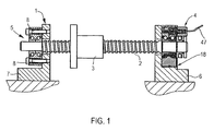
- Fig. 1 describes a bearing assembly 1 according to the invention, comprising a threaded spindle 2, on which in a known manner a threaded nut 3 runs, which, when the bearing assembly is a part of a machine tool, is connected to an axially moving tool element or the like.
- the threaded spindle 2 is mounted in two rolling bearings 4, 5, which are arranged on a respective bearing block 6, 7, at both ends.
- the rolling bearing 5, here a double row angular contact ball bearings, is designed as a pure fixed bearing, it is screwed by screw 8 fixed to the bearing block 7.
- the rolling bearing 4 is designed as a reversible between a property as a fixed bearing and a property as a movable bearing bearing, including the rolling bearing 4, which will be discussed below, is radially deformable to bring it into frictional engagement with the bearing block 6.
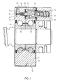
- the Fig. 2 and 3 show in each enlarged sectional views of the rolling bearing 4 Fig.1 ( Fig. 2 ) and a further enlarged partial section of the rolling bearing ( Fig. 3 ).
- the rolling bearing 4 consists of an inner ring 9, which is firmly seated on the threaded spindle 2. About two rows of balls 10, the outer ring 11 is rotatably mounted, the embodiment shown here is designed as angular contact ball bearings. Nevertheless, of course, any other types of storage can be used.
- a pressure chamber 12 is realized on the outer ring 11, a pressure chamber 12 is realized. This is defined by the inner surface 13 of a membrane 14, here a ring made of a thin metal sheet, and the outer contour of the bearing outer ring.
- a helical circumferential groove 15 is formed, which runs along its outer side. This groove 15 is covered by the inner surface 13 of the membrane 14.
- a fluid can be pressed under high pressure into this groove 15, with the diaphragm 14 bulging radially outward given sufficient fluid pressure. The fluid can then also flow out of the groove 15 under the membrane inner surface 13.
- the membrane 14 is peripherally fixedly connected to the bearing outer ring, if appropriate 16 may be provided in corresponding receptacles sealing means.
- the design of the outer ring 11 with the pressure chamber 12 can be taken directly on the radial, axial and tilting stiffness in particular on the wall thickness and guide lengths directly.
- the design of solid webs 19, to which the membrane 14 is attached, at the end faces of the outer ring 11 is advantageous.
- the entire bearing width is used for the guide length in the bearing seat.
- the tilting rigidity can be further increased by increasing the wall thickness of the membrane 14 in the central region, so that the membrane 14 is braced uniformly in the bearing block 6 or on the abutment surface 18.
- Radial forces resulting from the operation are conducted via the webs 19 described in the outer ring 11 into the bearing block 6, while the axial operating loads are dissipated via the frictional engagement generated on the membrane surface 17.
- the design of the pressure chamber 12, in particular its geometric dimensions, depends on the height of the required axial holding forces and thus the necessary radial clamping forces.
- the volume in the pressure chamber 12 is to be kept small in comparison to the chamber length and the outer diameter of the overall construction in order to achieve a high hydraulic rigidity. This is taken into account in the illustrated embodiment by a small chamber height and the design of the membrane, which bulges in operation only around maneuverable micrometer to the outside and is therefore included in a very accurate fit in the bearing block 6.
- the contact surface between the webs 19 and the elastic membrane 14 may be designed as a component pairing with static seal or a cohesive connection (welding, soldering or adhesive bond).
- the concrete realization ultimately depends on the forces to be transmitted, the given applications and any constructional peculiarities.
- a pressure medium via a substantially radially extending feed channel 20, which is fed via a hollow cylindrical, a plurality of chambers forming cylinder-like receptacle 21.
- a piston 23 is received axially movable.
- the receptacle 21 is divided into three individual chambers.
- a first chamber 24 is realized in a component 25, which has corresponding connection means, not shown in greater detail, for a supply line of the pressure medium, and which is fastened separately on the outer ring 11.
- a first recess 26 is realized with a larger diameter, followed by a second recess 27 of smaller diameter.
- a holding and guiding element 28 for example a plastic component, which serves to hold and guide the axially movable piston 23.
- the inner diameter of this holding and guiding element 28 substantially corresponds to the outer diameter of the piston 23 at its end associated with the first chamber 24. Via a projection 29, the holding and guiding element 28 is constricted at the other end, in this area, the piston 23 is guided with its narrower elongated portion.
- the piston guide is in each case sealed, for this purpose corresponding sealing elements 30, 31 are provided, which are provided on the holding and guiding element 28.
- a third chamber 32 is realized, which will be discussed below, and which serves as a collection chamber for any leakage fluid.
- a second chamber 33 is realized, which is the high-pressure chamber while the chamber 24 is the low pressure chamber. From the chamber 33, the supply channel 20 branches off into the region of the pressure chamber 15, or this supply channel 20 ultimately forms part of the pressure chamber.
- the piston 23 has a passage, with a channel portion 34 of larger diameter, which opens into a piston 23 finally passing through the continuing channel portion 35 of smaller diameter.
- the diameter change is required for the integration of a check valve to be described later.
- the pressure medium which is supplied into the first chamber 24, in the second chamber 33 and from there into the pressure chamber 15 pass.
- the available fluid pressure of a hydraulic supply of a machine tool is about 60 bar, this pressure is sometimes not sufficient to bring the membrane 14 in the required frictional engagement in the bearing block 6.
- the piston 23 is also mounted at both ends via spring elements 37, 38 against corresponding restoring forces. While the spring element 37, in this case the coil spring, is supported on an end-face contact surface 41, the spring element 38, also embodied as a helical spring, is received in a corresponding recess 42 on the piston end ,
- a check valve 43 On the piston 23 in the region of the first chamber 24 facing the end of a check valve 43 is further integrated, consisting of a spring element 44, here in the form of a coil spring, and a closing element 45, here in the form of a ball in the closed position in a sealing seat 46 is received, or is there.
- a spring element 44 here in the form of a coil spring
- a closing element 45 here in the form of a ball in the closed position in a sealing seat 46 is received, or is there.
- the hydraulic pressure medium into the first chamber 24, it flows against the piston 23 and opens at sufficient pressure, the check valve 43.
- the fluid then flows further through the diameter of the strong reduced passageway portion 35 in the region of the second high pressure chamber 33 and from below the diaphragm 14 until the equilibrium pressure is set, the check valve closes and the piston moves, the diaphragm buckles.
- the piston 23 in the Fig. 3 shown bearing position moves to the left, ie, it moves into the second chamber 33 into it.
- the membrane 14 bulges outwards and braces the rolling bearing in the bearing block 6, which is then connected as a fixed bearing.
- the check valve 43 prevents backflow, so that it remains at the fixed tension as long as the fluid pressure is present.
- the check valve 43 also has the task, in the absence of pressure of the hydraulic connection on the low pressure side, ie in the first chamber 24, to release a volume flow into the high pressure chamber, if there had been a volume reduction, for example as a result of cooling.
- the check valve opens and a compensating medium flow flows from the first chamber 24 into the second chamber 33 until the pressure difference between the two chambers is smaller than the closing pressure of the check valve.
- the check valve 43 then seals again, the equilibrium position of the piston 23 is reached.
- pressure medium is supplied with the pressure given by the machine-side hydraulic system, for example of 60 bar. This occurs when a signal "terminals of the bearing" was previously given, that is, if the previously switched as a floating bearing is to be clamped as a fixed bearing.
- the piston 23 then shifts against the left spring element 38 due to the compressibility of the hydraulic medium, the increase in volume of the diaphragm construction and any leaks to the left until an equilibrium of forces is established on the piston.
- the pressure in the high-pressure chamber 33 and thus also in the pressure chamber 12 in the case of an assumed transmission ratio of 4 is 240 bar. If the hydraulic supply is depressurized (ie a signal "release of the bearing” is given, ie the bearing is to be switched from the fixed bearing back to a floating bearing), then a pressure of 0 bar is applied to the hydraulic connection. As a result of the even higher pressure in the pressure chamber 12 and the high-pressure chamber 33, the piston 23 moves back to the right against the spring element 37 in the starting position, ie the defined center position.
- an overflow channel 48 is provided in the third chamber 32, via which leakage fluid accumulating in the third chamber 32 can be discharged into the region between the rolling bearing 10. Leakage leaking hydraulic oil can be dissipated in this way and used to lubricate the WälzANDes. At the same time, the overflow channel 16 also ensures the required state of depressurization in the third chamber 32.
- Fig. 4 shows a sectional view similar to that according to Fig. 3
- a second embodiment of a bearing assembly according to the invention in a partial view The embodiment corresponds to that extent according to the embodiment described above, but here no spring element is provided in the low pressure chamber, such is not essential here.
- a device 48 for positive opening of the check valve 43 This device 48 comprises a base 49 axially projecting mandrel 50.
- Fig. 5 shows a sectional view through a non-inventive, to be installed as a separate component device 51, which is integrated into a hydraulic fluid, for example, a pressure line leading to a bearing assembly having only a flexible membrane and pressure chamber, but no integrated pressure booster, such as the previously described embodiment. Rather, the pressure increase takes place via the in Fig. 5
- This device consists of a housing 52 comprising two housing parts 53, 54 which are screwed together.
- a holding and guiding element 56 is inserted in a cylindrical projection 55, in which a piston 57 is guided, which in turn has a through-channel with two channel sections 58, 59.
- a check valve 69 is arranged, the means 60 together with a mandrel 61 for Forced opening is connected upstream.
- the piston is mounted on a compression spring 62, the spring on the other side of the piston is not essential here.
- corresponding sealing means 63, 64 it is sealed in the holding and guiding element 56 out.
- an inlet 65 for example, hydraulic oil is conveyed into the first chamber 66, from there it first exits by forcing the closing ball of the check valve 69 back into the through-channel and on the other side of the piston into the second chamber 67 until the check valve closes, then shifts the piston and translates the pressure.
- the corresponding Hydraulikzu- and -ableitonne be connected via suitable plug or screw to the inlet 65 and the drain 68.
- the operating principle here is the same as described in the embodiments described above, but this is a separate device to be installed. After the device is installed separately and therefore not arranged in the area of a rolling bearing, a third chamber is not essential here. But it can also in this case for receiving and discharging leakage oil z. B. may be provided in a collecting container.
Landscapes
- Engineering & Computer Science (AREA)
- General Engineering & Computer Science (AREA)
- Mechanical Engineering (AREA)
- Rolling Contact Bearings (AREA)
Claims (8)
- Agencement de palier comprenant un arbre, qui est monté à rotation dans deux paliers à roulement disposés dans des supports de paliers, dont un premier est réalisé sous forme de palier fixe, caractérisé en ce que le deuxième palier à roulement (4) présente au moins une chambre de pression (12) pouvant être remplie d'un fluide sous pression, limitée radialement vers l'extérieur par une membrane élastique (14), laquelle membrane (14) se courbe radialement vers l'extérieur lorsqu'une pression est appliquée dans la chambre de pression (12) et se reforme élastiquement en l'absence de pression, de telle sorte que le palier à roulement (4) puisse être serré dans un support de palier (6) pour la fixation axiale et dans l'état non serré, puisse être déplacé axialement, un dispositif (22) pour augmenter la pression du fluide sous pression acheminé étant monté en amont de la chambre de pression (12).
- Agencement de palier selon la revendication 1, caractérisé en ce que la chambre de pression (12) et le dispositif (22) sont prévus directement sur une bague extérieure (11) du palier à roulement (4), ou en ce que la chambre de pression (12) et le dispositif (22) sont prévus sur une bague de pression posée sur la bague extérieure (11) du palier à roulement (4) et raccordée de manière solidaire en rotation avec celui-ci.
- Agencement de palier selon la revendication 2, caractérisé en ce que sur le côté extérieur de la bague extérieure (11) ou de la bague de pression est prévue une rainure périphérique (15) limitée axialement des deux côtés, qui forme la chambre de pression (12) et qui est en prise par le dessus par la membrane (12), ou en ce que la chambre est formée par une surface d'enveloppe plane de la bague extérieure et une membrane courbée, notamment en forme de U.
- Agencement de palier selon l'une quelconque des revendications précédentes, caractérisé en ce que le dispositif (22) comprend un piston (23) à mouvement linéaire, qui présente un canal de passage (34, 35) pour le fluide sous pression, et qui présente deux surfaces de piston différentes à action hydraulique.
- Agencement de palier selon la revendication 4, caractérisé en ce que le piston est disposé de manière déplaçable dans un logement cylindrique, le logement (21) présentant deux chambres (24, 33), le fluide sous pression acheminé affluant dans une première chambre (24), laquelle chambre (24) est montée en amont du piston (23), et une deuxième chambre (33), dans laquelle s'écoule le fluide sous pression à pression accrue, étant montée en aval du piston (23).
- Agencement de palier selon l'une quelconque des revendications précédentes, caractérisé en ce que le dispositif (22) présente un clapet anti-retour (43) pour permettre une réinjection de fluide hydraulique en cas de chute de pression dans la chambre de pression (12).
- Agencement de palier selon la revendication 6, caractérisé en ce qu'un dispositif (48) est prévu pour l'ouverture forcée du clapet anti-retour (43).
- Agencement de palier selon l'une quelconque des revendications précédentes, caractérisé en ce que la bague extérieure (11) ou la bague de pression et la membrane (14) sont étanchées l'une par rapport à l'autre au moyen d'un élément d'étanchéité ou d'une connexion par liaison de matière.
Applications Claiming Priority (1)
| Application Number | Priority Date | Filing Date | Title |
|---|---|---|---|
| DE102008008855A DE102008008855A1 (de) | 2008-02-13 | 2008-02-13 | Lageranordnung |
Publications (2)
| Publication Number | Publication Date |
|---|---|
| EP2090794A1 EP2090794A1 (fr) | 2009-08-19 |
| EP2090794B1 true EP2090794B1 (fr) | 2011-09-07 |
Family
ID=40491107
Family Applications (1)
| Application Number | Title | Priority Date | Filing Date |
|---|---|---|---|
| EP08172090A Not-in-force EP2090794B1 (fr) | 2008-02-13 | 2008-12-18 | Agencement de palier |
Country Status (2)
| Country | Link |
|---|---|
| EP (1) | EP2090794B1 (fr) |
| DE (1) | DE102008008855A1 (fr) |
Cited By (1)
| Publication number | Priority date | Publication date | Assignee | Title |
|---|---|---|---|---|
| WO2019237468A1 (fr) * | 2018-06-12 | 2019-12-19 | 南通远大精密机械有限公司 | Établi de fraiseuse à rainures à barrette à pointes |
Families Citing this family (5)
| Publication number | Priority date | Publication date | Assignee | Title |
|---|---|---|---|---|
| DE102017004994A1 (de) * | 2017-05-17 | 2018-11-22 | Michael Weinig Ag | Gegenlager für Bearbeitungsspindeln von Bearbeitungsmaschinen und Verfahren zum Spannen von Gegenlagern und Werkzeugen |
| CN107084198B (zh) * | 2017-06-06 | 2022-10-18 | 湖南美蓓达科技股份有限公司 | 一种便于加润滑油的轴承 |
| DE102021107749A1 (de) | 2021-03-26 | 2022-09-29 | Matthews International GmbH | Vorrichtung zur Herstellung einer lösbaren Spielfreistellung eines Wälzlagers sowie ein entsprechendes Verfahren |
| DE102021113993A1 (de) | 2021-05-31 | 2022-05-12 | Schaeffler Technologies AG & Co. KG | Hydraulische Spannvorrichtung |
| CN117961583B (zh) * | 2023-12-28 | 2026-02-13 | 中国机械总院集团海西(福建)分院有限公司 | 液体静压转台及机床 |
Family Cites Families (7)
| Publication number | Priority date | Publication date | Assignee | Title |
|---|---|---|---|---|
| DE1745866U (de) * | 1956-04-14 | 1957-05-29 | Siemens Ag | Anordnung zur einstellung des radialspieles eines waelzlagers. |
| SE423566B (sv) * | 1973-01-25 | 1982-05-10 | Foerenade Fabriksverken | Tryckmedieunderstott friktionsorgan for sammankoppling av atminstone tva detaljer foretredesvis for vridmomentoverforing |
| FR2395442A1 (fr) * | 1977-06-21 | 1979-01-19 | Dba | Conjoncteur-disjoncteur hydraulique |
| US4328671A (en) * | 1980-05-12 | 1982-05-11 | Pattison Jack E | Fluid pressure intensifier |
| JPH0265940A (ja) | 1988-08-31 | 1990-03-06 | Okuma Mach Works Ltd | 送りねじの支持構造 |
| DE102004062320B4 (de) | 2004-12-20 | 2007-01-11 | Klimke, Wolfgang, Dr.-Ing. | Lageranordnung |
| DE102007054378A1 (de) | 2007-11-14 | 2009-05-20 | Schaeffler Kg | Lageranordnung |
-
2008
- 2008-02-13 DE DE102008008855A patent/DE102008008855A1/de not_active Withdrawn
- 2008-12-18 EP EP08172090A patent/EP2090794B1/fr not_active Not-in-force
Cited By (1)
| Publication number | Priority date | Publication date | Assignee | Title |
|---|---|---|---|---|
| WO2019237468A1 (fr) * | 2018-06-12 | 2019-12-19 | 南通远大精密机械有限公司 | Établi de fraiseuse à rainures à barrette à pointes |
Also Published As
| Publication number | Publication date |
|---|---|
| EP2090794A1 (fr) | 2009-08-19 |
| DE102008008855A1 (de) | 2009-08-20 |
Similar Documents
| Publication | Publication Date | Title |
|---|---|---|
| EP2090794B1 (fr) | Agencement de palier | |
| EP2299141B1 (fr) | Dispositif de freinage et/ou de serrage doté d'un corps central à forme rigide | |
| WO2007134815A1 (fr) | Système de paliers et valve doseuse et dispositif d'aspiration associés | |
| EP1179149B1 (fr) | Dispositif d'etancheite pour un piston soumis a l'action d'un fluide sous pression dans un cylindre de travail | |
| DE102017121294A1 (de) | Spindeleinheit für Werkzeugmaschinen | |
| DE102018205862A1 (de) | Getriebe, insbesondere für eine Einzelradantriebseinheit | |
| WO2005052382A1 (fr) | Dispositif d'entrainement | |
| DE19957508C1 (de) | Vorrichtung zum Fügen von Fügeteilen auf Hohlprofile mittels fluidischen Innenhochdruckes | |
| EP3242017B2 (fr) | Multiplicateur de pression en tant que visseuse | |
| EP4334619B1 (fr) | Joint tournant pour fluides multiples | |
| EP1936208B1 (fr) | Dispositif de levage actionné par pression fluidique avec un axe fileté autobloquant | |
| EP2008748A2 (fr) | Mandrin à pince de serrage | |
| DE1966073B2 (de) | Druckmittelübertrager an einer Werkzeugmaschine o.dgl | |
| EP3439789B1 (fr) | Buse rotative à haute pression | |
| DE102019217049A1 (de) | Innenzahnradmaschine mit hydrostatisch abgestütztem inneren Dichtungsteil am Füllstück | |
| DE102010005537A1 (de) | Axial verspanntes Wälzlager | |
| EP0761968A1 (fr) | Soupape pour moteur à engrenage à denture intérieure avec palier hydrostatique | |
| WO2018197521A1 (fr) | Unité d'étanchéité | |
| DE102007054378A1 (de) | Lageranordnung | |
| DE2726923A1 (de) | Expandierbare antriebswelle, insbesondere fuer werkzeuge | |
| EP0574682B1 (fr) | Accouplement à friction d'un arbre avec un élément de machine | |
| DE102022201361B4 (de) | Linearaktuator mit hydrostatischer Gewindemutter und hybrider Axiallagerung | |
| DE102007054180A1 (de) | Lageranordnung | |
| DE10125154A1 (de) | Vorrichtung zum lösbaren Halten eines Werkzeuges, Spannhülse und Wälz-und Kugellager | |
| EP0574683B1 (fr) | Accouplement à friction d'un arbre avec un élément de machine |
Legal Events
| Date | Code | Title | Description |
|---|---|---|---|
| PUAI | Public reference made under article 153(3) epc to a published international application that has entered the european phase |
Free format text: ORIGINAL CODE: 0009012 |
|
| AK | Designated contracting states |
Kind code of ref document: A1 Designated state(s): AT BE BG CH CY CZ DE DK EE ES FI FR GB GR HR HU IE IS IT LI LT LU LV MC MT NL NO PL PT RO SE SI SK TR |
|
| AX | Request for extension of the european patent |
Extension state: AL BA MK RS |
|
| 17P | Request for examination filed |
Effective date: 20100219 |
|
| 17Q | First examination report despatched |
Effective date: 20100316 |
|
| AKX | Designation fees paid |
Designated state(s): CH DE FR IT LI |
|
| RAP1 | Party data changed (applicant data changed or rights of an application transferred) |
Owner name: SCHAEFFLER TECHNOLOGIES GMBH & CO. KG |
|
| GRAP | Despatch of communication of intention to grant a patent |
Free format text: ORIGINAL CODE: EPIDOSNIGR1 |
|
| GRAS | Grant fee paid |
Free format text: ORIGINAL CODE: EPIDOSNIGR3 |
|
| GRAA | (expected) grant |
Free format text: ORIGINAL CODE: 0009210 |
|
| REG | Reference to a national code |
Ref country code: CH Ref legal event code: EP |
|
| REG | Reference to a national code |
Ref country code: DE Ref legal event code: R096 Ref document number: 502008004767 Country of ref document: DE Effective date: 20111124 |
|
| RAP2 | Party data changed (patent owner data changed or rights of a patent transferred) |
Owner name: SCHAEFFLER TECHNOLOGIES AG & CO. KG |
|
| REG | Reference to a national code |
Ref country code: CH Ref legal event code: PFA Owner name: SCHAEFFLER TECHNOLOGIES AG & CO. KG Free format text: SCHAEFFLER TECHNOLOGIES GMBH & CO. KG#INDUSTRIESTRASSE 1-3#91074 HERZOGENAURACH (DE) -TRANSFER TO- SCHAEFFLER TECHNOLOGIES AG & CO. KG#INDUSTRIESTRASSE 1-3#91074 HERZOGENAURACH (DE) |
|
| REG | Reference to a national code |
Ref country code: DE Ref legal event code: R097 Ref document number: 502008004767 Country of ref document: DE |
|
| PLBE | No opposition filed within time limit |
Free format text: ORIGINAL CODE: 0009261 |
|
| STAA | Information on the status of an ep patent application or granted ep patent |
Free format text: STATUS: NO OPPOSITION FILED WITHIN TIME LIMIT |
|
| 26N | No opposition filed |
Effective date: 20120611 |
|
| REG | Reference to a national code |
Ref country code: DE Ref legal event code: R097 Ref document number: 502008004767 Country of ref document: DE Effective date: 20120611 |
|
| REG | Reference to a national code |
Ref country code: DE Ref legal event code: R081 Ref document number: 502008004767 Country of ref document: DE Owner name: SCHAEFFLER TECHNOLOGIES AG & CO. KG, DE Free format text: FORMER OWNER: SCHAEFFLER TECHNOLOGIES GMBH & CO. KG, 91074 HERZOGENAURACH, DE Effective date: 20120828 Ref country code: DE Ref legal event code: R081 Ref document number: 502008004767 Country of ref document: DE Owner name: SCHAEFFLER TECHNOLOGIES GMBH & CO. KG, DE Free format text: FORMER OWNER: SCHAEFFLER TECHNOLOGIES GMBH & CO. KG, 91074 HERZOGENAURACH, DE Effective date: 20120828 |
|
| REG | Reference to a national code |
Ref country code: DE Ref legal event code: R081 Ref document number: 502008004767 Country of ref document: DE Owner name: SCHAEFFLER TECHNOLOGIES AG & CO. KG, DE Free format text: FORMER OWNER: SCHAEFFLER TECHNOLOGIES AG & CO. KG, 91074 HERZOGENAURACH, DE Effective date: 20140214 Ref country code: DE Ref legal event code: R081 Ref document number: 502008004767 Country of ref document: DE Owner name: SCHAEFFLER TECHNOLOGIES GMBH & CO. KG, DE Free format text: FORMER OWNER: SCHAEFFLER TECHNOLOGIES AG & CO. KG, 91074 HERZOGENAURACH, DE Effective date: 20140214 |
|
| REG | Reference to a national code |
Ref country code: CH Ref legal event code: PFUS Owner name: SCHAEFFLER TECHNOLOGIES GMBH AND CO. KG, DE Free format text: FORMER OWNER: SCHAEFFLER TECHNOLOGIES AG AND CO. KG, DE |
|
| REG | Reference to a national code |
Ref country code: CH Ref legal event code: PFA Owner name: SCHAEFFLER TECHNOLOGIES AG AND CO. KG, DE Free format text: FORMER OWNER: SCHAEFFLER TECHNOLOGIES GMBH AND CO. KG, DE |
|
| REG | Reference to a national code |
Ref country code: DE Ref legal event code: R081 Ref document number: 502008004767 Country of ref document: DE Owner name: SCHAEFFLER TECHNOLOGIES AG & CO. KG, DE Free format text: FORMER OWNER: SCHAEFFLER TECHNOLOGIES GMBH & CO. KG, 91074 HERZOGENAURACH, DE Effective date: 20150402 |
|
| REG | Reference to a national code |
Ref country code: FR Ref legal event code: PLFP Year of fee payment: 8 |
|
| REG | Reference to a national code |
Ref country code: FR Ref legal event code: PLFP Year of fee payment: 9 |
|
| REG | Reference to a national code |
Ref country code: FR Ref legal event code: PLFP Year of fee payment: 10 |
|
| PGFP | Annual fee paid to national office [announced via postgrant information from national office to epo] |
Ref country code: FR Payment date: 20171226 Year of fee payment: 10 |
|
| PGFP | Annual fee paid to national office [announced via postgrant information from national office to epo] |
Ref country code: CH Payment date: 20171221 Year of fee payment: 10 |
|
| PGFP | Annual fee paid to national office [announced via postgrant information from national office to epo] |
Ref country code: IT Payment date: 20171222 Year of fee payment: 10 |
|
| REG | Reference to a national code |
Ref country code: CH Ref legal event code: PL |
|
| PG25 | Lapsed in a contracting state [announced via postgrant information from national office to epo] |
Ref country code: IT Free format text: LAPSE BECAUSE OF NON-PAYMENT OF DUE FEES Effective date: 20181218 Ref country code: FR Free format text: LAPSE BECAUSE OF NON-PAYMENT OF DUE FEES Effective date: 20181231 |
|
| PG25 | Lapsed in a contracting state [announced via postgrant information from national office to epo] |
Ref country code: LI Free format text: LAPSE BECAUSE OF NON-PAYMENT OF DUE FEES Effective date: 20181231 Ref country code: CH Free format text: LAPSE BECAUSE OF NON-PAYMENT OF DUE FEES Effective date: 20181231 |
|
| PGFP | Annual fee paid to national office [announced via postgrant information from national office to epo] |
Ref country code: DE Payment date: 20200227 Year of fee payment: 12 |
|
| REG | Reference to a national code |
Ref country code: DE Ref legal event code: R119 Ref document number: 502008004767 Country of ref document: DE |
|
| PG25 | Lapsed in a contracting state [announced via postgrant information from national office to epo] |
Ref country code: DE Free format text: LAPSE BECAUSE OF NON-PAYMENT OF DUE FEES Effective date: 20210701 |