EP2009182A2 - Vereinfachtes Fundament und Erdbearbeitungsverfahren damit - Google Patents
Vereinfachtes Fundament und Erdbearbeitungsverfahren damit Download PDFInfo
- Publication number
- EP2009182A2 EP2009182A2 EP08252112A EP08252112A EP2009182A2 EP 2009182 A2 EP2009182 A2 EP 2009182A2 EP 08252112 A EP08252112 A EP 08252112A EP 08252112 A EP08252112 A EP 08252112A EP 2009182 A2 EP2009182 A2 EP 2009182A2
- Authority
- EP
- European Patent Office
- Prior art keywords
- support
- drive
- drive pile
- pile
- roughly
- Prior art date
- Legal status (The legal status is an assumption and is not a legal conclusion. Google has not performed a legal analysis and makes no representation as to the accuracy of the status listed.)
- Withdrawn
Links
- 238000000034 method Methods 0.000 title claims description 17
- 238000010276 construction Methods 0.000 claims abstract description 79
- 239000002689 soil Substances 0.000 claims abstract description 44
- 239000002184 metal Substances 0.000 claims abstract description 11
- PPBRXRYQALVLMV-UHFFFAOYSA-N Styrene Chemical compound C=CC1=CC=CC=C1 PPBRXRYQALVLMV-UHFFFAOYSA-N 0.000 claims description 8
- 239000006260 foam Substances 0.000 claims description 4
- 230000014759 maintenance of location Effects 0.000 description 26
- 238000012360 testing method Methods 0.000 description 15
- 230000007774 longterm Effects 0.000 description 12
- 238000006243 chemical reaction Methods 0.000 description 6
- 230000008878 coupling Effects 0.000 description 6
- 238000010168 coupling process Methods 0.000 description 6
- 238000005859 coupling reaction Methods 0.000 description 6
- 238000003466 welding Methods 0.000 description 6
- 238000005304 joining Methods 0.000 description 4
- 238000005259 measurement Methods 0.000 description 3
- 230000015556 catabolic process Effects 0.000 description 2
- 230000006378 damage Effects 0.000 description 2
- 238000006731 degradation reaction Methods 0.000 description 2
- 238000006073 displacement reaction Methods 0.000 description 2
- 230000007613 environmental effect Effects 0.000 description 2
- 239000002023 wood Substances 0.000 description 2
- 208000019901 Anxiety disease Diseases 0.000 description 1
- 229910000831 Steel Inorganic materials 0.000 description 1
- 230000036506 anxiety Effects 0.000 description 1
- 238000009435 building construction Methods 0.000 description 1
- 238000000151 deposition Methods 0.000 description 1
- 230000000694 effects Effects 0.000 description 1
- 230000002708 enhancing effect Effects 0.000 description 1
- 238000004519 manufacturing process Methods 0.000 description 1
- 239000000463 material Substances 0.000 description 1
- 239000007769 metal material Substances 0.000 description 1
- 238000012986 modification Methods 0.000 description 1
- 230000004048 modification Effects 0.000 description 1
- 238000003825 pressing Methods 0.000 description 1
- 238000012545 processing Methods 0.000 description 1
- 238000007493 shaping process Methods 0.000 description 1
- 239000010959 steel Substances 0.000 description 1
- 239000000126 substance Substances 0.000 description 1
- 238000012546 transfer Methods 0.000 description 1
- 238000013519 translation Methods 0.000 description 1
Images


Classifications
-
- E—FIXED CONSTRUCTIONS
- E02—HYDRAULIC ENGINEERING; FOUNDATIONS; SOIL SHIFTING
- E02D—FOUNDATIONS; EXCAVATIONS; EMBANKMENTS; UNDERGROUND OR UNDERWATER STRUCTURES
- E02D27/00—Foundations as substructures
- E02D27/32—Foundations for special purposes
-
- E—FIXED CONSTRUCTIONS
- E02—HYDRAULIC ENGINEERING; FOUNDATIONS; SOIL SHIFTING
- E02D—FOUNDATIONS; EXCAVATIONS; EMBANKMENTS; UNDERGROUND OR UNDERWATER STRUCTURES
- E02D5/00—Bulkheads, piles, or other structural elements specially adapted to foundation engineering
- E02D5/74—Means for anchoring structural elements or bulkheads
- E02D5/80—Ground anchors
-
- E—FIXED CONSTRUCTIONS
- E02—HYDRAULIC ENGINEERING; FOUNDATIONS; SOIL SHIFTING
- E02D—FOUNDATIONS; EXCAVATIONS; EMBANKMENTS; UNDERGROUND OR UNDERWATER STRUCTURES
- E02D5/00—Bulkheads, piles, or other structural elements specially adapted to foundation engineering
- E02D5/22—Piles
- E02D5/24—Prefabricated piles
-
- E—FIXED CONSTRUCTIONS
- E02—HYDRAULIC ENGINEERING; FOUNDATIONS; SOIL SHIFTING
- E02D—FOUNDATIONS; EXCAVATIONS; EMBANKMENTS; UNDERGROUND OR UNDERWATER STRUCTURES
- E02D5/00—Bulkheads, piles, or other structural elements specially adapted to foundation engineering
- E02D5/22—Piles
- E02D5/52—Piles composed of separable parts, e.g. telescopic tubes ; Piles composed of segments
-
- E—FIXED CONSTRUCTIONS
- E04—BUILDING
- E04H—BUILDINGS OR LIKE STRUCTURES FOR PARTICULAR PURPOSES; SWIMMING OR SPLASH BATHS OR POOLS; MASTS; FENCING; TENTS OR CANOPIES, IN GENERAL
- E04H12/00—Towers; Masts or poles; Chimney stacks; Water-towers; Methods of erecting such structures
- E04H12/22—Sockets or holders for poles or posts
- E04H12/2207—Sockets or holders for poles or posts not used
- E04H12/2215—Sockets or holders for poles or posts not used driven into the ground
- E04H12/223—Sockets or holders for poles or posts not used driven into the ground with movable anchoring elements; with separately driven anchor rods
-
- E—FIXED CONSTRUCTIONS
- E02—HYDRAULIC ENGINEERING; FOUNDATIONS; SOIL SHIFTING
- E02D—FOUNDATIONS; EXCAVATIONS; EMBANKMENTS; UNDERGROUND OR UNDERWATER STRUCTURES
- E02D2300/00—Materials
- E02D2300/0026—Metals
Definitions
- the present invention relates to construction foundations, more particularly simplified foundations using piles, and a groundwork method using the same.
- parks are constructed in green belts, wetlands, marshes, river terraces, and woodlots, by building construction products, such as bridges, sidewalks, steps, fences, benches, tables, and play equipment.
- foundations are important.
- the foundation is formed by excavating the ground, depositing leveling concrete, and injecting freshly-mixed concrete within a framework constructed on the leveling concrete.
- trucks carrying freshly-mixed concrete to enter the above-listed sites, such as green belts.
- such entrance is not preferable even if it is possible, considering that it might destroy the natural environment.
- a construction product becomes unnecessary, it is extremely difficult to remove its concrete foundation. As a result, the concrete foundation remains in the natural environment without being removed, leading to environmental destruction.
- Patent Document 1 proposes a simplified foundation formed by injecting concrete into a cylindrical-, rectangular-, or triangular-columnar form having four guide sleeves inserted therethrough (see, for example, FIG. 4 of Patent Document 1). Piles are driven into the ground through the guide sleeves, so that the form and the piles constitute a foundation for a construction product to be fixed thereon.
- Patent Document 2 proposes a technique for constructing a foundation by driving piles into the ground after inserting the piles into holes provided in brackets each having a U-shaped cross section and being attached to a post (see, for example, FIG. 1 of Patent Document 2).
- Patent Document 2 also proposes brackets each having an H-shaped cross section (see, for example, FIG. 3 of Patent Document 2).
- Patent Document 2 also proposes a simplified foundation including piles driven into a rectangular-columnar construction product (see, for example, FIGS. 8 and 9 of Patent Document 2).
- Patent Document 3 proposes a simplified foundation constructed by inserting piles into a hardened concrete base, and driving the piles into the ground.
- the base has holes for inserting the piles therethrough, and the holes are provided by inserting tapered dowels through upper and lower forms made up of plastic, and injecting concrete into the forms (see, for example, FIG. 2 of Patent Document 3).
- the upper and lower forms and the dowels are removed, and the piles, which are slightly thinner than the holes provided by the dowels, are inserted through the holes and driven into the ground (see, for example, FIG. 3 of Patent Document 3).
- Patent Document 4 proposes a technique for providing a concrete wall foundation.
- sleeves are provided through two opposing footings between which a concrete wall is formed (see, for example, FIGS. 1 and 3 of Patent Document 4). Piles are inserted through the sleeves, and driven into the ground (see, for example, FIG. 3 of Patent Document 4).
- Patent Document 5 discloses a simplified foundation for a green house.
- the simplified foundation of Patent Document 5 includes a head portion formed of concrete blocks, and two or more piles inserted through the head portion. The piles are driven into the ground so that the simplified foundation acts as a base of the green house.
- Patent Document 6 proposes a simplified foundation in which sleeves are attached to a body having upper and lower flanges, and piles are inserted through the sleeves (see, FIG. 1 of Patent Document 6). Moreover, Patent Document 6 also discloses a simplified foundation having its bearing strength enhanced by coupling members for coupling the upper and lower flanges (see, for example, FIGS. 3 , 4, and 5 of Patent Document 6). Furthermore, Patent Document 6 also discloses a securing method which uses the simplified foundation with enhanced bearing strength in combination with anchor bolts (see, for example, FIG. 6 of Patent Document 6).
- FIG. 18 is a perspective view illustrating a simplified foundation disclosed in Japanese Laid-Open Patent Publication No. 2005-299215 (hereinafter, referred to as "Patent Document 7").
- the simplified foundation proposed in Patent Document 7 includes an upper securing plate 900, a lower securing plate 901, and a plurality of sleeves 902 coupled with the upper and lower securing plates 900 and 901, as shown in FIG. 18 (see, for example, FIG. 3 of Patent Document 7). Piles 903 are inserted through the sleeves 902 and driven into the ground, thereby securing the foundation to the ground.
- FIG. 8 of Patent Document 2 shows a horizontally-placed rectangular foundation, which is inconveniently difficult to transport.
- FIG. 9 of Patent Document 2 shows a vertically-placed rectangular-columnar foundation, which is also inconveniently difficult to transfer.
- FIG. 9 of Patent Document 2 dose not describe any specific method for securing the construction product.
- the simplified foundation according to Patent Document 3 also has a problem similar to the problem with the simplified foundation according to Patent Document 1.
- Patent Document 4 The simplified foundation according to Patent Document 4 is applicable only to concrete walls, and is not always applicable to all construction products, including bridges and sidewalks.
- the simplified foundation according to Patent Document 5 has the head portion made up of concrete, and therefore it also has a problem similar to the problem with the simplified foundation according to Patent Document 1.
- Patent Document 6 The simplified foundation according to Patent Document 6 does not use any concrete, but it requires the coupling members for coupling the upper and lower flanges, resulting in a complicated structure.
- Patent Document 6 describes that the coupling members can be secured to the upper and lower flanges not only via bolts but also via welding, which results in a complicated structure as well, and also creates a problem with production cost.
- the construction product imposes load on a cover 904.
- the load on the cover 904 is also applied to the upper securing plate 900.
- the load on the upper securing plate 900 is distributed in the horizontal direction, as well as in the directions of the sleeves 902. Since the upper securing plate 900 is a flat plate, the load distributed in the horizontal direction is smaller than the load distributed in the directions of the sleeves 902. Accordingly, most of the load on the upper securing plate 900 is applied to the sleeves 902. As a result, excessive load might be applied to junctions 905 between the upper securing plate 900 and the sleeves 902, as well as to junctions 906 between the lower securing plate 901 and the sleeves 902. Therefore, the junctions 905 and 906 could be broken after years of use.
- the present invention may provide a simplified foundation that can be readily constructed using as little concrete as possible.
- the present invention may also provide a low-cost simplified foundation capable of withstanding long-term use.
- a simplified foundation made up of metal for supporting a target construction product, including: at least one drive pile to be driven into the soil in an angularly inclined manner; and a support for receiving the drive pile to be inserted therethrough and attaching the target construction product on its upper portion, wherein the support is hollow and bowl-shaped from a part on which to attach the target construction product downwardly toward any part in which to insert the drive pile.
- the support is bowl-shaped from a part on which to attach the target construction product downwardly toward any part in which to insert the drive pile, and therefore it is possible to disperse the load of the target construction product, and enhance the strength of the support. Accordingly, it is possible to provide a simplified foundation without using any concrete.
- the drive pile is driven into the soil through the support, and therefore the simplified foundation of the present invention can function as a piled foundation utilizing a friction force of the drive pile.
- the simplified foundation of the present invention can also directly function as an auxiliary foundation. So long as the drive pile reaches the supporting soil, the resistance of the supporting soil can also contribute to achievement of the piled foundation.
- target construction products such as bridges, sidewalks, steps, fences, benches, tables, and play equipment
- green belt, wetland, marshes, river terraces, or woodlot it is often the case that the ground is soft.
- simplified foundation of the present invention it is possible to support target construction products on such soft ground. Construction on the soft ground is often difficult to perform, and therefore it is necessary to simplify the construction.
- the simplified foundation of the present invention does not use any concrete, and therefore it is lightweight. Accordingly, transportation to construction sites is readily carried out, and there is no need for any concrete mixer trucks to enter the construction sites. Therefore, the construction is readily achieved.
- the simplified foundation of the present invention is made up of metal, and therefore when any target construction product becomes unnecessary, it can be collected and recycled, which advantageously prevents environmental destruction. Furthermore, the simplified foundation of the present invention is entirely made up of metal, and does not use any concrete, and therefore it can be provided at low cost.
- the support may include at least one cylindrical guide member for guiding the drive pile, and the guide member may be disposed in an angularly inclined manner in accordance with an inclination angle of the drive pile, and joined at least to the bowl-shaped portion.
- the guide member and the support are joined at the bowl-shaped portion.
- the load of the target construction product is mostly distributed in the tangential direction of the bowl.
- the load distributed in the movement direction of the guide member becomes smaller than the load distributed in the tangential direction. Therefore, it is possible to minimize the load directly imposed on the guide member to the greatest possible extent.
- the support may be provided in the shape of a hollow, roughly-spherical or roughly-oval-spherical body.
- the support By shaping the support to have such a hollow, roughly-spherical or roughly-oval-spherical body, the support can be bowl-shaped from a part on which to attach the target construction product downwardly toward any part in which to insert the drive pile.
- the hollow, roughly-spherical or roughly-oval-spherical support can be readily produced, thereby making it possible to provide a low-cost simplified foundation.
- the roughly-spherical or roughly-oval-spherical support itself is strong, and therefore it is possible to provide a simplified foundation capable of withstanding long-term use.
- the support may include: a holed portion provided in the upper portion, thereby making it possible to view the inside of the support; an anchor bolt to be inserted from the bottom toward the holed portion; and a lid allowing the anchor bolt to pass therethrough, thereby closing the holed portion.
- the drive pile When inserting the pile to be driven, the drive pile can be driven into an appropriate position by looking into the holed portion.
- the anchor bolt it is possible to confirm the position of the anchor bolt by looking into the holed portion.
- the construction can be readily performed.
- At least a part of the outer rim of the lid may be narrower than at least a part of the inner rim of the holed portion.
- the support may further include an attachment bracket attached to the anchor bolt for securing the target construction product, and the attachment bracket may have a gap for allowing a nut to be tightened on the anchor bolt.
- the anchor bolt and the target construction product can be attached to the attachment bracket.
- the support may further include at least one cylindrical guide member for guiding the drive pile, and the guide member may be disposed in an angularly inclined manner in accordance with the inclination angle of the drive pile, and is joined to either one or both hemispheres of the roughly-spherical or roughly-oval-spherical body.
- the guide member and the support are joined to either one or both hemispheres of the roughly-spherical or roughly-oval-spherical body. That is, the junction is positioned in the bowl-shaped portion of the support. In the bowl-shaped portion, the load of the target construction product is mostly distributed in the tangential direction of the bowl. As a result, the load distributed in the movement direction of the guide member becomes smaller than the load distributed in the tangential direction. Therefore, it is possible to minimize the load directly imposed on the guide member to the greatest possible extent. Thus, it is possible to prevent the junction between the guide member and the support from being broken, thereby making it possible to enhance the strength of the support, resulting in a simplified foundation capable of withstanding long-term use.
- the guide member may be disposed at the same angle as another guide member adjacent thereto.
- the load of the target construction product can be uniformly dispersed to a plurality of drive piles.
- the inclination angle of the guide member may be 40 to 60 degrees with respect to a horizontal plane.
- the drive pile may include at least a set of a cylindrical first drive pile and a second drive pile having an inner diameter smaller than that of the first drive pile, and the second drive pile may be driven into the soil after the first drive pile is driven, through the inside of the cylindrical first drive pile.
- the second drive pile can be driven after driving the first drive pile, so that the load bearing capacity can be enhanced compared to the case where only the first drive pile is driven.
- the second drive pile may be cylindrical
- the simplified foundation may further include a soil-side tip member to be attached to each soil-side tip of the first and second piles when driving the first and second drive piles, the soil-side tip member including a first protrusion smaller than the inner diameter of the first drive pile, and a second protrusion smaller than the inner diameter of the second drive pile.
- the support may include at least one cylindrical guide member for guiding the first and second drive piles
- the second drive pile may be cylindrical
- the simplified foundation may further include a hammering-side tip member with a tip having a diameter larger than the inner diameter of the guide member.
- first and second drive piles when driving the first and second drive piles, it is possible to protect their hammering-side tips.
- the first and second drive piles can be readily hammered.
- the simplified foundation may further include a cap member attached to the hammering-side tip of the first drive pile.
- the support may include upper and lower supporting portions separable from each other, the upper and lower supporting portions being joined when being installed in the soil.
- the simplified foundation can be readily constructed.
- a support separable into upper and lower portions is used to further facilitate easy construction of the simplified foundation.
- the present invention is also directed to a simplified foundation made up of metal for supporting a target construction product, including: at least one drive pile to be driven into the soil in an angularly inclined manner; a support for receiving the drive pile to be inserted therethrough and attaching the target construction product on its upper portion, the support being provided in the shape of a roughly-spherical or roughly-oval-spherical body; and at least one cylindrical guide member disposed in an angularly inclined manner in accordance with an inclination angle of the drive pile for guiding the drive pile joined to either one or both hemispheres of the roughly-spherical or roughly-oval-spherical support, wherein the support has styrene foam embedded in at least a portion thereof.
- the buoyancy of the styrene foam prevents settlement of the simplified foundation.
- the present invention is also directed to a simplified foundation made up of metal for supporting a target construction product, including: at least one drive pile to be driven into the soil in an angularly inclined manner; a support for receiving the drive pile to be inserted therethrough and attaching the target construction product on its upper portion, the support being provided in the shape of a roughly-spherical or roughly-oval-spherical body; and at least one cylindrical guide member disposed in an angularly inclined manner in accordance with an inclination angle of the drive pile for guiding the drive pile joined to an upper or lower hemisphere of the roughly-spherical or roughly-oval-spherical support, wherein the support has concrete injected into at least a portion thereof.
- the support has an enhanced load bearing capacity.
- the present invention is also directed to a simplified foundation made up of metal for supporting a target construction product, including: at least one drive pile to be driven into the soil in an angularly inclined manner; and a support for receiving the drive pile to be inserted therethrough and attaching the target construction product on its upper portion, the support being provided in the shape of a roughly-spherical or roughly-oval-spherical body that can be separated into upper and lower portions, wherein the support has concrete injected into at least the lower portion of the separable roughly-spherical or roughly-oval-spherical body.
- the present invention is also directed to a groundwork method for constructing a foundation for a target construction product, including the steps of: installing a hollow support being bowl-shaped from a part on which to attach the target construction product downwardly toward any part in which to insert the drive pile; and driving the drive pile into the soil after inserting the drive pile into a holed portion provided in the support.
- the step of driving the drive pile into the soil may include inserting the drive pile through a cylindrical guide member joined at least to the bowl-shaped portion of the support so as to be inclined in accordance with an inclination angle of the drive pile, thereby driving the drive pile into the soil.
- the drive pile may include at least a set of a cylindrical first drive pile and a second drive pile having an inner diameter smaller than that of the first drive pile, and the second drive pile may be driven into the soil after the first drive pile is driven, through the inside of the cylindrical first drive pile.
- the support may be provided in the shape of a roughly-spherical or roughly-oval-spherical body that can be separated into upper and lower portions, and the step of installing the support may include coupling the lower hemisphere of the roughly-spherical or roughly-oval-spherical body to the upper hemisphere of the roughly-spherical or roughly-oval-spherical body before installing the support.
- the present invention uses a hollow, bowl-shaped support provided in the shape of, for example, a roughly-spherical or roughly-oval-spherical body, thereby making it possible to provide a simplified foundation that has a strong load bearing capacity and can be readily constructed without using any concrete.
- the guide member for guiding the drive pile is joined to the bowl-shaped portion, thereby preventing the junction between the guide member and the support from being broken, and further enhancing the strength of the support.
- the simplified foundation can withstand long-term use.
- by using the first and second drive piles it is possible to enhance the load bearing capacity.
- the soil-side tip member When driving the first and second drive piles, the soil-side tip member is used to lower the point at which to hammer the second drive pile, thereby facilitating ease of work.
- the first and second drive piles can be readily hammered.
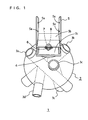
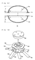
- FIG. 1 is a perspective view illustrating the structure of a simplified foundation 1 according to a first embodiment of the present invention.
- the simplified foundation 1 is made up of metal, and is intended for supporting a construction product to be supported thereon.
- the simplified foundation 1 includes a support 2, a lid 4, an attachment bracket 5, a washer 6, a nut 7, and an anchor bolt 8, as shown in FIG. 1 .
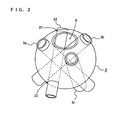
- FIG. 2 is a perspective view illustrating the structure of the support 2.
- FIG. 3 is a front view illustrating the structure of the support 2.
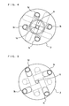
- FIG. 4 is a top view illustrating the structure of the support 2.
- FIG. 5 is a bottom view illustrating the structure of the support 2.
- the support 2 includes guide members 3a, 3b, 3c, and 3d, and a holed portion 9.
- the support 2 is provided in the form of a hollow, roughly-spherical body.
- the guide members 3a, 3b, 3c, and 3d are cylindrical pipes for guiding first drive piles 10a, 10b, 10c, and 10d, respectively (see FIG. 7 to be described later).
- the first drive piles 10a, 10b, 10c, and 10d are driven into the soil in an angularly inclined manner.
- the guide members 3a, 3b, 3c, and 3d are angularly disposed in accordance with the inclination angle of the first drive piles 10a, 10b, 10c, and 10d.
- the support 2 has holes provided therein to accord with the guide members 3a, 3b, 3c, and 3d, which are inserted through the holes, and joined at contact points with the support 2 in the upper hemisphere (for example, U1 shown in FIG. 2 ) and the lower hemisphere (for example, U2 shown in FIG. 2 ) of the roughly-spherical support 2.
- any well-known method such as welding or bolting, can be used.
- the holed portion 9 is provided at the top of the support 2, thereby making it possible to view the inside of the support 2.
- the holed portion 9 can be closed with the lid 4.
- the anchor bolt 8 can be inserted into a hole 10 at the bottom of the support 2.
- the lid 9 has provided therein a hole for allowing the anchor bolt 8 to pass therethrough (a hole 4a shown in FIG. 6 to be described later).
- the attachment bracket 5 is fitted on the anchor bolt 8 projecting from the hole 4a.
- the attachment bracket 5 is secured on the lid 4 via the washer 6 and the nut 7.
- the attachment bracket 5 includes a plurality of holes 5a for securing the target construction product, for example, via bolts or screws.
- the guide member 3b is disposed, extending from the upper hemisphere of the spherical support 2 to the lower hemisphere at an inclination angle ⁇ with respect to the horizontal plane, as shown in FIG. 3 .
- the guide members 3a, 3c, and 3d are similarly disposed, extending from the upper hemisphere of the spherical support 2 to the lower hemisphere at the inclination angle ⁇ .
- the angle between the guide members 3a and 3b is, for example, 80 degrees, as shown in FIG. 3 .
- the inclination angle ⁇ is set to 50 degrees.
- the inclination angle ⁇ is preferably set within the range from 40 to 60 degrees, but is not limited to such a range.
- the guide members 3a, 3b, 3c, and 3d When projecting the guide members 3a, 3b, 3c, and 3d in the direction toward the top or bottom surface, the guide members 3a, 3b, 3c, and 3d are disposed such that sets of adjacent guide members are uniformly angled, as can be appreciated from FIGS. 4 and 5 .
- the adjacent guide members may be disposed at an angle of 90 degrees. As a result, the load of the target construction product is uniformly dispersed.
- the guide members 3a, 3b, 3c, and 3d are disposed so as to keep out of the path of the anchor bolt 8, so that the anchor bolt 8 inserted into the hole 10 can reach the holed portion 9, as shown in FIG. 4 .
- the inside of the support 2 can be viewed from the holed portion 9. Accordingly, the anchor bolt 8 can be readily inserted.
- FIG. 6 is an enlarged cross-sectional view illustrating the structures of the holed portion 9 and the lid 4 of the support 2.
- the lid 4 is formed to have a stepped cross section as could be embodied by placing a large- and a small-sized disk on each other.
- the holed portion 9 has a stepped cross section with a top opening larger than a bottom opening.
- the holed portion 9 and the lid 4 are sized to create gaps 4b and 4c when placing the lid 4 on the holed portion 9, as shown in FIG. 6 .
- gaps can be created by configuring the lid 4 and the holed portion 9 such that at least a part of the outer rim of the lid 4 is narrower than at least a part of the inner rim of the holed portion 9.
- the attachment bracket 5 includes a bottom plate 5c and a top plate 5b, as shown in FIG. 1 .
- the bottom plate 5c has provided therein a hole in which to insert the anchor bolt 8.
- the top plate 5b acts as a base of the target construction product.
- the anchor bolt 8 is tightened with the nut 7 within a space between the bottom plate 5c and the top plate 5b, so that the nut 7 can be readily loosened.
- FIG. 7 is a front view illustrating the structure of the simplified foundation 1 having the drive piles inserted therethrough.
- the first drive piles 10a, 10b, 10c, and 10d are cylindrical pipes.
- the outer diameter of each of the first drive piles 10a, 10b, 10c, and 10d is smaller than the inner diameter of each of the guide members 3a, 3b, 3c, and 3d.
- the first drive piles 10a, 10b, 10c, and 10d are inserted through the guide members 3a, 3b, 3c, and 3d, respectively, and driven into the soil by a pile driver or a hammer. Note that the first drive piles 10a, 10b, 10c, and 10d and the guide members 3a, 3b, 3c, and 3d may be joined via bolts or welding.
- FIG. 8 is a front view illustrating the structure of the simplified foundation 1, in which the position of the anchor bolt 8 is clearly shown.
- the anchor bolt 8 penetrates upward so as to keep out of contact with the guide members 3a, 3b, 3c, and 3d, as shown in FIG. 8 .
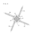
- FIG. 9 is a top view illustrating the positional relationship between the guide members 3a, 3b, 3c, and 3d and the first drive piles 10a, 10b, 10c, and 10d. Since the guide members 3a, 3b, 3c, and 3d are disposed at a uniform angle, the first drive piles 10a, 10b, 10c, and 10d are driven into the soil also at the uniform angle. As a result, the load on the target construction product is dispersed. For example, when there are four guide members as shown in FIG. 9 , the guide members 3a and 3b are disposed so as to be in parallel with each other when they are projected in the direction as shown in the top view.
- the guide members 3c and 3d are also disposed so as to be in parallel with each other when they are projected in the direction as shown in the top view. Furthermore, the guide members 3a and 3b and the guide members 3c and 3d are disposed so as to be perpendicular to each other when they are projected in the direction as shown in the top view. With such an arrangement, the guide members 3a, 3b, 3c, and 3d are disposed at a uniform angle. For example, the guide member 3a penetrates through the spherical body to its bottom so as not to pass immediately below the holes for the guide members 3b and 3c provided in the upper hemisphere of the spherical body.
- the guide members 3b, 3c, and 3d similarly penetrate through the spherical body. In this manner, the holes provided in the spherical body are uniformly arranged at the upper and lower hemispheres of the spherical body, thereby preventing the strength of the spherical body itself from being reduced. Note that the arrangement of the guide members 3a, 3b, 3c, and 3d is not limited to the above.
- FIG. 10 is a view illustrating second drive piles 11a and 11b being driven. Note that in FIG. 10 , the first and second drive piles to be driven through the guide members 3c and 3d are omitted to simplify the figure.
- the first drive pile 10a and the second drive pile 11a are paired.
- the second drive piles 11a and 11b are longer than the first drive piles 10a and 10b.
- the first drive pile 10b and the second drive pile 11b are paired.
- the outer diameter of each of the second drive piles 11a and 11b is smaller than the inner diameter of each of the first drive piles 10a and lOb.
- the second drive piles 11a and 11b are driven through the inside of the cylindrical first drive piles 10a and 10b, respectively.
- the piles for the guide members 3c and 3d are similarly driven into the soil.
- the second drive piles can be driven after the first drive piles when the vertical load bearing capacity and/or the horizontal load bearing capacity are/is not sufficient.
- the first and second drive piles and the guide members 3a, 3b, 3c, and 3d may be joined via bolts or welding, for example. Note that in FIG.
- the second drive piles 11a and 11b are shown to be longer than the first drive piles 10a and 10b, but the second drive piles 11a and 11b may be shorter than the first drive piles 10a and 10b.
- the second drive piles 11a and 11b may be driven by bringing auxiliary piles into contact with the hammering-side ends of the second drive piles 11a and 11b, and pressing the auxiliary piles upon the second drive piles 11a and 11b.
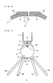
- FIG. 11A is a front view of a soil-side tip member 13 for use in driving each of the first and second drive piles.
- FIG. 11B is a bottom view of the soil-side tip member 13.
- FIG. 11C is a top view of the soil-side tip member 13.
- each second drive pile is cylindrical.
- the soil-side tip member 13 is attached to each of the first and second drive piles at its soil-side tip.
- the tip of the soil-side tip member 13 constitutes an apex 13a.
- the soil-side tip member 13 includes a protrusion 13b having an outer diameter smaller than the inner diameter of each first drive pile, and a protrusion 13c having an outer diameter smaller than the inner diameter of each second drive pile.
- the soil-side tip member 13 Before driving the first drive pile into the soil, the soil-side tip member 13 is initially attached to the tip of the first drive pile, and inserted into the guide member. With the first drive pile being driven into the soil, the soil-side tip member 13 is located at the tip of the first drive pile in the soil. Since the soil-side tip member 13 is located at the tip of the first drive pile, the soil does not enter the first drive pile. Accordingly, when driving the second drive pile into the soil, it is possible to smoothly insert the second drive pile through the tip of the first drive pile. Therefore, even when driving the second drive pile longer than the first drive pile, it is not necessary to set a high hammering point. When the second drive pile is inserted into the first drive pile, the protrusion 13c is placed in the second drive pile. Thereafter, the second drive pile is driven into the soil. In this manner, by using the soil-side tip member 13, it becomes possible to smoothly drive the second drive pile into the soil without setting a high hammering point.
- the protrusions 13b and 13c may be the same.
- the soil-side tip member 13 may have a protrusion extending from the apex 13a and having an outer diameter smaller than the inner diameter of the second drive pile.
- the outer diameter of the protrusion 13b be almost the same as the inner diameter of the first drive pile, and the outer diameter of the protrusion 13c be almost the same as the inner diameter of the second drive pile.
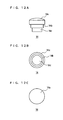
- FIG. 12A is a front view of a hammering-side tip member 14 for use in driving each of the first and second drive piles.
- FIG. 12B is a bottom view of the hammering-side tip member 14.
- FIG. 12C is a top view of the hammering-side tip member 14.
- each second drive pile is cylindrical.
- the hammering-side tip member 14 is attached to each of the first and second drive piles at its hammering-side tip.
- the hammering-side tip member 14 includes a protrusion 14b having an outer diameter smaller than the inner diameter of each first drive pile, and a protrusion 14c having an outer diameter smaller than the inner diameter of each second drive pile.
- the hammering-side tip member 14 is attached to the hammering-side tip of the first drive pile, and the first drive pile is inserted into the guide member.
- the first drive pile is driven into the soil.
- the outer diameter of the tip 14a is larger than the inner diameter of the guide member. Therefore, when driving the first drive pile, the hammering-side tip member 14 is not entirely loaded into the guide member.
- the hammering-side tip member 14 is removed from the guide member. Thereafter, the second drive pile is driven as in the case of the first drive pile. In this manner, since the tip 14a of the hammering-side tip member 14 has the outer diameter larger than the inner diameter of the guide member, it is possible to sequentially drive the first and second drive piles.
- the protrusions 14b and 14c may be the same.
- the hammering-side tip member 14 may have a protrusion extending from the tip 14a and having the outer diameter smaller than the inner diameter of the second drive pile.
- the outer diameter of the protrusion 14b be almost the same as the inner diameter of the first drive pile, and the outer diameter of the protrusion 14c be almost the same as the inner diameter of the second drive pile.
- FIG. 13A is a top view of a cap member 15 to be attached to the hammering-side tip of the first drive pile.
- FIG. 13B is a front view of the cap member 15.
- FIG. 13C is a bottom view of the cap member 15.
- the cap member 15 has a recess 15a roughly the same size as the outer diameter of the first drive pile. The first drive pile is inserted into the recess 15a. Since the cap member 15 is attached to the hammering-side tip of the first drive pile, it is possible to prevent any undesirable substance from entering the first drive pile, thereby preventing degradation of the simplified foundation.
- the first embodiment uses the hollow support 2 into which the drive piles are inserted to construct the foundation. As a result, it is possible to provide a simplified foundation that can be readily constructed without using any concrete. Also, the first embodiment uses the guide members 3a, 3b, 3c, and 3d by which the drive piles are guided, further facilitating ease of construction.
- the support 2 since the support 2 has a roughly-spherical body, the load on the support 2 is distributed in the tangential direction of the spherical surface, and in the central direction of the spherical body.
- the load on the support 2 is distributed in the tangential direction of the spherical surface, and in the central direction of the spherical body.
- the force distributed in the central direction of the spherical body is significantly smaller than the force distributed in the tangential direction of the spherical surface.
- the guide members 3a, 3b, 3c, and 3d are joined to the roughly-spherical body either at its upper or lower hemisphere.
- the force distributed in the central direction of the spherical body i.e., the force applied to the guide members 3a, 3b, 3c, and 3d, is smaller than the force acting in the tangential direction. Therefore, at the junctions between the guide members 3a, 3b, 3c, and 3d and the support 2, the forces applied parallel to the movement directions of the guide members 3a, 3b, 3c, and 3d are smaller than those vertically applied to the guide members 3a, 3b, 3c, and 3d.
- the forces vertically applied to the guide members 3a, 3b, 3c, and 3d are withstood by the entire spherical body, and therefore the breaking impact of the vertical forces on the junctions is small.
- the parallel forces are withstood only by the junctions, and therefore the breaking impact of the parallel forces on the junctions is large.
- the present embodiment can prevent breakage of the junctions to the greatest possible extent. As a result, it is possible to provide a simplified foundation capable of withstanding long-term use.
- the simplified foundation according to the first embodiment is provided at low cost because basically it can be produced by processing a spherical body, pipes, and plates made up of a versatile metal material. Furthermore, such a foundation is recyclable.
- the shape of the support is not limited to the roughly-spherical body.
- the support may have a roughly-oval-spherical body. So long as the support is hollow, it is possible to achieve a simplified foundation without using any concrete, and therefore the roughly-spherical body and the roughly-oval-spherical body are not restrictive.
- the support may be bowl-shaped at least from a part on which to attach the target construction product (including the lid 4 and the holed portion 9 in the first embodiment) downwardly toward any part in which to insert the drive pile (including the guide members 3a, 3b, 3c, and 3d in the first embodiment).
- the support When the support has a bowl-shaped upper portion, it is expected that the load of the target construction product is dispersed over the entire bowl-shaped surface, preventing the support itself from being broken due to the load thereon.
- the bottom of the target construction product is not limited to any particular shape, and it may be bowl-shaped, flat-shaped, or rectangular-columnar-shaped.
- the guide members may be angularly disposed in accordance with the inclination angle of the drive piles, and may be joined to the support at least at the bowl-shaped portion.
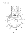
- FIG. 14 is a perspective view illustrating a simplified foundation 1a according to a second embodiment of the present invention.
- elements having similar functions to those in the first embodiment are denoted by the same reference characters, and any descriptions thereof will be omitted herein.
- the support in the shape of a roughly-spherical or roughly-oval-spherical body, such that at least its upper portion is bowl-shaped, it becomes possible to enhance the strength of the support itself.
- only holes 31a, 31b, 32a, 32b, 33a, 33b, 34a, and 34b in which to insert the drive piles may be provided without providing the guide members 3a, 3b, 3c, and 3d, as shown in FIG. 14 .
- the support is hollow and bowl-shaped at least from a part on which to attach the target construction product (including the lid 4 and the holed portion 9 in FIG. 14 ) downwardly toward any part in which to insert the drive pile (including the holes 31a, 32a, 33a, and 34a in FIG. 14 ), it is possible to provide a simplified foundation having a support with enhanced strength without using any concrete.
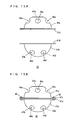
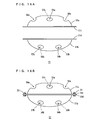
- FIGS. 15A and 15B are front views each illustrating the structure of a support 41 of a simplified foundation according to a third embodiment. Elements other than those of the structure shown in FIGS. 15A and 15B are the same as those in the second embodiment.
- the support 41 provided in the shape of a roughly-spherical body can be separated into an upper supporting portion 41a and a lower supporting portion 41b.
- the upper supporting portion 41a and the lower supporting portion 41b have their respective flange joints 41c and 41d.
- the separate upper and lower portions of the support 41 are joined at junctions 42 and 43 via bolts and nuts, for example. Note that in FIG.
- the upper supporting portion 41a and the lower supporting portion 41b are joined at two places in their peripheries, but the number of junctions is not limited.
- the upper supporting portion 41a and the lower supporting portion 41b may be joined at least at one place in their peripheries.
- the joining method is not limited to bolts and nuts, and any well-known method, such as welding or bonding, can be used. After the upper supporting portion 41a and the lower supporting portion 41b are coupled, the support 41 is placed in the soil.
- a hole 44a corresponds to a hole 44b
- a hole 45a corresponds to a hole 45b (not shown)
- a hole 46a corresponds to a hole 46b (not shown)
- a hole 47a corresponds to a hole 47b.
- the drive pile is inserted into a pair of corresponding holes.
- FIGS. 16A and 16B are front views each illustrating the structure of a support 51 of another simplified foundation according to the third embodiment. Elements other than those of the structure shown in FIGS. 16A and 16B are the same as those in the second embodiment.
- the support 51 provided in the shape of a roughly-oval-spherical body can be separated into an upper supporting portion 51a and a lower supporting portion 51b.
- the upper supporting portion 51a and the lower supporting portion 51b have their respective flange joints 51c and 51d.
- the separate upper and lower portions of the support 51 are joined at junctions 52 and 53 via bolts and nuts, for example. Note that in FIG.
- the upper supporting portion 51a and the lower supporting portion 51b are joined at two places in their peripheries, but the number of junctions is not limited.
- the upper supporting portion 51a and the lower supporting portion 51b may be joined at least at one place in their peripheries.
- the joining method is not limited to bolts and nuts, and any well-known method, such as welding or bonding, can be used. After the upper supporting portion 51a and the lower supporting portion 51b are coupled, the support 51 is placed in the soil.
- a hole 54a corresponds to a hole 54b
- a hole 55a corresponds to a hole 55b (not shown)
- a hole 56a corresponds to a hole 56b (not shown)
- a hole 57a corresponds to a hole 57b.
- the drive pile is inserted into a pair of corresponding holes.
- the support by configuring the support to be separated into the upper and lower portions, it becomes possible to transport the support in a separated state to the construction site. Accordingly, it is possible to effectively utilize the loading space for transportation compared to the case of transporting the inseparable roughly-spherical or roughly-oval-spherical support.
- the lower supporting portion is not limited to any particular shape so long as the support has a bowl-shaped upper portion.
- the guide members may be joined at their corresponding holes after the upper and lower supporting portions are joined.
- styrene foam may be embedded in at least a part of the support, thereby making it possible to prevent the simplified foundation from sinking in marshes.
- concrete may be injected into at least a part of the support depending on circumstances, thereby making it possible to further enhance the load bearing capacity.
- concrete may be injected from the holed portion 9.
- concrete may be injected before carrying-in.
- concrete may be injected into at least the lower roughly-hemispherical or roughly-oval-hemispherical portion of the support.
- any guide members it is possible to inject concrete not only at the construction site but also before carrying-in. Since only the lower half of the support is injected with concrete, the burden of carrying-in can be alleviated to some extent.
- At least one drive pile preferably more than one drive pile, may be used.
- the number of guide members to be provided may accord with the number of drive piles.
- the drive pile dose not have to be cylindrical.
- the drive pile and the guide member are not limited to such a circular-columnar shape, and they may be provided in the shape of a prismatic column or other shapes.
- the simplified foundation can be sized as below.
- the support 2 can be sized to have an outer diameter of 8 inches (203.2 mm), 10 inches (254.0mm), 12 inches (304.8 mm), or 14 inches (355.6 mm).
- FIG. 17 is a cross-sectional view showing how the dimensions of the support 51 are defined.
- the support 51 is defined for each of the upper and lower supporting portions 51a and 51b in terms of inner diameter D, internal radius R at the center, flange length L , radius r of the rounded corner, and height H excluding the flange.
- the origin of internal radius R does not have to be located on inner diameter D .
- H 0.194 D .
- R is in the range from 400 mm to 1500 mm
- the upper and lower supporting portions 51a and 51b can be provided with R incrementing by 50 mm.
- R is in the range from 1500 mm and 3000
- the upper and lower supporting portions 51a and 51b can be provided with R incrementing by 100 mm.
- the simplified foundations of the present invention can be provided in various sizes, and therefore they can be advantageously used as foundations for construction products, such as bridges, sidewalks, steps, fences, benches, tables, and play equipment.
- construction products such as bridges, sidewalks, steps, fences, benches, tables, and play equipment.
- small-sized construction products such as benches and fences
- small-sized simplified foundations may be used.
- medium-sized construction products such as bridge beams, large-sized separable simplified foundations may be used.
- the simplified foundation 1 shown in the first embodiment was actually produced, and subjected to load testing to measure its ultimate load bearing capacity.
- the simplified foundation 1 used in the testing included the spherical support 2 having a diameter of 267 mm.
- Three length classes (1 m, 2 m, and 3 m) of drive piles were used, each class consisting of four, or four pairs of, drive piles.
- the 1-m drive piles (four first drive piles 10a) were 42.7 mm in diameter.
- the 2-m drive piles (four first drive piles 10a) were 42.7 mm in diameter.
- the 3-m drive piles included four 2-m first drive piles 10a measuring 42.7 mm in diameter each paired with a 3-m second drive pile 11a measuring 34.0 mm in diameter.
- the second drive pile 11a in each pair is three meters long, the portion of the second drive pile 11a projecting from the tip of the first drive pile 10a was one meter long, and therefore the entire length of the drive pile pair was three meters long.
- the guide members 3a through 3d were 0.3 meter long. Accordingly, the portion of the drive pile that was driven and brought into the soil to effectively act as a part of the foundation had a length equivalent to the pile length minus 0.3 meter.
- the testing was conducted in private at the sandy-soiled ground within a golf course in Hyogo, Japan, in accordance with the following procedures.
- a Swedish sounding test was conducted (in compliance with JIS A1221) to confirm whether the ground in which to install the simplified foundations 1 was soft.
- a plate load test was conducted (in compliance with the Japanese Geotechnical Society standard JGS 1521-2003) after installing the simplified foundations 1 in the ground and driving the drive piles into the soil.
- the plate load test was performed on the simplified foundations 1 with the pile lengths of 1 m, 2m, and 3 m, respectively.
- Table 1 shows N-values versus depth regarding the site No. 1, and the site No. 2 near the site No. 1.
- the N-value reached 24.3 for a depth of 2.90 m.
- the N-value reached 11.4 for a depth of 2.50 m. Accordingly, strata having a depth of 2.50 m or more were not suitable for the test.
- the inclination angle of the guide members 3a through 3d was set at 40 degrees, so that the tips of the drive piles reached a depth of up to about 2 m.
- the test strata excluding those having a depth of 2.90 m (the site No.
- a load device was composed of a load plate, a separable hydraulic jack, a standpipe, and a reaction device. After placing a steel disk measuring 300 mm in diameter and 25 mm in thickness on the simplified foundation 1 as the load plate, the hydraulic jack was placed on the load plate, and the standpipe was disposed between the hydraulic jack and the reaction device such that the reaction force of the hydraulic jack was received by the reaction device.
- the reaction device used was a backhoe.
- the load plate, the hydraulic jack, the standpipe, and the reaction device were assembled together in such a manner that no eccentric load was applied.
- a measurement device was composed of a load meter and a settlement measurement device.
- the settlement measurement device was attached to a fixed girder to measure the settlement of the simplified foundation.
- the test device thus installed conducted the load test with the maximum loaded weight of 10.5 t, and the load pitch of 1.3125 t, in accordance with a multi-cycle method consisting of eight stages.
- the results of the load test are shown in Table 2.
- one simplified foundation 1 achieved the allowable long-term load bearing capacity in the range from 1.31 t to 2.62 t.
- the construction products previously produced by the present applicant generally had the load weight in the range from 0.5 t to 3.5 t.
- the above testing demonstrated that such a previous construction product could be sufficiently supported by one or more simplified foundations according to the present example, even if the ground is soft.
- the present invention provides simplified foundations that can be readily produced using as little concrete as possible, which is advantageous in the fields of architecture and civil engineering.
Landscapes
- Engineering & Computer Science (AREA)
- Structural Engineering (AREA)
- Civil Engineering (AREA)
- Life Sciences & Earth Sciences (AREA)
- General Life Sciences & Earth Sciences (AREA)
- Mining & Mineral Resources (AREA)
- Paleontology (AREA)
- General Engineering & Computer Science (AREA)
- Architecture (AREA)
- Piles And Underground Anchors (AREA)
- Foundations (AREA)
- Fencing (AREA)
Applications Claiming Priority (1)
| Application Number | Priority Date | Filing Date | Title |
|---|---|---|---|
| JP2007168103 | 2007-06-26 |
Publications (2)
| Publication Number | Publication Date |
|---|---|
| EP2009182A2 true EP2009182A2 (de) | 2008-12-31 |
| EP2009182A3 EP2009182A3 (de) | 2009-03-04 |
Family
ID=39721973
Family Applications (1)
| Application Number | Title | Priority Date | Filing Date |
|---|---|---|---|
| EP08252112A Withdrawn EP2009182A3 (de) | 2007-06-26 | 2008-06-19 | Vereinfachtes Fundament und Erdbearbeitungsverfahren damit |
Country Status (5)
| Country | Link |
|---|---|
| US (1) | US20090003938A1 (de) |
| EP (1) | EP2009182A3 (de) |
| JP (1) | JP4335958B2 (de) |
| KR (1) | KR20080114529A (de) |
| CN (1) | CN101333819A (de) |
Cited By (6)
| Publication number | Priority date | Publication date | Assignee | Title |
|---|---|---|---|---|
| WO2010000403A3 (de) * | 2008-07-01 | 2010-06-17 | Alpintechnik Ag | Stabilisator mit justiervorrichtung für bodenverankerungen |
| WO2010119432A3 (en) * | 2009-04-16 | 2011-04-21 | Agostino Bauletti | Anchoring system |
| ITMO20120265A1 (it) * | 2012-10-31 | 2014-05-01 | Guido Bardelli | Sistema di ancoraggio di oggetti in terreni |
| GB2553661A (en) * | 2016-05-25 | 2018-03-14 | Shire Consulting Ltd | An apparatus for supporting a structure |
| GB2607843B (en) * | 2021-05-28 | 2024-01-17 | Solarport Systems Ltd | A ground anchor system |
| AU2019240664B2 (en) * | 2018-10-03 | 2024-10-10 | Pandoe Pty Ltd | Support frame |
Families Citing this family (34)
| Publication number | Priority date | Publication date | Assignee | Title |
|---|---|---|---|---|
| CA2765046C (en) | 2009-06-10 | 2014-04-08 | Keystone Engineering, Inc. | Offshore support structure and associated method of installing |
| KR100952596B1 (ko) * | 2009-07-16 | 2010-04-15 | (주)일산금속 | 습지용 기초 구조물 |
| KR101043605B1 (ko) | 2009-08-04 | 2011-06-22 | 주식회사 언딘 | 해상 구조물의 설치를 위한 연약지반용 단일 지지 파일의 멀티형 서포트 커넥터 기구 |
| DE102009037175A1 (de) * | 2009-08-12 | 2011-02-17 | Stahlwerk Annahütte Max Aicher GmbH & Co. KG | Verankerungssystem |
| US8602123B2 (en) * | 2009-08-18 | 2013-12-10 | Crux Subsurface, Inc. | Spindrill |
| WO2013000022A1 (en) * | 2011-06-28 | 2013-01-03 | Despotellis Neil | Improved footing plates |
| KR101337397B1 (ko) | 2011-07-15 | 2013-12-06 | 최낙현 | 기초지지장치 |
| KR101157379B1 (ko) * | 2011-07-20 | 2012-06-20 | 장수호 | 시공 시간이 단축되는 친환경 기둥 지지대 |
| US8714881B2 (en) * | 2012-04-17 | 2014-05-06 | Richard J. Gagliano | Multiple pile foundation locking systems |
| JP2014015826A (ja) * | 2012-06-12 | 2014-01-30 | Lasco Japan Co Ltd | 基礎組立体およびそれを用いた完成構造物 |
| KR20140007738A (ko) * | 2012-07-10 | 2014-01-20 | 가부시키가이샤 라스코 재팬 | 기초 구조물 및 그것을 이용한 완성 구조물 |
| JP6084793B2 (ja) * | 2012-07-10 | 2017-02-22 | 株式会社ラスコジャパン | 基礎構造物および杭 |
| CN104685132B (zh) * | 2012-07-20 | 2017-02-22 | 伊藤组土建株式会社 | 桩基以及桩基设置方法 |
| JP5980620B2 (ja) * | 2012-08-20 | 2016-08-31 | 窪倉電設株式会社 | ソーラーパネルシステム |
| JP5896529B2 (ja) * | 2012-11-27 | 2016-03-30 | 大成建設株式会社 | 基礎構造 |
| KR101353492B1 (ko) | 2013-11-29 | 2014-01-20 | 주식회사 이토피아이앤씨 | 파일 기초 결합용 다축 조인트 |
| KR101353488B1 (ko) | 2013-11-29 | 2014-01-20 | 주식회사 이토피아이앤씨 | 다중 지지 파일 기초 |
| DE102014006581A1 (de) * | 2014-05-02 | 2015-11-05 | Beate Diehl | Vorrichtung, Verfahren und System zur erschütterungs- und setzungsfreien Gründung und Befestigung von Bauteilen im Baugrund |
| US9828739B2 (en) | 2015-11-04 | 2017-11-28 | Crux Subsurface, Inc. | In-line battered composite foundations |
| CN105421481A (zh) * | 2015-12-08 | 2016-03-23 | 山东鑫宏光电科技有限公司 | 一种扎根混凝土桩及其制备方法 |
| CN105538476A (zh) * | 2015-12-08 | 2016-05-04 | 刘丽霞 | 一种预制固定桩及其制备方法 |
| CA2963531A1 (fr) * | 2017-04-05 | 2017-08-15 | Francis Boucher | Dispositif pour soulever et stabiliser la fondation d'un batiment |
| US11078641B2 (en) * | 2017-11-06 | 2021-08-03 | Richard J. Gagliano | Foundation integral construction components and support systems |
| NL2020037B1 (en) * | 2017-12-07 | 2019-06-19 | Ihc Holland Ie Bv | A coupling system, an assembly of a vessel and a coupling system, and an assembly of a coupling system, jacket pile and foundation pile |
| CN108979288B (zh) * | 2018-07-27 | 2020-05-22 | 国网河北省电力有限公司隆尧县供电分公司 | 一种抗倒伏电杆 |
| US11085167B2 (en) * | 2018-10-02 | 2021-08-10 | Greg G. Walliman | Building foundation repair pier and permanent support |
| PL427071A1 (pl) * | 2018-10-19 | 2020-04-20 | Wójcikowski Adam | Kotwa gruntowa |
| KR102270977B1 (ko) * | 2019-12-17 | 2021-06-30 | 주식회사 비케이에너지 | 태양광발전장치의 연약지반용 프레임조립체 |
| CN111648397A (zh) * | 2020-06-30 | 2020-09-11 | 中冶华天南京工程技术有限公司 | 标牌基础及其施工方法 |
| JP7094587B1 (ja) | 2021-09-24 | 2022-07-04 | 鴎 ▲トウ▼ | 汎用支柱対応型多杭固定基礎用ベース部材、汎用支柱対応型多杭固定基礎、及び架台 |
| KR102651176B1 (ko) | 2023-04-20 | 2024-03-26 | 김영미 | 강재 말뚝 기초 및 그 시공방법 |
| KR102892326B1 (ko) * | 2023-12-29 | 2025-11-26 | 박승규 | 강재 말뚝 구조체를 이용한 파라솔형 퍼걸러 구조물 |
| KR20250141998A (ko) | 2024-03-21 | 2025-09-30 | 김영미 | 강재 말뚝 기초 및 그 시공방법 |
| KR102865332B1 (ko) * | 2025-07-18 | 2025-09-26 | 주식회사 태종금속 | 급발진 차량의 진입 차단용 볼라드 |
Citations (7)
| Publication number | Priority date | Publication date | Assignee | Title |
|---|---|---|---|---|
| US5039256A (en) | 1990-03-15 | 1991-08-13 | Richard Gagliano | Pinned foundation system |
| US5395184A (en) | 1993-01-29 | 1995-03-07 | Gagliano; Richard J. | Structure load transfer systems |
| JP2002030679A (ja) | 2000-07-19 | 2002-01-31 | Topy Green Kk | 温室用基礎及び温室 |
| US6910832B2 (en) | 2003-07-31 | 2005-06-28 | Richard J. Gagliano | Surface structures and methods thereof |
| JP2005299214A (ja) | 2004-04-12 | 2005-10-27 | Tech Taiyo Kogyo Co Ltd | 簡易基礎及び簡易基礎の集合体 |
| JP2005299215A (ja) | 2004-04-12 | 2005-10-27 | Tech Taiyo Kogyo Co Ltd | 簡易基礎及び簡易基礎の集合体 |
| US7076925B2 (en) | 2000-08-30 | 2006-07-18 | Pin Foundations, Inc. | Integrated footings |
Family Cites Families (10)
| Publication number | Priority date | Publication date | Assignee | Title |
|---|---|---|---|---|
| GB370383A (en) * | 1930-11-05 | 1932-04-05 | Aubrey Frederic Burstall | Improvements in or relating to the fabrication of metallic structures |
| GB410595A (en) * | 1933-03-23 | 1934-05-24 | Donald Stuart Kennedy | Improvements in and relating to ground anchors |
| US4161088A (en) * | 1977-11-11 | 1979-07-17 | Gugliotta Paul F | Pipe-and-ball truss array |
| CA1220925A (en) * | 1984-10-16 | 1987-04-28 | Peter H. Gammon | Ice probe and ice anchor incorporating one or more ice probes |
| IES922834A2 (en) * | 1992-11-20 | 1994-04-20 | Robin Francis Courtney Beer | Mounting arrangements |
| JP3271951B2 (ja) * | 1998-02-26 | 2002-04-08 | 環境工学株式会社 | 土木構築物用施工石、土木構築物用施工石の製造方法、土木構築物用施工石の使用方法、土木構築物用施工石ユニット及び土木構築物 |
| US6298618B1 (en) * | 1998-07-02 | 2001-10-09 | Robert Lawson | Constructional support |
| US6578333B1 (en) * | 2000-08-30 | 2003-06-17 | Richard J. Gagliano | Integrated precast footings |
| JP2004044198A (ja) * | 2002-07-11 | 2004-02-12 | Mitsubishi Heavy Ind Ltd | ジャケット式基礎 |
| US7326003B2 (en) * | 2003-07-31 | 2008-02-05 | Gagliano Richard J | Surface structures and methods thereof |
-
2008
- 2008-06-05 JP JP2008148509A patent/JP4335958B2/ja not_active Expired - Fee Related
- 2008-06-13 US US12/138,775 patent/US20090003938A1/en not_active Abandoned
- 2008-06-19 KR KR1020080057975A patent/KR20080114529A/ko not_active Ceased
- 2008-06-19 EP EP08252112A patent/EP2009182A3/de not_active Withdrawn
- 2008-06-24 CN CNA2008101318139A patent/CN101333819A/zh active Pending
Patent Citations (7)
| Publication number | Priority date | Publication date | Assignee | Title |
|---|---|---|---|---|
| US5039256A (en) | 1990-03-15 | 1991-08-13 | Richard Gagliano | Pinned foundation system |
| US5395184A (en) | 1993-01-29 | 1995-03-07 | Gagliano; Richard J. | Structure load transfer systems |
| JP2002030679A (ja) | 2000-07-19 | 2002-01-31 | Topy Green Kk | 温室用基礎及び温室 |
| US7076925B2 (en) | 2000-08-30 | 2006-07-18 | Pin Foundations, Inc. | Integrated footings |
| US6910832B2 (en) | 2003-07-31 | 2005-06-28 | Richard J. Gagliano | Surface structures and methods thereof |
| JP2005299214A (ja) | 2004-04-12 | 2005-10-27 | Tech Taiyo Kogyo Co Ltd | 簡易基礎及び簡易基礎の集合体 |
| JP2005299215A (ja) | 2004-04-12 | 2005-10-27 | Tech Taiyo Kogyo Co Ltd | 簡易基礎及び簡易基礎の集合体 |
Cited By (10)
| Publication number | Priority date | Publication date | Assignee | Title |
|---|---|---|---|---|
| WO2010000403A3 (de) * | 2008-07-01 | 2010-06-17 | Alpintechnik Ag | Stabilisator mit justiervorrichtung für bodenverankerungen |
| WO2010119432A3 (en) * | 2009-04-16 | 2011-04-21 | Agostino Bauletti | Anchoring system |
| US8561361B2 (en) | 2009-04-16 | 2013-10-22 | Agostino Bauletti | Anchoring system |
| ITMO20120265A1 (it) * | 2012-10-31 | 2014-05-01 | Guido Bardelli | Sistema di ancoraggio di oggetti in terreni |
| WO2014068604A1 (en) * | 2012-10-31 | 2014-05-08 | Bardelli Guido | Anchoring system of objects in the ground |
| US9499998B2 (en) | 2012-10-31 | 2016-11-22 | Guido Bardelli | Anchoring system of objects in the ground |
| GB2553661A (en) * | 2016-05-25 | 2018-03-14 | Shire Consulting Ltd | An apparatus for supporting a structure |
| GB2553661B (en) * | 2016-05-25 | 2021-10-06 | Shire Consulting Ltd | An apparatus for supporting a structure |
| AU2019240664B2 (en) * | 2018-10-03 | 2024-10-10 | Pandoe Pty Ltd | Support frame |
| GB2607843B (en) * | 2021-05-28 | 2024-01-17 | Solarport Systems Ltd | A ground anchor system |
Also Published As
| Publication number | Publication date |
|---|---|
| KR20080114529A (ko) | 2008-12-31 |
| JP2009030428A (ja) | 2009-02-12 |
| US20090003938A1 (en) | 2009-01-01 |
| EP2009182A3 (de) | 2009-03-04 |
| JP4335958B2 (ja) | 2009-09-30 |
| CN101333819A (zh) | 2008-12-31 |
Similar Documents
| Publication | Publication Date | Title |
|---|---|---|
| EP2009182A2 (de) | Vereinfachtes Fundament und Erdbearbeitungsverfahren damit | |
| US8584413B1 (en) | Easily connectable anchor and pillblock replacement for an embedded wooden post | |
| US5368416A (en) | Building component for a noise barrier retaining wall | |
| CN100567659C (zh) | 铁塔的基础构造 | |
| JP3899354B2 (ja) | 免震建物 | |
| US3352120A (en) | Reinforced concrete pile | |
| KR20110105617A (ko) | 구조물용 기초말뚝 | |
| JP3690437B2 (ja) | 既存建築物の耐震補強構造 | |
| CN100580193C (zh) | 铁塔的基础构造 | |
| EP3225746B1 (de) | Tragstruktur | |
| KR20050006598A (ko) | 건축물의 기초 기둥 구축용 조립식 콘크리트 거푸집 | |
| JP3899094B2 (ja) | 鋼管杭圧入による既存構造物の基礎補強工法 | |
| KR101127475B1 (ko) | 띠장 연결장치 | |
| JP2010053680A (ja) | 杭頭接合部材及びこれを用いた杭頭接合構造 | |
| JP4703233B2 (ja) | 建物基礎の補強方法及び補強構造 | |
| JP2006348526A (ja) | 複合杭基礎構造、及び構造物の杭基礎型支持方法 | |
| JPH07119147A (ja) | グラウンドアンカーの受圧板およびその設置方法 | |
| JP3270433B2 (ja) | 根入れ式擁壁 | |
| JP3680150B1 (ja) | 建造物の基礎及びその施工方法 | |
| CN211080212U (zh) | 一种路基复合地基桩帽施工机构 | |
| JP3238390U (ja) | シェルター | |
| JP4746462B2 (ja) | 地下構造物 | |
| CN222457057U (zh) | 一种土木工程用围挡 | |
| US334719A (en) | Fence-post | |
| JP3682504B2 (ja) | 建築物の基礎とその施工方法 |
Legal Events
| Date | Code | Title | Description |
|---|---|---|---|
| PUAI | Public reference made under article 153(3) epc to a published international application that has entered the european phase |
Free format text: ORIGINAL CODE: 0009012 |
|
| AK | Designated contracting states |
Kind code of ref document: A2 Designated state(s): AT BE BG CH CY CZ DE DK EE ES FI FR GB GR HR HU IE IS IT LI LT LU LV MC MT NL NO PL PT RO SE SI SK TR |
|
| AX | Request for extension of the european patent |
Extension state: AL BA MK RS |
|
| PUAL | Search report despatched |
Free format text: ORIGINAL CODE: 0009013 |
|
| AK | Designated contracting states |
Kind code of ref document: A3 Designated state(s): AT BE BG CH CY CZ DE DK EE ES FI FR GB GR HR HU IE IS IT LI LT LU LV MC MT NL NO PL PT RO SE SI SK TR |
|
| AX | Request for extension of the european patent |
Extension state: AL BA MK RS |
|
| RIN1 | Information on inventor provided before grant (corrected) |
Inventor name: HIROSHI NISHIMORI |
|
| AKX | Designation fees paid | ||
| REG | Reference to a national code |
Ref country code: DE Ref legal event code: 8566 |
|
| STAA | Information on the status of an ep patent application or granted ep patent |
Free format text: STATUS: THE APPLICATION IS DEEMED TO BE WITHDRAWN |
|
| 18D | Application deemed to be withdrawn |
Effective date: 20090907 |