EP2009219A2 - Store doté d'un dispositif serrage et élément de isolant multicouche doté d'un tel store - Google Patents
Store doté d'un dispositif serrage et élément de isolant multicouche doté d'un tel store Download PDFInfo
- Publication number
- EP2009219A2 EP2009219A2 EP08159304A EP08159304A EP2009219A2 EP 2009219 A2 EP2009219 A2 EP 2009219A2 EP 08159304 A EP08159304 A EP 08159304A EP 08159304 A EP08159304 A EP 08159304A EP 2009219 A2 EP2009219 A2 EP 2009219A2
- Authority
- EP
- European Patent Office
- Prior art keywords
- roller
- shaft
- take
- blind
- cloth
- Prior art date
- Legal status (The legal status is an assumption and is not a legal conclusion. Google has not performed a legal analysis and makes no representation as to the accuracy of the status listed.)
- Granted
Links
- 239000011521 glass Substances 0.000 title claims abstract description 42
- 239000004744 fabric Substances 0.000 claims abstract description 69
- 239000011888 foil Substances 0.000 claims abstract description 5
- 239000002184 metal Substances 0.000 claims abstract description 4
- 238000004804 winding Methods 0.000 claims description 37
- 230000005291 magnetic effect Effects 0.000 claims description 8
- 230000005415 magnetization Effects 0.000 claims description 4
- 238000003780 insertion Methods 0.000 claims description 2
- 230000037431 insertion Effects 0.000 claims description 2
- 239000000463 material Substances 0.000 abstract description 3
- 241001131688 Coracias garrulus Species 0.000 abstract 7
- 238000005096 rolling process Methods 0.000 abstract 2
- 239000005357 flat glass Substances 0.000 description 16
- 238000000034 method Methods 0.000 description 4
- 238000004519 manufacturing process Methods 0.000 description 3
- 239000007787 solid Substances 0.000 description 3
- 238000011161 development Methods 0.000 description 2
- 230000018109 developmental process Effects 0.000 description 2
- 230000011664 signaling Effects 0.000 description 2
- 125000006850 spacer group Chemical group 0.000 description 2
- 238000010521 absorption reaction Methods 0.000 description 1
- 238000004378 air conditioning Methods 0.000 description 1
- 238000005452 bending Methods 0.000 description 1
- 230000005540 biological transmission Effects 0.000 description 1
- 238000006073 displacement reaction Methods 0.000 description 1
- 230000000694 effects Effects 0.000 description 1
- 230000008030 elimination Effects 0.000 description 1
- 238000003379 elimination reaction Methods 0.000 description 1
- 230000005294 ferromagnetic effect Effects 0.000 description 1
- 239000003302 ferromagnetic material Substances 0.000 description 1
- 230000004313 glare Effects 0.000 description 1
- 230000001771 impaired effect Effects 0.000 description 1
- 238000009434 installation Methods 0.000 description 1
- 230000010354 integration Effects 0.000 description 1
- 239000011185 multilayer composite material Substances 0.000 description 1
- 230000005855 radiation Effects 0.000 description 1
- 230000001846 repelling effect Effects 0.000 description 1
- 239000004753 textile Substances 0.000 description 1
Images

Classifications
-
- E—FIXED CONSTRUCTIONS
- E06—DOORS, WINDOWS, SHUTTERS, OR ROLLER BLINDS IN GENERAL; LADDERS
- E06B—FIXED OR MOVABLE CLOSURES FOR OPENINGS IN BUILDINGS, VEHICLES, FENCES OR LIKE ENCLOSURES IN GENERAL, e.g. DOORS, WINDOWS, BLINDS, GATES
- E06B9/00—Screening or protective devices for wall or similar openings, with or without operating or securing mechanisms; Closures of similar construction
- E06B9/24—Screens or other constructions affording protection against light, especially against sunshine; Similar screens for privacy or appearance; Slat blinds
- E06B9/40—Roller blinds
- E06B9/42—Parts or details of roller blinds, e.g. suspension devices, blind boxes
-
- E—FIXED CONSTRUCTIONS
- E06—DOORS, WINDOWS, SHUTTERS, OR ROLLER BLINDS IN GENERAL; LADDERS
- E06B—FIXED OR MOVABLE CLOSURES FOR OPENINGS IN BUILDINGS, VEHICLES, FENCES OR LIKE ENCLOSURES IN GENERAL, e.g. DOORS, WINDOWS, BLINDS, GATES
- E06B9/00—Screening or protective devices for wall or similar openings, with or without operating or securing mechanisms; Closures of similar construction
- E06B9/56—Operating, guiding or securing devices or arrangements for roll-type closures; Spring drums; Tape drums; Counterweighting arrangements therefor
- E06B9/62—Counterweighting arrangements
-
- E—FIXED CONSTRUCTIONS
- E06—DOORS, WINDOWS, SHUTTERS, OR ROLLER BLINDS IN GENERAL; LADDERS
- E06B—FIXED OR MOVABLE CLOSURES FOR OPENINGS IN BUILDINGS, VEHICLES, FENCES OR LIKE ENCLOSURES IN GENERAL, e.g. DOORS, WINDOWS, BLINDS, GATES
- E06B9/00—Screening or protective devices for wall or similar openings, with or without operating or securing mechanisms; Closures of similar construction
- E06B9/24—Screens or other constructions affording protection against light, especially against sunshine; Similar screens for privacy or appearance; Slat blinds
- E06B9/26—Lamellar or like blinds, e.g. venetian blinds
- E06B9/264—Combinations of lamellar blinds with roller shutters, screen windows, windows, or double panes; Lamellar blinds with special devices
Definitions
- the invention relates to a roller blind for protection against sunlight, which has a tensioning device.
- shading systems are used, for example, to improve the indoor climate, the energy savings by reducing the use of air conditioning units or the elimination of glare on computer workstations.
- the invention also relates to a multi-pane insulating glass element which is equipped with such a roller blind.
- the US 262,398 shows a roller blind, the scarf is permanently stretched with a pull rope.
- the traction cable is guided over a spring-loaded roller and is wound onto a cone-shaped winding roller.
- the DE 196 10 268 C2 shows a roller blind device for an insulating glass element, in which the blind cloth is permanently stretched using a pull rope.
- the pull rope is loaded by a spring and is deflected via rollers in the free end region of the blind cloth and finally guided to a cone-shaped portion of the take-up shaft.
- Another disadvantage of this solution is that on the take-up shaft an area for winding the pull rope is provided, which is problematic due to the very limited space within an insulating glass element.
- the motor for driving the take-up shaft is designed to be resilient in order to both wind the blind sheet and to be able to overcome the friction when unwinding the pull rope.
- the take-up shaft is designed to be resilient in order to accommodate both the force for tensioning the blind cloth and the resulting counterforce. This leads to increased space requirements for the roller blind, which precludes integration in a double glass pane.
- the DE 37 40 018 A1 relates to a shading device for translucent wall or ceiling areas.
- This shading device has a winding roller for a shading track, which can be pulled with a tension element over the shaded area.
- a tension element a cable is provided, which enters a pulley, the loose roller is movable under deflection of a spring against a fixed role.
- the EP 0 276 045 B1 relates to a roller shutter with a horizontal winding roll.
- the winding roll is driven by a motor.
- the weight of the shutter is balanced with a counterweight which hangs on a loose roller over which a pull rope connected to the winding roll is guided.
- Another karseil for tensioning the shutter is guided over a loose role, which is stretched by a spring.
- the DE 32 45 009 A1 shows a roller shutter with a rollable on a shaft curtain.
- a tension member is attached to the crosshead of the curtain, which is fixed at its other end stationary.
- the tension member is preferably guided over a loose pair of rollers, which is tensioned with a tension spring.
- the EP 0 483 528 A1 shows an insulating glass arrangement with a metal foil as a blind cloth.
- the US 2003/0089462 A1 shows a method for manufacturing a magnet system for blinds.
- the magnet system is used to drive a shutter located within a multi-pane window from outside the multi-pane window.
- the DE 102 32 536 A1 shows a roller blind device with a driven cloth shaft and a windable cloth, on the free edge of a pull rod is arranged.
- a tie rod acts in the withdrawal direction of the cloth, a force.
- This force is achieved in that coaxially and in extension of the cloth shaft, a cable reel is rotatably connected to the roller tube and the free end of a rope wound thereon is connected via at least one cable deflection with the tension rod.
- there is at least one spring arrangement in the course of the cable for adapting the length of the rope to the varying winding state of the fabric shaft and cable reel.
- each rope is first steered over a fixed roller in the end of the blinds and finally ends at a tension spring in the pull rod of the blind cloth.
- the springs must be made strong enough to ensure sufficient traction over the required travel can. This is a high torque of Cloth shaft required to simultaneously wind the towel and the spring-loaded rope or unwind. The spring forces act unabated on the fabric shaft, as they are only passed over a fixed role.
- two tension springs are used, which are not arranged in the pull rod, but in the context of the roller blind device.
- the tension springs are firmly connected to the frame and each span a deflection coil, over which the rope is steered, so that the rope is tensioned.
- a disadvantage of this solution is that a correspondingly high torque must act on the cloth shaft in order to be able to simultaneously wind up or unwind the spring-tensioned rope and the cloth. Due to the solution according to the arrangement of the cable reel on the fabric shaft, it is essential to arrange the spring assembly with the deflection coils in the region of the blind cloth, in particular in the side region of the blind cloth. However, this area is to be kept free in many applications, for example in insulating glass windows.
- the from the DE 102 32 536 A1 known solutions has in common that the fabric shaft is designed to be resilient in order to absorb both the force for tensioning the blind cloth and the resulting counterforce.
- the object of the invention is based on the DE 102 32 536 A1 It is to provide a roller blind with a tensioning device for tensioning the blind cloth, in which both the applied mechanical power for winding and unwinding of the blind cloth and the mechanical loading of the blind components are reduced and in which the clamping device can be arranged such that it covers the glass surface not or only minimally covered.
- a subtask is also to include other components of the roller blind Minimizing their space requirements, whereby the suitability of the blind for space-limited applications, such as increased within a multi-pane insulating glass element.
- the shade according to the invention serves to cover a glass surface, for example a window or a glass door.
- the roller blind initially has a roll-up scarf, with which the glass surface can be optionally covered.
- the blind cloth can be wound onto a drivable winding shaft and also unwound from this. If a glass surface, which is covered by the blind sheet, be released from the blind cloth, the blind sheet is wound by the take-up shaft in a winding.
- the roller blind according to the invention has a tensioning device for tensioning the blind cloth over the glass surface. The tensioning device ensures that the scarf, regardless of the extent to which it covers the glass surface, is permanently tensioned and thus even.
- the tensioning device comprises a pull rope for acting on the blind cloth with a pulling force directed counter to the winding direction.
- the tensile force is absorbed by a constant length of the traction cable, that is, a constant length of the traction cable is subjected to the tensile force. This is equivalent to the fact that the effective length of the traction cable is not changed, as would be the case for example when unwinding or winding the traction cable on a take-up reel.
- the inclusion of the tensile force on a constant length of the traction cable is given, for example, when both ends of the traction cable are fixed to a base body of the blindststsverver selectivelich opposite the glass surface.
- the absorption of the tensile force to a constant length of the traction cable is also given, for example, when one end of the pull cable is fixed to the base body of the blindsunsistant to the glass surface, while the other end is fixed to the blind cloth.
- the inclusion of the tensile force on a constant length of the pull rope is given, for example, even if one end of the pull rope is fixed on the main body of the blindststsunver selectedlich opposite the glass surface, while the other end is fixed to a roll holder a loose role.
- the traction cable is guided at least over a loose roller, which is tensioned by a spring.
- the roller blind according to the invention has the advantage that the pull rope is not wound and tensioned via the drivable take-up shaft or another means.
- On the take-up shaft acts only the torque for winding the blind cloth, but not the counterforce for tensioning the blind cloth. Frictional forces, such as occur in a take-up roll for the traction cable according to the prior art, are avoided by the inventive solution. Consequently, the take-up shaft and its drive can be made correspondingly weaker and smaller, which is particularly advantageous for integrated roller blinds in multi-pane insulating glass elements.
- the function of the spring and the loose roller is not tied to the take-up shaft, so that the spring and the loose roller can be arranged independently of the take-up shaft.
- the traction cable can be deflected by means of other rollers such that the spring and the loose roller can be arranged at a suitable location for each application.
- the loose roller causes the travel is doubled compared to the distance traveled by the blind cloth path. This ratio can be increased by using several loose rollers. It lies in the skill and knowledge of the professional To adjust roller guide and the design of the spring according to the respective roller blind application.
- the loose roller is designed as a pulley with at least two rollers.
- the pulley can also be designed as a power pulley or as a differential pulley, whereby very large force-displacement can be achieved.
- the roller blind is enclosed in a frame which enables the insertion of the roller blind into a multi-pane insulating glass element. Since the roller blind invention allows a space-saving and flat design, it is particularly suitable for use in multi-pane insulating glass elements.
- the roller blind can be arranged between two panes of a multi-pane insulating glass element, which have a standard spacing from each other. Consequently, the shade according to the invention can be used for example in ordinary insulating glass window. The advantages of such an integrated solution are well known.
- the loose roll is preferably arranged together with the spring and the take-up shaft in a covered area within the frame.
- the traction cable must be deflected via at least one fixed roller in the direction of the take-up shaft.
- the frame is preferably formed of mated profiled bars, which are initially held together by the forces acting from the spring on the take-up shaft connected to the frame and on the fixed rollers connected to the frame. As soon as the frame has been inserted into a holder frame of the multi-pane insulating glass element, the frame is sufficiently fixed in order to be able to put the roller blind into operation.
- This embodiment has the advantage that connecting elements and corresponding manufacturing steps can be saved.
- the roller cloth is preferably made of a plastic, a multilayer composite material or a metal foil. Films require smaller forces to wind up and lead to a smaller diameter in the wound state than is the case for example with textiles.
- the roller cloth has in its winding end of the shaft facing away from the free end portion at least one deflection roller over which the pull cable is guided.
- the blind cloth can be selectively applied with a directed against the winding tension, whereby the blind cloth can be optimally tensioned.
- the traction cable is fastened with one of its two ends to the roller cloth in its free end region remote from the take-up shaft.
- the roller cloth in its the take-up shaft facing away from the free end region on two pulleys over which the pull rope is guided, wherein the pulleys are each arranged in the edge region of the blind cloth.
- the tensile force acts evenly distributed on the free corners of the blind cloth.
- the roller cloth In its free end region facing away from the winding shaft, the roller cloth preferably has a end rail, which is guided by lateral guide devices and on which the two deflection rollers are mounted.
- the end rail allows a fixation of the free edge of the blind cloth, whereby unevenness in the blind cloth can be avoided.
- the end rail allows a secure attachment of the pulleys.
- the lateral guide device for the end rail allows a defined movement of the blind cloth during the unwinding and winding process.
- the lateral guide devices can each be formed by a U-shaped rail, in each of which an outer guide pin of the end rail is guided.
- this further comprises a support element, which is arranged opposite a central axial portion of the take-up shaft in the winding direction.
- the central axial portion of the take-up shaft is magnetized, for example, by the fact that there is a permanent magnet is arranged.
- the support element is magnetic, such as ferromagnetic, executed. Consequently, there is a magnetic attraction of the support member on the take-up shaft, which acts in the winding direction. This attraction compensates for part of the pulling force of the blind cloth on the take-up shaft. Consequently, it is avoided that the Winding shaft bends due to the force acting on the take-up shaft by the roller cloth force.
- the take-up shaft can be made correspondingly weaker, for example, by having a smaller diameter.
- the central axial region of the take-up shaft can be made magnetic, for example by the fact that this or the entire take-up shaft consists of a ferromagnetic material.
- the support element is then to perform magnetically, for example in the form of a permanent magnetized permanent magnet or in the form of a temporarily magnetized electromagnet.
- Another alternative is to perform magnetized both the central axial portion of the take-up shaft and the support element, for example as a permanent magnet.
- the magnetizations are to be aligned such that the force caused by the magnetic force acts on the take-up shaft in the winding direction.
- the support member may be disposed on the take-up shaft side of the take-up shaft, with like poles facing the magnetization, thereby causing a repelling force on the take-up shaft.
- the support member may be disposed on the opposite side of the Aufwickelraum Aufwickelwelle, with different poles facing the magnetization, whereby an attractive force acts on the take-up shaft in the winding direction.
- the support element enables non-contact and almost wear-free support of the take-up shaft.
- the drivable winding shaft is preferably driven by an electric motor via a gearbox or directly.
- the roller blind further preferably comprises a first and a second limit switch, by means of which the positions of a unwound and a rolled-up roller cloth are defined.
- a first and a second limit switch In the take-up roller facing away from the free end portion of the blind cloth this has a stop which abuts against the first limit switch when the blind cloth is completely unwound, d. h. when the glass surface is completely covered.
- the stop is struck against the second limit switch when the blind cloth is fully wound, d. h., When the glass surface is completely freed from the blind cloth.
- the stop may be formed for example by the end rail.
- the roller blind according to the invention preferably further comprises an electronic control with which the electric motor can be controlled.
- the controller is electrically connected to the first and second limit switches. If the stop strikes the first limit switch during unwinding of the blind cloth, the controller first causes a stop of the rotating electric motor. Immediately thereafter, the electric motor is operated for a short time counter to the previously existing direction of rotation. As a result, a caster of the electric motor is counteracted, so as to obtain the tension of the roller cloth. If the stopper strikes the second limit switch when the blind cloth is being wound, the controller causes the electric motor to stop.
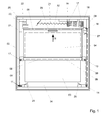
- Fig. 1 shows a preferred embodiment of the blinds according to the invention, which is used in a multi-pane insulating glass window.
- the roller blind initially has a rectangular frame 01, which is inserted precisely into a spacer frame 02 of the multi-pane insulating glass window.
- the roller blind is between a first window glass 03 and a second window glass (in Fig. 3 shown) of the multi-pane insulating glass window.
- the first window glass 03 can optionally be covered with a roll film 04 of the roller blind.
- the roll film 04 allows shading to reduce solar radiation of up to 90% or more.
- the roll film 04 can be wound onto a winding shaft 06 and unwound from this.
- the roll film 04 When the first window glass 03 is completely covered by the roll film 04, the roll film 04 is almost completely unwound from the take-up shaft 06. If the first window glass 03 is not covered by the roll film 04, ie if the first window glass 03 is completely freed from the roll film 04, the roll film 04 is wound almost completely onto the take-up shaft 06. In the state shown, the roll film 04 is approximately half unwound from the take-up shaft 06, so that the first window glass 03 is about half covered by the roll film 04.
- the roll film 04 has in its the take-up shaft 06 remote from the free end region on a end rail 08.
- the end rail 08 is fixedly connected to the free edge of the roll film 04 and is the take-up shaft 06 parallel opposite. The roller film 04 is just clamped between the end rail 08 and the take-up shaft 06.
- the roll film 04 is stretched by means of a pull cable 09.
- the pull cable 09 is connected at a first end 11 fixed to the frame 01 of the roller blind.
- the pull cable 09 is guided starting from the first end 11 via a first deflection roller 12 and a second deflection roller 13.
- the pulleys 12, 13 are attached to the end rail 08 of the roll film 04.
- the first guide roller 12 is located at a first end of the end rail 08 and the second guide roller 13 is located at a second end of the end rail 08.
- the first fixed roller 14 is located in the area of the roller blind opposite the take-up shaft 06.
- the pull cable 09 is deflected over the first fixed roller 14 in the direction of the take-up shaft 06.
- the pull cable 09 is deflected again via a second fixed roller 16 in the direction of a pulley 17.
- the pulley 17 comprises a fixed roller group 18 and a loose roller group 19.
- the loose roller group 19 is guided on the frame 01 laterally, substantially parallel to the take-up shaft 06.
- the pull cable 09 is repeatedly deflected over the rollers of the loose roller group 19 and the rollers of the fixed roller group 18 until it finally ends at the loose roller group 19, where it is fixed.
- the tension spring 21 is fastened with one of its ends to the loose roller group 19 and with its other end to the frame 01. In this way, the entire pulley 17 and the tension spring 21 are arranged parallel to the take-up shaft 06, on the side opposite the Rolloauszugs Symposium.
- the loose roller group 19 is located at a maximum distance from the fixed roller group 18.
- the tension spring has shortened significantly in this state, however, it still causes an albeit reduced spring force on the loose roller group 19, thereby further sufficient pulling force on the roll film 04 is guaranteed.
- the path of the end rail 08 of the roll film 04 from fully wound state to fully unwound state of the roll film 04 is a multiple of the way, which the loose roller group 19 while covers, since this way is cut over the pulley 17 several times. This makes it possible to use a tension spring whose travel is only a fraction of that path length over which the roller film 04 is pulled.
- the Tension spring 21 are not arranged parallel to the path of the roll film 04, but can be arranged in a suitable area, which has a shorter length.
- the area above the take-up shaft 06 since this does not cover the window glass 03 is suitable.
- the tension spring 21 can also be arranged in another suitable area of the roller blind for the respective application.
- the length of the pull cable 09, on which the tensile force acts, does not change during operation of the roller blind, that is, the active length of the pull cable 09 is constant, regardless of how far the roll film 04 is wound. It comes at most to minor changes in length of the traction cable due to the applied tensile force or due to thermal influences or as a result of material fatigue.
- the take-up shaft 06 is driven by an electric motor 22 via a gear 23.
- a torque is transmitted to the take-up shaft 06 via the gear 23, which torque is large enough to overcome the tensile force caused by the tension spring 21 on the roller film 04. It is not necessary to apply a torque which simultaneously allows winding or unwinding of the pull cable 09.
- the gear 23 drives the take-up shaft 06 via a belt drive (not shown).
- the roller blind also has a left lower limit switch 24 and a lower right limit switch 26 and an upper limit switch 27. If the roll film 04 unwound from the take-up shaft 06, the end rail 08 abuts against the two lower limit switches 24, 26 as soon as the roll film 04 completely covers the first window glass 03. If the roll film 04 wound on the take-up shaft 06, so the end rail 08 suggests upper limit switch 27 as soon as the roll film 04 has the window glass 03 substantially completely released.
- the limit switches 24, 26, 27 are connected to an electronic control 28 for controlling the electric motor. By means of the limit switches 24, 26, 27, the electronic control 28 can be signaled when the roll film 04 has reached an end position.
- This signaling is independent of whether the roll film 04, for example due to heat effects, has expanded or shortened. Likewise, this signaling is independent of whether the pull cable 09 has expanded due to thermal influences or material fatigue.
- the limit switches 24, 26, 27 are designed as mechanical limit switches, whereby a cost-effective production is possible.
- the limit switches 24, 26, 27 can also be designed as electronic switches, for example as proximity switches.
- the lower left limit switch 24 and the right lower limit switch 26 can be made redundant to each other, so that one of the two lower limit switches 24, 26 may fail without the function of the roller blind is impaired.
- the roller blind also has a permanent magnet 29, which is arranged on one of the winding direction 31 facing side of the take-up shaft 06 and the take-up shaft 06 faces.
- the permanent magnet 29 is in particular opposite a central axial portion 32 of the take-up shaft 06, which has a permanent magnet insert (not shown).
- the permanent magnet 29 and the permanent magnet insert in the central axial portion 32 of the take-up shaft 06 are aligned such that they repel due to the force caused by the magnetic force. Consequently, the fixed relative to the frame 01 of the roller blind permanent magnet 29 acts as a support for the take-up shaft 06.
- the tensile force caused by the tension spring 21 on the roll film 04 acts against the winding direction 31 on the take-up shaft 06 and causes in particular in the central axial portion 32 a bending of the Winding shaft 06 against the winding direction 31. This deflection is largely avoided by the permanent magnet 29 and the permanent magnet insert. Therefore, the take-up shaft 06 can be made less resilient, especially with a smaller diameter.
- the reduced diameter of the take-up shaft 06 results in that the entire blind can be made with a small thickness, whereby it is suitable for multi-pane insulating glass window in which the distance between the windows is not increased compared to standard dimensions.
- the diameter of the take-up shaft 06 including the completely wound roll film 04 is only 14 mm in the illustrated embodiment.
- Fig. 2 shows a sectional view through the roller blind according to the invention.
- the frame 01, the take-up shaft 06 and the roll film 04 are shown.
- the roll film 04 is wound to a part on the take-up shaft 06.
- the permanent magnet 29 is shown, which the take-up shaft 06 supported.
- the end rail 08 is also shown in the free end region of the roll film 04.
- the pull cable 09 is guided longitudinally through the inner region of the end rail 08.
- Fig. 3 shows an enlarged detail of the structure of the multi-pane insulating glass window with the built-frame 01 of the blind.
- the frame 01 comprises four profile bars 33 and two screens 34, which form the six sides of the frame 01.
- Fig. 3 shows one of the profile bars 33 and the two panels 34 belonging to the panels 34 and inserted into the profile bar 33 tabs 36.
- Fig. 3 furthermore, the first window glass 03 and the second window glass 37 as well as an insulating glass seal 38 located between the two window glasses 03, 37 are shown.
Landscapes
- Engineering & Computer Science (AREA)
- Structural Engineering (AREA)
- Architecture (AREA)
- Civil Engineering (AREA)
- Operating, Guiding And Securing Of Roll- Type Closing Members (AREA)
- Blinds (AREA)
Applications Claiming Priority (1)
| Application Number | Priority Date | Filing Date | Title |
|---|---|---|---|
| DE200710030357 DE102007030357B4 (de) | 2007-06-29 | 2007-06-29 | Rollo mit Spannvorrichtung sowie Mehrscheiben-Isolierglaselement mit einem solchen Rollo |
Publications (3)
| Publication Number | Publication Date |
|---|---|
| EP2009219A2 true EP2009219A2 (fr) | 2008-12-31 |
| EP2009219A3 EP2009219A3 (fr) | 2012-08-22 |
| EP2009219B1 EP2009219B1 (fr) | 2013-11-06 |
Family
ID=39831978
Family Applications (1)
| Application Number | Title | Priority Date | Filing Date |
|---|---|---|---|
| EP20080159304 Not-in-force EP2009219B1 (fr) | 2007-06-29 | 2008-06-28 | Store à rouleau doté d'un dispositif de tendeur et multiple vitrage isolant doté d'un tel store |
Country Status (2)
| Country | Link |
|---|---|
| EP (1) | EP2009219B1 (fr) |
| DE (1) | DE102007030357B4 (fr) |
Cited By (3)
| Publication number | Priority date | Publication date | Assignee | Title |
|---|---|---|---|---|
| CN103032018A (zh) * | 2012-12-19 | 2013-04-10 | 绍兴文理学院 | 一种光致智能变色窗及其使用方法 |
| CN106979478A (zh) * | 2017-04-27 | 2017-07-25 | 浙江海洋大学东海科学技术学院 | 港口电气节能照明设备 |
| CN108661532A (zh) * | 2018-07-25 | 2018-10-16 | 江苏赛迪乐节能科技有限公司 | 中空玻璃内置百叶窗的牵引绳涨紧装置 |
Families Citing this family (1)
| Publication number | Priority date | Publication date | Assignee | Title |
|---|---|---|---|---|
| DE202008015917U1 (de) * | 2008-12-02 | 2010-04-22 | Inalfa Roof Systems Group B.V. | Scheibenanordnung |
Citations (8)
| Publication number | Priority date | Publication date | Assignee | Title |
|---|---|---|---|---|
| US262398A (en) | 1882-08-08 | gxraed | ||
| DE3245009A1 (de) | 1982-12-06 | 1984-06-14 | Adolf Seuster GmbH, 5880 Lüdenscheid | Rolltor |
| DE3740018A1 (de) | 1987-11-26 | 1989-06-08 | Elram Wintergartentechnik Gmbh | Vorrichtung zur betaetigung einer beschattungseinrichtung |
| EP0276045B1 (fr) | 1987-01-17 | 1992-03-25 | Clark Door Limited | Portes enroulables |
| EP0483528A1 (fr) | 1990-10-01 | 1992-05-06 | INN-GLASBAU GmbH | Système de vitres isolantes |
| DE19610268C2 (de) | 1996-03-15 | 2001-05-23 | Consafis Glas Conzelmann Gmbh | Rolloeinrichtung für ein Isolierglaselement |
| US20030089462A1 (en) | 2000-06-22 | 2003-05-15 | Zhongming Wang | Method of manufacturing the magnetic operation system used in a venetian blind or the like placed inside an insulating glass frame |
| DE10232536A1 (de) | 2002-07-18 | 2004-02-12 | Philipp Tussinger | Rollovorrichtung |
Family Cites Families (1)
| Publication number | Priority date | Publication date | Assignee | Title |
|---|---|---|---|---|
| FR2594173A1 (fr) * | 1986-02-07 | 1987-08-14 | Morillon Alain | Systeme motorise permettant le deroulement d'ecrans souples avec maintien en tension multidirectionnelle |
-
2007
- 2007-06-29 DE DE200710030357 patent/DE102007030357B4/de not_active Expired - Fee Related
-
2008
- 2008-06-28 EP EP20080159304 patent/EP2009219B1/fr not_active Not-in-force
Patent Citations (8)
| Publication number | Priority date | Publication date | Assignee | Title |
|---|---|---|---|---|
| US262398A (en) | 1882-08-08 | gxraed | ||
| DE3245009A1 (de) | 1982-12-06 | 1984-06-14 | Adolf Seuster GmbH, 5880 Lüdenscheid | Rolltor |
| EP0276045B1 (fr) | 1987-01-17 | 1992-03-25 | Clark Door Limited | Portes enroulables |
| DE3740018A1 (de) | 1987-11-26 | 1989-06-08 | Elram Wintergartentechnik Gmbh | Vorrichtung zur betaetigung einer beschattungseinrichtung |
| EP0483528A1 (fr) | 1990-10-01 | 1992-05-06 | INN-GLASBAU GmbH | Système de vitres isolantes |
| DE19610268C2 (de) | 1996-03-15 | 2001-05-23 | Consafis Glas Conzelmann Gmbh | Rolloeinrichtung für ein Isolierglaselement |
| US20030089462A1 (en) | 2000-06-22 | 2003-05-15 | Zhongming Wang | Method of manufacturing the magnetic operation system used in a venetian blind or the like placed inside an insulating glass frame |
| DE10232536A1 (de) | 2002-07-18 | 2004-02-12 | Philipp Tussinger | Rollovorrichtung |
Cited By (4)
| Publication number | Priority date | Publication date | Assignee | Title |
|---|---|---|---|---|
| CN103032018A (zh) * | 2012-12-19 | 2013-04-10 | 绍兴文理学院 | 一种光致智能变色窗及其使用方法 |
| CN106979478A (zh) * | 2017-04-27 | 2017-07-25 | 浙江海洋大学东海科学技术学院 | 港口电气节能照明设备 |
| CN106979478B (zh) * | 2017-04-27 | 2019-05-24 | 浙江海洋大学东海科学技术学院 | 港口电气节能照明设备 |
| CN108661532A (zh) * | 2018-07-25 | 2018-10-16 | 江苏赛迪乐节能科技有限公司 | 中空玻璃内置百叶窗的牵引绳涨紧装置 |
Also Published As
| Publication number | Publication date |
|---|---|
| EP2009219A3 (fr) | 2012-08-22 |
| DE102007030357A1 (de) | 2009-01-02 |
| EP2009219B1 (fr) | 2013-11-06 |
| DE102007030357B4 (de) | 2009-09-03 |
Similar Documents
| Publication | Publication Date | Title |
|---|---|---|
| EP1525368B1 (fr) | Systeme de store | |
| EP2060421B1 (fr) | Agencement de store doté d'un entraînement à friction réduite | |
| WO2001053647A1 (fr) | Plaque de verre isolante comportant un systeme de store integre | |
| DE19610268C2 (de) | Rolloeinrichtung für ein Isolierglaselement | |
| EP2009219B1 (fr) | Store à rouleau doté d'un dispositif de tendeur et multiple vitrage isolant doté d'un tel store | |
| DE3245009A1 (de) | Rolltor | |
| EP1626152A1 (fr) | Protection solaire pour un toit vitré | |
| EP1191183B1 (fr) | Système de vitres isolantes avec store à enrouleur en forme de feuille | |
| DE102008008941B4 (de) | Sonnenschutzanlage mit einem wickelbaren Behang | |
| DE102009045746A1 (de) | Rolloanordnung mit wengistens einer Wickelwelle und einem Vorhangelement sowie Glaseinheit und Verfahren zum Auf- und/oder Abwickeln eines Vorhangelements von einer Wickelwelle | |
| DE3743366A1 (de) | Waermerollo mit seitlicher magnetbandfuehrung | |
| DE69727104T2 (de) | Auf- und Abrollvorrichtung für ein Gewebe | |
| DE102022129357A1 (de) | Isolierglasanordnung | |
| EP1840320B1 (fr) | Store enrouleur à câble | |
| DE20210855U1 (de) | Rollovorrichtung | |
| EP1736628A1 (fr) | Dispositif de guidage pour une porte coulissante | |
| EP0529591A1 (fr) | Dispositif de store, de préference pour lunettes arrières de véhicules | |
| EP4365403A2 (fr) | Ensemble de vitrage isolant avec protection solaire ou rideau d'obscurcissement intégré | |
| DE102022129359A1 (de) | Isolierglasanordnung | |
| DE102022129360A1 (de) | Isolierglasanordnung | |
| DE102005056608A1 (de) | Rollovorrichtung, insbesondere für ein Schiebedachsystem | |
| DE202024100283U1 (de) | Isolierglasanordnung | |
| EP4253711A1 (fr) | Dispositif d'enroulement destiné à être utilisé sur un dispositif de protection solaire | |
| DE10063454B4 (de) | Vorrichtung zum Verschließen und/oder Beschatten eines Öffnungsquerschnitts bzw. einer Fläche | |
| WO2004029396A1 (fr) | Porte a coulissement rapide |
Legal Events
| Date | Code | Title | Description |
|---|---|---|---|
| PUAI | Public reference made under article 153(3) epc to a published international application that has entered the european phase |
Free format text: ORIGINAL CODE: 0009012 |
|
| AK | Designated contracting states |
Kind code of ref document: A2 Designated state(s): AT BE BG CH CY CZ DE DK EE ES FI FR GB GR HR HU IE IS IT LI LT LU LV MC MT NL NO PL PT RO SE SI SK TR |
|
| AX | Request for extension of the european patent |
Extension state: AL BA MK RS |
|
| RAP1 | Party data changed (applicant data changed or rights of an application transferred) |
Owner name: PARTNERFONDS >KAPITAL FUER DEN MITTELSTAND < |
|
| PUAL | Search report despatched |
Free format text: ORIGINAL CODE: 0009013 |
|
| AK | Designated contracting states |
Kind code of ref document: A3 Designated state(s): AT BE BG CH CY CZ DE DK EE ES FI FR GB GR HR HU IE IS IT LI LT LU LV MC MT NL NO PL PT RO SE SI SK TR |
|
| AX | Request for extension of the european patent |
Extension state: AL BA MK RS |
|
| RIC1 | Information provided on ipc code assigned before grant |
Ipc: E06B 9/62 20060101ALI20120718BHEP Ipc: E06B 9/322 20060101ALI20120718BHEP Ipc: E06B 9/40 20060101AFI20120718BHEP Ipc: E06B 9/42 20060101ALI20120718BHEP |
|
| 17P | Request for examination filed |
Effective date: 20130222 |
|
| AKX | Designation fees paid |
Designated state(s): AT BE BG CH CY CZ DE DK EE ES FI FR GB GR HR HU IE IS IT LI LT LU LV MC MT NL NO PL PT RO SE SI SK TR |
|
| GRAP | Despatch of communication of intention to grant a patent |
Free format text: ORIGINAL CODE: EPIDOSNIGR1 |
|
| RIC1 | Information provided on ipc code assigned before grant |
Ipc: E06B 9/40 20060101AFI20130424BHEP Ipc: E06B 9/322 20060101ALI20130424BHEP Ipc: E06B 9/42 20060101ALI20130424BHEP Ipc: E06B 9/62 20060101ALI20130424BHEP |
|
| INTG | Intention to grant announced |
Effective date: 20130523 |
|
| GRAS | Grant fee paid |
Free format text: ORIGINAL CODE: EPIDOSNIGR3 |
|
| GRAA | (expected) grant |
Free format text: ORIGINAL CODE: 0009210 |
|
| AK | Designated contracting states |
Kind code of ref document: B1 Designated state(s): AT BE BG CH CY CZ DE DK EE ES FI FR GB GR HR HU IE IS IT LI LT LU LV MC MT NL NO PL PT RO SE SI SK TR |
|
| REG | Reference to a national code |
Ref country code: GB Ref legal event code: FG4D Free format text: NOT ENGLISH |
|
| REG | Reference to a national code |
Ref country code: CH Ref legal event code: EP |
|
| REG | Reference to a national code |
Ref country code: AT Ref legal event code: REF Ref document number: 639637 Country of ref document: AT Kind code of ref document: T Effective date: 20131215 |
|
| REG | Reference to a national code |
Ref country code: IE Ref legal event code: FG4D Free format text: LANGUAGE OF EP DOCUMENT: GERMAN |
|
| REG | Reference to a national code |
Ref country code: DE Ref legal event code: R096 Ref document number: 502008010899 Country of ref document: DE Effective date: 20131224 |
|
| REG | Reference to a national code |
Ref country code: CH Ref legal event code: NV Representative=s name: ISLER AND PEDRAZZINI AG, CH |
|
| REG | Reference to a national code |
Ref country code: NL Ref legal event code: VDEP Effective date: 20131106 |
|
| REG | Reference to a national code |
Ref country code: LT Ref legal event code: MG4D |
|
| PG25 | Lapsed in a contracting state [announced via postgrant information from national office to epo] |
Ref country code: FI Free format text: LAPSE BECAUSE OF FAILURE TO SUBMIT A TRANSLATION OF THE DESCRIPTION OR TO PAY THE FEE WITHIN THE PRESCRIBED TIME-LIMIT Effective date: 20131106 Ref country code: NO Free format text: LAPSE BECAUSE OF FAILURE TO SUBMIT A TRANSLATION OF THE DESCRIPTION OR TO PAY THE FEE WITHIN THE PRESCRIBED TIME-LIMIT Effective date: 20140206 Ref country code: LT Free format text: LAPSE BECAUSE OF FAILURE TO SUBMIT A TRANSLATION OF THE DESCRIPTION OR TO PAY THE FEE WITHIN THE PRESCRIBED TIME-LIMIT Effective date: 20131106 Ref country code: IS Free format text: LAPSE BECAUSE OF FAILURE TO SUBMIT A TRANSLATION OF THE DESCRIPTION OR TO PAY THE FEE WITHIN THE PRESCRIBED TIME-LIMIT Effective date: 20140306 Ref country code: HR Free format text: LAPSE BECAUSE OF FAILURE TO SUBMIT A TRANSLATION OF THE DESCRIPTION OR TO PAY THE FEE WITHIN THE PRESCRIBED TIME-LIMIT Effective date: 20131106 Ref country code: SE Free format text: LAPSE BECAUSE OF FAILURE TO SUBMIT A TRANSLATION OF THE DESCRIPTION OR TO PAY THE FEE WITHIN THE PRESCRIBED TIME-LIMIT Effective date: 20131106 Ref country code: NL Free format text: LAPSE BECAUSE OF FAILURE TO SUBMIT A TRANSLATION OF THE DESCRIPTION OR TO PAY THE FEE WITHIN THE PRESCRIBED TIME-LIMIT Effective date: 20131106 |
|
| PG25 | Lapsed in a contracting state [announced via postgrant information from national office to epo] |
Ref country code: ES Free format text: LAPSE BECAUSE OF FAILURE TO SUBMIT A TRANSLATION OF THE DESCRIPTION OR TO PAY THE FEE WITHIN THE PRESCRIBED TIME-LIMIT Effective date: 20131106 Ref country code: LV Free format text: LAPSE BECAUSE OF FAILURE TO SUBMIT A TRANSLATION OF THE DESCRIPTION OR TO PAY THE FEE WITHIN THE PRESCRIBED TIME-LIMIT Effective date: 20131106 |
|
| PG25 | Lapsed in a contracting state [announced via postgrant information from national office to epo] |
Ref country code: PT Free format text: LAPSE BECAUSE OF FAILURE TO SUBMIT A TRANSLATION OF THE DESCRIPTION OR TO PAY THE FEE WITHIN THE PRESCRIBED TIME-LIMIT Effective date: 20140306 |
|
| PG25 | Lapsed in a contracting state [announced via postgrant information from national office to epo] |
Ref country code: EE Free format text: LAPSE BECAUSE OF FAILURE TO SUBMIT A TRANSLATION OF THE DESCRIPTION OR TO PAY THE FEE WITHIN THE PRESCRIBED TIME-LIMIT Effective date: 20131106 |
|
| PGFP | Annual fee paid to national office [announced via postgrant information from national office to epo] |
Ref country code: MC Payment date: 20140623 Year of fee payment: 7 Ref country code: GB Payment date: 20140620 Year of fee payment: 7 |
|
| REG | Reference to a national code |
Ref country code: DE Ref legal event code: R097 Ref document number: 502008010899 Country of ref document: DE |
|
| PG25 | Lapsed in a contracting state [announced via postgrant information from national office to epo] |
Ref country code: RO Free format text: LAPSE BECAUSE OF FAILURE TO SUBMIT A TRANSLATION OF THE DESCRIPTION OR TO PAY THE FEE WITHIN THE PRESCRIBED TIME-LIMIT Effective date: 20131106 Ref country code: IT Free format text: LAPSE BECAUSE OF FAILURE TO SUBMIT A TRANSLATION OF THE DESCRIPTION OR TO PAY THE FEE WITHIN THE PRESCRIBED TIME-LIMIT Effective date: 20131106 Ref country code: CZ Free format text: LAPSE BECAUSE OF FAILURE TO SUBMIT A TRANSLATION OF THE DESCRIPTION OR TO PAY THE FEE WITHIN THE PRESCRIBED TIME-LIMIT Effective date: 20131106 Ref country code: SK Free format text: LAPSE BECAUSE OF FAILURE TO SUBMIT A TRANSLATION OF THE DESCRIPTION OR TO PAY THE FEE WITHIN THE PRESCRIBED TIME-LIMIT Effective date: 20131106 Ref country code: PL Free format text: LAPSE BECAUSE OF FAILURE TO SUBMIT A TRANSLATION OF THE DESCRIPTION OR TO PAY THE FEE WITHIN THE PRESCRIBED TIME-LIMIT Effective date: 20131106 |
|
| PGFP | Annual fee paid to national office [announced via postgrant information from national office to epo] |
Ref country code: CH Payment date: 20140620 Year of fee payment: 7 Ref country code: LU Payment date: 20140620 Year of fee payment: 7 Ref country code: AT Payment date: 20140618 Year of fee payment: 7 |
|
| PLBE | No opposition filed within time limit |
Free format text: ORIGINAL CODE: 0009261 |
|
| STAA | Information on the status of an ep patent application or granted ep patent |
Free format text: STATUS: NO OPPOSITION FILED WITHIN TIME LIMIT |
|
| PG25 | Lapsed in a contracting state [announced via postgrant information from national office to epo] |
Ref country code: DK Free format text: LAPSE BECAUSE OF FAILURE TO SUBMIT A TRANSLATION OF THE DESCRIPTION OR TO PAY THE FEE WITHIN THE PRESCRIBED TIME-LIMIT Effective date: 20131106 |
|
| 26N | No opposition filed |
Effective date: 20140807 |
|
| REG | Reference to a national code |
Ref country code: DE Ref legal event code: R097 Ref document number: 502008010899 Country of ref document: DE Effective date: 20140807 |
|
| PGFP | Annual fee paid to national office [announced via postgrant information from national office to epo] |
Ref country code: FR Payment date: 20140617 Year of fee payment: 7 |
|
| REG | Reference to a national code |
Ref country code: DE Ref legal event code: R119 Ref document number: 502008010899 Country of ref document: DE |
|
| PG25 | Lapsed in a contracting state [announced via postgrant information from national office to epo] |
Ref country code: SI Free format text: LAPSE BECAUSE OF FAILURE TO SUBMIT A TRANSLATION OF THE DESCRIPTION OR TO PAY THE FEE WITHIN THE PRESCRIBED TIME-LIMIT Effective date: 20131106 |
|
| REG | Reference to a national code |
Ref country code: IE Ref legal event code: MM4A |
|
| REG | Reference to a national code |
Ref country code: DE Ref legal event code: R119 Ref document number: 502008010899 Country of ref document: DE Effective date: 20150101 |
|
| PG25 | Lapsed in a contracting state [announced via postgrant information from national office to epo] |
Ref country code: DE Free format text: LAPSE BECAUSE OF NON-PAYMENT OF DUE FEES Effective date: 20150101 Ref country code: IE Free format text: LAPSE BECAUSE OF NON-PAYMENT OF DUE FEES Effective date: 20140628 |
|
| PG25 | Lapsed in a contracting state [announced via postgrant information from national office to epo] |
Ref country code: MC Free format text: LAPSE BECAUSE OF NON-PAYMENT OF DUE FEES Effective date: 20150630 |
|
| REG | Reference to a national code |
Ref country code: CH Ref legal event code: PL |
|
| REG | Reference to a national code |
Ref country code: AT Ref legal event code: MM01 Ref document number: 639637 Country of ref document: AT Kind code of ref document: T Effective date: 20150628 |
|
| GBPC | Gb: european patent ceased through non-payment of renewal fee |
Effective date: 20150628 |
|
| PG25 | Lapsed in a contracting state [announced via postgrant information from national office to epo] |
Ref country code: LU Free format text: LAPSE BECAUSE OF NON-PAYMENT OF DUE FEES Effective date: 20150628 |
|
| PG25 | Lapsed in a contracting state [announced via postgrant information from national office to epo] |
Ref country code: MT Free format text: LAPSE BECAUSE OF FAILURE TO SUBMIT A TRANSLATION OF THE DESCRIPTION OR TO PAY THE FEE WITHIN THE PRESCRIBED TIME-LIMIT Effective date: 20131106 |
|
| REG | Reference to a national code |
Ref country code: FR Ref legal event code: ST Effective date: 20160229 |
|
| PG25 | Lapsed in a contracting state [announced via postgrant information from national office to epo] |
Ref country code: CH Free format text: LAPSE BECAUSE OF NON-PAYMENT OF DUE FEES Effective date: 20150630 Ref country code: GB Free format text: LAPSE BECAUSE OF NON-PAYMENT OF DUE FEES Effective date: 20150628 Ref country code: LI Free format text: LAPSE BECAUSE OF NON-PAYMENT OF DUE FEES Effective date: 20150630 |
|
| PG25 | Lapsed in a contracting state [announced via postgrant information from national office to epo] |
Ref country code: FR Free format text: LAPSE BECAUSE OF NON-PAYMENT OF DUE FEES Effective date: 20150630 Ref country code: BG Free format text: LAPSE BECAUSE OF FAILURE TO SUBMIT A TRANSLATION OF THE DESCRIPTION OR TO PAY THE FEE WITHIN THE PRESCRIBED TIME-LIMIT Effective date: 20131106 Ref country code: AT Free format text: LAPSE BECAUSE OF NON-PAYMENT OF DUE FEES Effective date: 20150628 |
|
| PG25 | Lapsed in a contracting state [announced via postgrant information from national office to epo] |
Ref country code: CY Free format text: LAPSE BECAUSE OF FAILURE TO SUBMIT A TRANSLATION OF THE DESCRIPTION OR TO PAY THE FEE WITHIN THE PRESCRIBED TIME-LIMIT Effective date: 20131106 Ref country code: GR Free format text: LAPSE BECAUSE OF FAILURE TO SUBMIT A TRANSLATION OF THE DESCRIPTION OR TO PAY THE FEE WITHIN THE PRESCRIBED TIME-LIMIT Effective date: 20140207 |
|
| PG25 | Lapsed in a contracting state [announced via postgrant information from national office to epo] |
Ref country code: BE Free format text: LAPSE BECAUSE OF FAILURE TO SUBMIT A TRANSLATION OF THE DESCRIPTION OR TO PAY THE FEE WITHIN THE PRESCRIBED TIME-LIMIT Effective date: 20140630 Ref country code: TR Free format text: LAPSE BECAUSE OF FAILURE TO SUBMIT A TRANSLATION OF THE DESCRIPTION OR TO PAY THE FEE WITHIN THE PRESCRIBED TIME-LIMIT Effective date: 20131106 Ref country code: HU Free format text: LAPSE BECAUSE OF FAILURE TO SUBMIT A TRANSLATION OF THE DESCRIPTION OR TO PAY THE FEE WITHIN THE PRESCRIBED TIME-LIMIT; INVALID AB INITIO Effective date: 20080628 |