EP2010356B1 - Système de vissage à broches de vissage à avance variable - Google Patents
Système de vissage à broches de vissage à avance variable Download PDFInfo
- Publication number
- EP2010356B1 EP2010356B1 EP07722893.0A EP07722893A EP2010356B1 EP 2010356 B1 EP2010356 B1 EP 2010356B1 EP 07722893 A EP07722893 A EP 07722893A EP 2010356 B1 EP2010356 B1 EP 2010356B1
- Authority
- EP
- European Patent Office
- Prior art keywords
- drives
- screwing
- feed
- spindle
- gear
- Prior art date
- Legal status (The legal status is an assumption and is not a legal conclusion. Google has not performed a legal analysis and makes no representation as to the accuracy of the status listed.)
- Active
Links
Images

Classifications
-
- B—PERFORMING OPERATIONS; TRANSPORTING
- B23—MACHINE TOOLS; METAL-WORKING NOT OTHERWISE PROVIDED FOR
- B23P—METAL-WORKING NOT OTHERWISE PROVIDED FOR; COMBINED OPERATIONS; UNIVERSAL MACHINE TOOLS
- B23P19/00—Machines for simply fitting together or separating metal parts or objects, or metal and non-metal parts, whether or not involving some deformation; Tools or devices therefor so far as not provided for in other classes
- B23P19/04—Machines for simply fitting together or separating metal parts or objects, or metal and non-metal parts, whether or not involving some deformation; Tools or devices therefor so far as not provided for in other classes for assembling or disassembling parts
- B23P19/06—Screw or nut setting or loosening machines
- B23P19/069—Multi-spindle machines
-
- B—PERFORMING OPERATIONS; TRANSPORTING
- B60—VEHICLES IN GENERAL
- B60B—VEHICLE WHEELS; CASTORS; AXLES FOR WHEELS OR CASTORS; INCREASING WHEEL ADHESION
- B60B29/00—Apparatus or tools for mounting or dismounting wheels
- B60B29/003—Wrenches, e.g. of the ratchet type
- B60B29/006—Wrenches, e.g. of the ratchet type with electric or pneumatic drive
-
- Y—GENERAL TAGGING OF NEW TECHNOLOGICAL DEVELOPMENTS; GENERAL TAGGING OF CROSS-SECTIONAL TECHNOLOGIES SPANNING OVER SEVERAL SECTIONS OF THE IPC; TECHNICAL SUBJECTS COVERED BY FORMER USPC CROSS-REFERENCE ART COLLECTIONS [XRACs] AND DIGESTS
- Y10—TECHNICAL SUBJECTS COVERED BY FORMER USPC
- Y10T—TECHNICAL SUBJECTS COVERED BY FORMER US CLASSIFICATION
- Y10T29/00—Metal working
- Y10T29/49—Method of mechanical manufacture
- Y10T29/49826—Assembling or joining
- Y10T29/49947—Assembling or joining by applying separate fastener
- Y10T29/49963—Threaded fastener
Definitions
- the invention relates to a method for screwing a plurality of fastening means such as screws and nuts according to the preamble of claim 1 and a device according to the preamble of claim 5 for carrying out the method.
- Such a method or such a device are made DE 944930 C known.
- the publication JP 61 065731 A shows a pneumatic screwdriver for screwing nuts to a wheel.
- the publication JP 08 197347 A shows a screwdriver in which four picking age can be used in different axes, for example, nuts tighten.
- the publication JP 2005246515 A shows a device for screwing a plurality of fastening means, wherein nuts for receiving age in a horizontal plane can be lifted by a lifting element.
- the publication DE 944 930 C which corresponds to the closest prior art, shows an electric screwdriver for simultaneously screwing 4 screws, which are arranged at a predefined distance from each other.
- the publication US-A-2 069 882 shows a multiple screwdriver for simultaneously operating or rotating a plurality of fasteners.
- the publication EP-A-0 203 370 shows a screw device with a motor-driven screwdriver, which has a torque-measuring device and a torque-limiting evaluation device.
- the object of the invention is to turn a group of several fasteners as little effort as possible into a workpiece.
- fasteners may be screws / nuts with identical or different spanner widths or other shapes.
- This method has the advantage that the screwing system can be mounted on a stationary or variable device and the screwing can be carried out automatically. Due to the corresponding arrangement of fasteners and screwing a variety of geometrically arranged, similar or different fastening means, as is common, for example, in the attachment of rims to motor vehicles, are screwed simultaneously and thus time-saving in a workpiece. It is also advantageous that different screws or nuts can be screwed in, since the drives also have different tools, e.g. for other key widths, or may have other shape. The number of required drives is reduced, working space, weight and costs are saved.
- the drives return to the rest position after completion of the screwing back, whereby the working space can be optimally utilized.
- the screw device comprises feed drives, which are arranged on circular paths with different diameters, always leaving only those drives their rest position, which are arranged on a circular path, which in turn corresponds to a circular path on which the fastening means are arranged and wherein the number of Feed drives the number of fasteners corresponds.
- the fasteners are screws / nuts for mounting rims on motor vehicles. These screws / nuts are usually arranged within a pitch circle diameter to attach the rims torsion-free on the motor vehicle.
- the method now makes it possible to screw all screws / nuts simultaneously with identical torque. It can rims for different vehicle models and engine performance without interruption of the operation and without retooling be installed time-saving.
- the object is also achieved by means of a device according to claim 5.
- Means are provided which enable the operation of two feed drives by means of a common spindle drive.
- the means may be comprised of a block take-off, which is the output of the overall design, by summarizing all outputs. Only half the number of spindle drives is required then, e.g. For system 5-hole rims with 2 pitch diameters, only 5 spindle drives are needed. 10. Likewise, this system is more compact than a system that also uses only 5 spindles, but works with an electro / mechanical pitch diameter adjustment.
- the device comprises a first group of several, in particular 5, feed drives and a second group of several, in particular 5, feed drives which are each arranged on different circular paths, wherein the radii of these circular paths are different and wherein for the mutual operation of two feed offs on different circular paths a common spindle drive is provided.
- the device comprises a feed output, which is realized by means of a pneumatically, hydraulically or electrically operated actuator in the form of a cylinder, wherein the piston rod is formed as a shaft with tool holder.
- a feed output which is realized by means of a pneumatically, hydraulically or electrically operated actuator in the form of a cylinder, wherein the piston rod is formed as a shaft with tool holder.
- a method between a rest state and a working position can be achieved by a frictionally mounted nut with driven by a screw ball or threaded spindle.
- a frictionally mounted nut By the only frictionally fixed, mounted nut can be achieved a further turn for fastening the fastener.
- the direction of rotation reverses the rest position.
- the rotation of the screw spindle is prevented by being mounted on a linear guide.
- Different screw assemblies such as screws / nuts, which are arranged on circles of different radii can be screwed by means of one and the same screw by the necessary for a particular screw assembly drives are moved from the rest position -in the working position and the no longer required drives from the Working position to be moved to the rest position.
- the spindle drives comprise an electric motor, wherein the motor by means of a transmission, for example a planetary gear, drives the shaft of the feed output.
- a transmission for example a planetary gear
- the transmission consists of a plurality of gears, wherein a first gear is arranged on the spindle of the spindle drive and the spindle rotation transmits to a second gear and said second gear transmits the rotation to a third gear which is arranged on the shaft.
- a first gear is arranged on the spindle of the spindle drive and the spindle rotation transmits to a second gear and said second gear transmits the rotation to a third gear which is arranged on the shaft.
- This allows the desired direction of rotation to be configured as needed.
- the use of more than three gears for further configurations is possible, as well as a transmission by a chain drive or belt drive conceivable.
- the movements of the shaft and / or the torque are detected by means of a transmitter.
- a suitable control thus the course of screwing can be designed exactly and user-friendly.
- the quality of the screw connection and the work processes can be documented.
- rims with different pitch diameters and with different tools or tool shapes can be screwed together with the same screw system. This saves manufacturing and material costs, in particular also when the device according to the invention is used for equipping motor vehicles with rims, the device being in particular comprised by a motor vehicle production line.
- FIG. 1 shows a double feed output 20, which is a part of the screw device according to the invention of the method according to the invention.
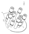
- FIG. 2 shows a device according to the invention in a perspective view of the tool side.
- the in FIG. 1 illustrated double feed output 20 includes a spindle drive 11, a gear 12 and two Vorschubabtriebe19 each with a cylinder 13, a piston 14, a splined shaft 15, two compressed-air connections 16 and an output 17 with tool holder 18th
- a spindle drive 11 drives by means of the gear 12 in each case the splines 15 of two feed drives 19, which are additionally axially displaceable by means of the piston 14 within the cylinder 13 in the direction of the axis of rotation of a spline shaft 15.
- the feed is realized by means of compressed air, by means of a first compressed air connection ( FIG. 1 above) 16 the leakage of the spline shaft 15 is realized from the cylinder and by means of a second compressed air connection ( FIG. 1 below) 16 the return of the spline 15 is realized in the cylinder.
- a hydraulically or electrically operated cylinder eg with ball screw
- FIG. 1 is clearly visible that one of the drives 17 is extended to a working position (right in the picture) and another output is in the rest position (left in the picture). If you assign several, for example, 5 of these Doppelvorschubabtriebe (consisting of two Vorschubabtrieben 19 and a spindle drive 11) circular, we obtain the screwing device according to the invention, so 2x5 feed gears 19 are arranged in a circle, wherein due to the distance of the feed gears 19 both circles different radii exhibit. It is thus possible to realize a screw which is suitable for mounting rims with different pitch circle diameter.
- the device according to the invention comprises five drives 17, each with a screwing tool (nut 21), which are arranged on an outer circumference, and five drives 17, each with one Screwing tool (nut 21), which are arranged on an inner circumference, wherein the radius of the inner circle is slightly smaller than that of the outer circle.
- the arranged on the outer circle drives 17 are in their working position (extended spline 15), arranged on the inner circle of drives are in their rest position (retracted spline 15).
- the splines 15 of the feed drives protrude even in their rest position from the transmission housing (spindle drives and feed outputs are not shown).
- the block drive 22 comprises the gearboxes for driving the spline shafts 15.
Landscapes
- Engineering & Computer Science (AREA)
- Mechanical Engineering (AREA)
- Details Of Spanners, Wrenches, And Screw Drivers And Accessories (AREA)
- Automobile Manufacture Line, Endless Track Vehicle, Trailer (AREA)
- Transmission Devices (AREA)
Claims (13)
- Procédé pour monter plusieurs moyens de fixation disposés notamment sur une piste circulaire en utilisant un dispositif de vissage (20) avec des entraînements de sortie d'avance (19) correspondant aux moyens de fixation avec à chaque fois un entraînement de sortie (17) comprenant un outil de vissage (18), des moyens (12) étant prévus dans le dispositif de vissage (20), lesquels moyens permettent le fonctionnement de deux entraînements de sortie d'avance (19) au moyen d'un entraînement à broche commun (11), le procédé comprenant les étapes suivantes :sortie des entraînements de sortie (17) hors d'une position de repos dans une position de travail et disposition de l'outil de vissage (18) sur les moyens de fixation avec vissage des moyens de fixation au moyen des entraînements de sortie (17),
caractérisé en cequ'un premier groupe de plusieurs entraînements de sortie d'avance (19), notamment un groupe de cinq, est disposé sur une première piste circulaire et un deuxième groupe de plusieurs entraînements de sortie d'avance (19), notamment un groupe de cinq, est disposé sur une deuxième piste circulaire, les rayons des pistes circulaires étant différents et un entraînement à broche (11) étant prévu pour l'entraînement de deux entraînements de sortie d'avance respectifs (19) qui sont disposés sur des pistes circulaires différentes. - Procédé selon la revendication 1, dans lequel les entraînements de sortie (17) reviennent à nouveau dans la position de repos après la fin de l'opération de vissage.
- Procédé selon la revendication 1 ou 2, dans lequel le dispositif de vissage (20) comprend des entraînements de sortie d'avance (19) qui sont disposés sur des pistes circulaires de diamètres différents, les entraînements de sortie (17) qui sont disposés sur la piste circulaire correspondant à une piste circulaire sur laquelle sont disposés les moyens de fixation étant toujours les seuls à quitter leur position de repos, et le nombre d'entraînements de sortie d'avance (19) correspondant au nombre de moyens de fixation.
- Procédé selon la revendication 3, les moyens de fixation étant des vis ou des écrous pour la fixation d'objets tels que des jantes, des roues dentées, des couronnes de différentiel, des volants d'inertie, des disques de frein et des jeux de roues, de préférence sur une carrosserie, un moteur ou une transmission d'un véhicule automobile.
- Dispositif de vissage (20) pour monter plusieurs moyens de fixation disposés notamment sur une piste circulaire, comprenant plusieurs entraînements à broche (11) pour l'entraînement de plusieurs entraînements de sortie d'avance (19) disposés notamment sur des pistes circulaires, les entraînements de sortie d'avance (19) comprenant des outils de vissage (18), des moyens (12) étant prévus, lesquels permettent le fonctionnement de deux entraînements de sortie d'avance (19) au moyen d'un entraînement à broche commun (11),
caractérisé en ce
qu'un premier groupe de plusieurs entraînements de sortie d'avance (19), notamment un groupe de cinq, est disposé sur une première piste circulaire et un deuxième groupe de plusieurs entraînements de sortie d'avance (19), notamment un groupe de cinq, est disposé sur une deuxième piste circulaire, les rayons des pistes circulaires étant différents et un entraînement à broche (11) étant prévu pour l'entraînement de deux entraînements de sortie d'avance respectifs (19) qui sont disposés sur des pistes circulaires différentes. - Dispositif selon la revendication 5, dans lequel un entraînement de sortie d'avance (19) est réalisé sous forme d'un cylindre (3) au moyen d'un actionneur à commande pneumatique, hydraulique ou électrique, la tige de piston du cylindre étant réalisée sous forme d'arbre (5) avec un porte-outil (8).
- Dispositif selon la revendication 6, dans lequel l'entraînement à broche (11) comprend un moteur électrique et dans lequel le moteur entraîne l'arbre (5) de l'entraînement de sortie d'avance (19) au moyen d'une transmission (12).
- Dispositif selon la revendication 7, dans lequel la transmission (12) se compose de plusieurs roues dentées, une première roue dentée étant disposée sur la broche de l'entraînement à broche (11) et transmettant la rotation de la broche à une deuxième roue dentée et cette deuxième roue dentée transmettant la rotation à une troisième roue dentée qui est disposée sur l'arbre (5).
- Dispositif selon la revendication 7, dans lequel la transmission (12) est réalisée au moyen de chaînes ou de courroies dentées afin de transmettre un couple.
- Dispositif selon l'une quelconque des revendications 6 à 9, dans lequel la broche respective d'un entraînement à broche est amenée en prise au moyen d'un accouplement électrique ou pneumatique.
- Dispositif selon l'une quelconque des revendications 5 à 10, dans lequel les mouvements de l'arbre et/ou le couple (5) peuvent être détectés au moyen d'un détecteur de valeur de mesure.
- Dispositif selon l'une quelconque des revendications 5 à 11, servant au montage de composants de véhicules automobiles.
- Dispositif pour fixer des objets tels que des jantes, des roues dentées, des couronnes de différentiel, des volants d'inertie, des disques de frein et des jeux de roues pour véhicules automobiles ou des composants de véhicules automobiles, comprenant un dispositif de vissage selon l'une quelconque des revendications 5 à 12, le dispositif étant notamment inclus dans une chaîne de montage de véhicules automobiles.
Applications Claiming Priority (2)
| Application Number | Priority Date | Filing Date | Title |
|---|---|---|---|
| DE102006017653A DE102006017653A1 (de) | 2006-04-12 | 2006-04-12 | Schraubsystem mit variabel zustellbaren Schraubspindeln |
| PCT/EP2007/001517 WO2007118544A1 (fr) | 2006-04-12 | 2007-02-22 | Système de vissage à broches de vissage à avance variable |
Publications (2)
| Publication Number | Publication Date |
|---|---|
| EP2010356A1 EP2010356A1 (fr) | 2009-01-07 |
| EP2010356B1 true EP2010356B1 (fr) | 2013-04-10 |
Family
ID=38059335
Family Applications (1)
| Application Number | Title | Priority Date | Filing Date |
|---|---|---|---|
| EP07722893.0A Active EP2010356B1 (fr) | 2006-04-12 | 2007-02-22 | Système de vissage à broches de vissage à avance variable |
Country Status (6)
| Country | Link |
|---|---|
| US (1) | US8316739B2 (fr) |
| EP (1) | EP2010356B1 (fr) |
| CA (1) | CA2648651C (fr) |
| DE (1) | DE102006017653A1 (fr) |
| ES (1) | ES2406951T3 (fr) |
| WO (1) | WO2007118544A1 (fr) |
Cited By (1)
| Publication number | Priority date | Publication date | Assignee | Title |
|---|---|---|---|---|
| DE102017117961A1 (de) | 2017-08-08 | 2019-02-14 | M B N- Maschinenbaubetriebe Neugersdorf GmbH | Verfahren und Vorrichtung zur Bereitstellung von Schrauben |
Families Citing this family (18)
| Publication number | Priority date | Publication date | Assignee | Title |
|---|---|---|---|---|
| DE102008007146B4 (de) * | 2008-01-31 | 2019-02-07 | Robert Bosch Gmbh | Montagewerkzeug |
| BRPI0907698B1 (pt) * | 2008-05-02 | 2019-12-10 | Dale Francis | sistema de chave de torque para multiparafuso ou porca, método para instalar uma coluna de riser a partir de uma plataforma e método para remover uma coluna de riser de uma plataforma |
| CN101428392B (zh) * | 2008-12-12 | 2011-09-21 | 奇瑞汽车股份有限公司 | 两轴电动拧紧机变距装置 |
| DE102009033989A1 (de) * | 2009-07-21 | 2011-02-03 | Thyssenkrupp Drauz Nothelfer Gmbh | Greifer zur Positionierung, Befestigung, Lageveränderung und/oder zum Wechseln von Werkzeugen auf einer Montagefläche |
| CN102152106B (zh) * | 2011-03-21 | 2012-07-25 | 山东同力达智能机械有限公司 | 一种crh2型动车组轴端螺母装配系统 |
| US20170015138A1 (en) * | 2015-07-19 | 2017-01-19 | Duarte Pamplona | Plural socket lug nut removal tool |
| DE102015213759A1 (de) * | 2015-07-22 | 2017-01-26 | Robert Bosch Gmbh | Handwerkzeug mit zwei Abtrieben |
| US9186761B1 (en) * | 2015-07-28 | 2015-11-17 | Mubarak A. H. F. H. Al-Motoutah | Multi-socket wrench |
| US20170157750A1 (en) * | 2015-12-07 | 2017-06-08 | David Koenes | Skateboard multi-purpose tool |
| CN106853582B (zh) * | 2016-12-30 | 2018-10-30 | 博众精工科技股份有限公司 | 一种双向锁紧机构 |
| US11472239B2 (en) * | 2017-08-19 | 2022-10-18 | Hongcai Wen | Apparatus and methods for robotically servicing a vehicle wheel |
| CN209007006U (zh) * | 2017-08-19 | 2019-06-21 | 文洪财 | 用于安装/拆卸圆形阵列螺纹紧固件的装置 |
| CN109290779A (zh) * | 2018-09-30 | 2019-02-01 | 丰业迪睦斯(芜湖)汽车部件有限公司 | 螺母自动安装力矩控制系统 |
| DE102019109964A1 (de) * | 2019-04-16 | 2020-10-22 | Bayerische Motoren Werke Aktiengesellschaft | Werkzeug sowie Verfahren zum gleichzeitigen Betätigen einer Vielzahl von Befestigungselementen |
| US12291875B1 (en) | 2019-12-11 | 2025-05-06 | Scepaniak IP Holdings, LLC | Commercial roofing screw machine |
| CN112318101B (zh) * | 2020-10-25 | 2022-12-20 | 山东奥德斯工业股份有限公司 | 一种汽车发动机飞轮拧紧装置 |
| CN113146181B (zh) * | 2021-04-23 | 2022-07-08 | 上海交通大学 | 自动取钉的定位装置 |
| CN113369875B (zh) * | 2021-06-18 | 2022-05-20 | 广州市日睛自动化机械有限公司 | 一种机油盖组装机 |
Family Cites Families (23)
| Publication number | Priority date | Publication date | Assignee | Title |
|---|---|---|---|---|
| US2069882A (en) | 1935-06-26 | 1937-02-09 | Michael O Meara J | Multiple power wrench |
| DE944930C (de) * | 1952-04-30 | 1956-06-28 | Fein C & E | Elektroschrauber |
| US2807972A (en) * | 1956-02-14 | 1957-10-01 | Thor Power Tool Co | Multiple unit assembly for rotary tools |
| US2964152A (en) * | 1956-03-15 | 1960-12-13 | Henry T M Rice | Fluid pressure operated releasable torque transmitting apparatus |
| US3319494A (en) * | 1964-10-22 | 1967-05-16 | Ingersoll Rand Co | Dual-speed fastener driving tool |
| US3439754A (en) | 1966-03-16 | 1969-04-22 | Chicago Pneumatic Tool Co | Apparatus for tightening screw connections to a precise torque |
| DE2112907C3 (de) * | 1971-03-17 | 1979-12-06 | Fried. Krupp Gmbh, 4300 Essen | Mehrfachschrauber mit mehreren in einem gemeinsamen Stützrahmen angeordneten Einzelschraubern |
| DE8009762U1 (de) * | 1980-04-10 | 1981-03-12 | Ruhrkohle Ag, 4300 Essen | Mehrspindelschrauber |
| US4542576A (en) * | 1983-07-26 | 1985-09-24 | Honda Giken Kogyo Kabushiki Kaisha | Replaceable head multi-spindle fastening apparatus |
| JPS6165731A (ja) * | 1984-09-07 | 1986-04-04 | Toyota Motor Corp | 多軸ナツトランナ |
| DE3434850C2 (de) * | 1984-09-22 | 1986-04-03 | Daimler-Benz Ag, 7000 Stuttgart | Mehrfachschrauber |
| DE3519352A1 (de) * | 1985-05-30 | 1986-12-04 | Robert Bosch Gmbh, 7000 Stuttgart | Schraubvorrichtung mit motorgetriebenem schraubendreher |
| US4909105A (en) * | 1985-11-19 | 1990-03-20 | Honda Giken Kogyo Kabushiki Kaisha | Automated nut driving apparatus |
| DD249219A1 (de) * | 1986-05-20 | 1987-09-02 | Dkk Scharfenstein Veb | Mehrfachschrauber |
| JPH05146975A (ja) * | 1991-11-26 | 1993-06-15 | Bridgestone Corp | 多軸電動オートナツトランナ |
| JPH08197347A (ja) * | 1995-01-24 | 1996-08-06 | Honda Motor Co Ltd | 多軸締付装置 |
| JPH08197440A (ja) * | 1995-01-24 | 1996-08-06 | Honda Motor Co Ltd | 多軸仮締め工具 |
| US6189418B1 (en) * | 1999-01-26 | 2001-02-20 | Dell Usa, L.P. | Multiple nut driver for computer assembly |
| US6134989A (en) * | 1999-02-03 | 2000-10-24 | Stevens; Gerald | Multi-lug nut driving device |
| DE20022490U1 (de) * | 2000-04-17 | 2002-01-17 | Reis GmbH & Co. Maschinenfabrik Obernburg, 63785 Obernburg | Montagezelle |
| JP2005246515A (ja) | 2004-03-02 | 2005-09-15 | Honda Motor Co Ltd | ねじ部材締結装置 |
| JP2006205321A (ja) * | 2005-01-28 | 2006-08-10 | Aisin Aw Co Ltd | ねじ部材締付け装置 |
| DE202005012869U1 (de) * | 2005-08-12 | 2005-10-27 | Gk-System Gmbh | Mehrfachschraubadapter |
-
2006
- 2006-04-12 DE DE102006017653A patent/DE102006017653A1/de not_active Withdrawn
-
2007
- 2007-02-22 CA CA2648651A patent/CA2648651C/fr not_active Expired - Fee Related
- 2007-02-22 EP EP07722893.0A patent/EP2010356B1/fr active Active
- 2007-02-22 ES ES07722893T patent/ES2406951T3/es active Active
- 2007-02-22 WO PCT/EP2007/001517 patent/WO2007118544A1/fr not_active Ceased
- 2007-02-22 US US12/296,214 patent/US8316739B2/en not_active Expired - Fee Related
Cited By (4)
| Publication number | Priority date | Publication date | Assignee | Title |
|---|---|---|---|---|
| DE102017117961A1 (de) | 2017-08-08 | 2019-02-14 | M B N- Maschinenbaubetriebe Neugersdorf GmbH | Verfahren und Vorrichtung zur Bereitstellung von Schrauben |
| WO2019029898A1 (fr) | 2017-08-08 | 2019-02-14 | M B N - Maschinenbaubetriebe Neugersdorf Gmbh | Procédé et dispositif de fourniture de vis |
| US11253959B2 (en) * | 2017-08-08 | 2022-02-22 | M B N—Maschinenbaubetriebe Neugersdorf Gmbh | Method and device for furnishing screws |
| DE102017117961B4 (de) | 2017-08-08 | 2023-04-27 | M B N- Maschinenbaubetriebe Neugersdorf GmbH | Verfahren und Vorrichtung zur Bereitstellung von Schrauben |
Also Published As
| Publication number | Publication date |
|---|---|
| WO2007118544A1 (fr) | 2007-10-25 |
| US20100162854A1 (en) | 2010-07-01 |
| US8316739B2 (en) | 2012-11-27 |
| CA2648651C (fr) | 2012-08-21 |
| EP2010356A1 (fr) | 2009-01-07 |
| ES2406951T3 (es) | 2013-06-10 |
| CA2648651A1 (fr) | 2007-10-25 |
| DE102006017653A1 (de) | 2007-10-18 |
Similar Documents
| Publication | Publication Date | Title |
|---|---|---|
| EP2010356A1 (fr) | Système de vissage à broches de vissage à avance variable | |
| EP2756893B1 (fr) | Appareil de traitement des matériaux, notamment une machine de déformage | |
| EP1423231B1 (fr) | Poste de vissage | |
| EP3829817B1 (fr) | Dispositif de vissage, moyen de génération de couple d'entraînement, système de vissage et procédé de contrôle du couple | |
| DE102013216449A1 (de) | Industrieroboter mit wenigstens einem Antrieb | |
| DE102014222049A1 (de) | Gewindefertigung unter Verwendung eines Schlagschraubers | |
| DE3414957A1 (de) | Anti-spiel-mechanismus fuer einen maschinenantrieb | |
| EP1514646B1 (fr) | Appareil pour la pose de rivets-écrous borgnes | |
| EP3201072A1 (fr) | Dispositif de permutation pour modules de serrage ou de centrage | |
| EP3153280B1 (fr) | Outil avec interface universelle pour interface d'entraînement | |
| DE102007023807B4 (de) | Umschaltmittel für Schrauber mit zwei Abtrieben | |
| DE102014008377A1 (de) | Radflansch-Gelenkgehäuseanordnung für eine Seitenwelle eines Fahrzeugs | |
| DE102017113066B3 (de) | Verfahren zum Schlagverfestigen von Übergangsradien einer Kurbelwelle | |
| DE102010035551A1 (de) | Werkzeug für einen Roboter sowie Verfahren zum Herstellen einer Schraubverbindung | |
| DE102008007146B4 (de) | Montagewerkzeug | |
| DE102017113065B3 (de) | Verfahren und Vorrichtung zum Schlagverfestigen von Übergangsradien einer Kurbelwelle | |
| DE102009021256B4 (de) | Angetriebene Schraubvorrichtung für mehrere Schraubweiten | |
| DE102017212888A1 (de) | Schraubsystem und Verfahren zum Ableiten von Schraubreaktionskräften von einem Roboter | |
| DE19718257C2 (de) | Profilwalzmaschine zum Walzen eines rotationssymmetrischen Werkstücks mit einem präzisen Außenprofil | |
| WO2018228795A1 (fr) | Procédé et dispositif de consolidation par percussion de rayons de transition d'un vilebrequin | |
| EP2095892A1 (fr) | Machine à laminer des profilés | |
| DE102021111646A1 (de) | Linearaktuator für eine Achslenkung, Verfahren zur Montage des Linearaktuators und Achslenkung | |
| DE19950715A1 (de) | Bearbeitungskopf für eine Maschine zum spanabnehmenden Bearbeiten von Paneelen | |
| DE102011119890B4 (de) | 1Werkzeug, insbesondere Schraubwerkzeugmit schwenkbarem Winkelkopf | |
| DE102014110382B4 (de) | Spannungswellengetriebe und Verfahren zum Herstellen eines Spannungswellengetriebes |
Legal Events
| Date | Code | Title | Description |
|---|---|---|---|
| PUAI | Public reference made under article 153(3) epc to a published international application that has entered the european phase |
Free format text: ORIGINAL CODE: 0009012 |
|
| 17P | Request for examination filed |
Effective date: 20081112 |
|
| AK | Designated contracting states |
Kind code of ref document: A1 Designated state(s): AT BE BG CH CY CZ DE DK EE ES FI FR GB GR HU IE IS IT LI LT LU LV MC NL PL PT RO SE SI SK TR |
|
| AX | Request for extension of the european patent |
Extension state: AL BA HR MK RS |
|
| DAX | Request for extension of the european patent (deleted) | ||
| RBV | Designated contracting states (corrected) |
Designated state(s): BE DE ES GB PL |
|
| 17Q | First examination report despatched |
Effective date: 20090806 |
|
| GRAP | Despatch of communication of intention to grant a patent |
Free format text: ORIGINAL CODE: EPIDOSNIGR1 |
|
| GRAS | Grant fee paid |
Free format text: ORIGINAL CODE: EPIDOSNIGR3 |
|
| GRAA | (expected) grant |
Free format text: ORIGINAL CODE: 0009210 |
|
| AK | Designated contracting states |
Kind code of ref document: B1 Designated state(s): BE DE ES GB PL |
|
| REG | Reference to a national code |
Ref country code: GB Ref legal event code: FG4D Free format text: NOT ENGLISH |
|
| REG | Reference to a national code |
Ref country code: DE Ref legal event code: R096 Ref document number: 502007011596 Country of ref document: DE Effective date: 20130606 |
|
| REG | Reference to a national code |
Ref country code: ES Ref legal event code: FG2A Ref document number: 2406951 Country of ref document: ES Kind code of ref document: T3 Effective date: 20130610 |
|
| PG25 | Lapsed in a contracting state [announced via postgrant information from national office to epo] |
Ref country code: PL Free format text: LAPSE BECAUSE OF FAILURE TO SUBMIT A TRANSLATION OF THE DESCRIPTION OR TO PAY THE FEE WITHIN THE PRESCRIBED TIME-LIMIT Effective date: 20130410 |
|
| PLBE | No opposition filed within time limit |
Free format text: ORIGINAL CODE: 0009261 |
|
| STAA | Information on the status of an ep patent application or granted ep patent |
Free format text: STATUS: NO OPPOSITION FILED WITHIN TIME LIMIT |
|
| 26N | No opposition filed |
Effective date: 20140113 |
|
| REG | Reference to a national code |
Ref country code: DE Ref legal event code: R097 Ref document number: 502007011596 Country of ref document: DE Effective date: 20140113 |
|
| BERE | Be: lapsed |
Owner name: ROBERT BOSCH G.M.B.H. Effective date: 20140228 |
|
| GBPC | Gb: european patent ceased through non-payment of renewal fee |
Effective date: 20140222 |
|
| PG25 | Lapsed in a contracting state [announced via postgrant information from national office to epo] |
Ref country code: BE Free format text: LAPSE BECAUSE OF NON-PAYMENT OF DUE FEES Effective date: 20140228 Ref country code: GB Free format text: LAPSE BECAUSE OF NON-PAYMENT OF DUE FEES Effective date: 20140222 |
|
| REG | Reference to a national code |
Ref country code: ES Ref legal event code: FD2A Effective date: 20150331 |
|
| PG25 | Lapsed in a contracting state [announced via postgrant information from national office to epo] |
Ref country code: ES Free format text: LAPSE BECAUSE OF NON-PAYMENT OF DUE FEES Effective date: 20140223 |
|
| PGFP | Annual fee paid to national office [announced via postgrant information from national office to epo] |
Ref country code: DE Payment date: 20260427 Year of fee payment: 20 |