EP2010694B1 - Dispositif et procédé de commande de la température de surface d'un substrat dans une chambre de traitement - Google Patents
Dispositif et procédé de commande de la température de surface d'un substrat dans une chambre de traitement Download PDFInfo
- Publication number
- EP2010694B1 EP2010694B1 EP07728207A EP07728207A EP2010694B1 EP 2010694 B1 EP2010694 B1 EP 2010694B1 EP 07728207 A EP07728207 A EP 07728207A EP 07728207 A EP07728207 A EP 07728207A EP 2010694 B1 EP2010694 B1 EP 2010694B1
- Authority
- EP
- European Patent Office
- Prior art keywords
- substrate
- substrate holder
- gas
- temperature
- heat
- Prior art date
- Legal status (The legal status is an assumption and is not a legal conclusion. Google has not performed a legal analysis and makes no representation as to the accuracy of the status listed.)
- Not-in-force
Links
Images


Classifications
-
- C—CHEMISTRY; METALLURGY
- C23—COATING METALLIC MATERIAL; COATING MATERIAL WITH METALLIC MATERIAL; CHEMICAL SURFACE TREATMENT; DIFFUSION TREATMENT OF METALLIC MATERIAL; COATING BY VACUUM EVAPORATION, BY SPUTTERING, BY ION IMPLANTATION OR BY CHEMICAL VAPOUR DEPOSITION, IN GENERAL; INHIBITING CORROSION OF METALLIC MATERIAL OR INCRUSTATION IN GENERAL
- C23C—COATING METALLIC MATERIAL; COATING MATERIAL WITH METALLIC MATERIAL; SURFACE TREATMENT OF METALLIC MATERIAL BY DIFFUSION INTO THE SURFACE, BY CHEMICAL CONVERSION OR SUBSTITUTION; COATING BY VACUUM EVAPORATION, BY SPUTTERING, BY ION IMPLANTATION OR BY CHEMICAL VAPOUR DEPOSITION, IN GENERAL
- C23C16/00—Chemical coating by decomposition of gaseous compounds, without leaving reaction products of surface material in the coating, i.e. chemical vapour deposition [CVD] processes
- C23C16/44—Chemical coating by decomposition of gaseous compounds, without leaving reaction products of surface material in the coating, i.e. chemical vapour deposition [CVD] processes characterised by the method of coating
- C23C16/458—Chemical coating by decomposition of gaseous compounds, without leaving reaction products of surface material in the coating, i.e. chemical vapour deposition [CVD] processes characterised by the method of coating characterised by the method used for supporting substrates in the reaction chamber
- C23C16/4582—Rigid and flat substrates, e.g. plates or discs
- C23C16/4583—Rigid and flat substrates, e.g. plates or discs the substrate being supported substantially horizontally
- C23C16/4584—Rigid and flat substrates, e.g. plates or discs the substrate being supported substantially horizontally the substrate being rotated
-
- C—CHEMISTRY; METALLURGY
- C23—COATING METALLIC MATERIAL; COATING MATERIAL WITH METALLIC MATERIAL; CHEMICAL SURFACE TREATMENT; DIFFUSION TREATMENT OF METALLIC MATERIAL; COATING BY VACUUM EVAPORATION, BY SPUTTERING, BY ION IMPLANTATION OR BY CHEMICAL VAPOUR DEPOSITION, IN GENERAL; INHIBITING CORROSION OF METALLIC MATERIAL OR INCRUSTATION IN GENERAL
- C23C—COATING METALLIC MATERIAL; COATING MATERIAL WITH METALLIC MATERIAL; SURFACE TREATMENT OF METALLIC MATERIAL BY DIFFUSION INTO THE SURFACE, BY CHEMICAL CONVERSION OR SUBSTITUTION; COATING BY VACUUM EVAPORATION, BY SPUTTERING, BY ION IMPLANTATION OR BY CHEMICAL VAPOUR DEPOSITION, IN GENERAL
- C23C16/00—Chemical coating by decomposition of gaseous compounds, without leaving reaction products of surface material in the coating, i.e. chemical vapour deposition [CVD] processes
- C23C16/44—Chemical coating by decomposition of gaseous compounds, without leaving reaction products of surface material in the coating, i.e. chemical vapour deposition [CVD] processes characterised by the method of coating
- C23C16/458—Chemical coating by decomposition of gaseous compounds, without leaving reaction products of surface material in the coating, i.e. chemical vapour deposition [CVD] processes characterised by the method of coating characterised by the method used for supporting substrates in the reaction chamber
-
- C—CHEMISTRY; METALLURGY
- C23—COATING METALLIC MATERIAL; COATING MATERIAL WITH METALLIC MATERIAL; CHEMICAL SURFACE TREATMENT; DIFFUSION TREATMENT OF METALLIC MATERIAL; COATING BY VACUUM EVAPORATION, BY SPUTTERING, BY ION IMPLANTATION OR BY CHEMICAL VAPOUR DEPOSITION, IN GENERAL; INHIBITING CORROSION OF METALLIC MATERIAL OR INCRUSTATION IN GENERAL
- C23C—COATING METALLIC MATERIAL; COATING MATERIAL WITH METALLIC MATERIAL; SURFACE TREATMENT OF METALLIC MATERIAL BY DIFFUSION INTO THE SURFACE, BY CHEMICAL CONVERSION OR SUBSTITUTION; COATING BY VACUUM EVAPORATION, BY SPUTTERING, BY ION IMPLANTATION OR BY CHEMICAL VAPOUR DEPOSITION, IN GENERAL
- C23C16/00—Chemical coating by decomposition of gaseous compounds, without leaving reaction products of surface material in the coating, i.e. chemical vapour deposition [CVD] processes
- C23C16/44—Chemical coating by decomposition of gaseous compounds, without leaving reaction products of surface material in the coating, i.e. chemical vapour deposition [CVD] processes characterised by the method of coating
- C23C16/46—Chemical coating by decomposition of gaseous compounds, without leaving reaction products of surface material in the coating, i.e. chemical vapour deposition [CVD] processes characterised by the method of coating characterised by the method used for heating the substrate
-
- C—CHEMISTRY; METALLURGY
- C23—COATING METALLIC MATERIAL; COATING MATERIAL WITH METALLIC MATERIAL; CHEMICAL SURFACE TREATMENT; DIFFUSION TREATMENT OF METALLIC MATERIAL; COATING BY VACUUM EVAPORATION, BY SPUTTERING, BY ION IMPLANTATION OR BY CHEMICAL VAPOUR DEPOSITION, IN GENERAL; INHIBITING CORROSION OF METALLIC MATERIAL OR INCRUSTATION IN GENERAL
- C23C—COATING METALLIC MATERIAL; COATING MATERIAL WITH METALLIC MATERIAL; SURFACE TREATMENT OF METALLIC MATERIAL BY DIFFUSION INTO THE SURFACE, BY CHEMICAL CONVERSION OR SUBSTITUTION; COATING BY VACUUM EVAPORATION, BY SPUTTERING, BY ION IMPLANTATION OR BY CHEMICAL VAPOUR DEPOSITION, IN GENERAL
- C23C16/00—Chemical coating by decomposition of gaseous compounds, without leaving reaction products of surface material in the coating, i.e. chemical vapour deposition [CVD] processes
- C23C16/44—Chemical coating by decomposition of gaseous compounds, without leaving reaction products of surface material in the coating, i.e. chemical vapour deposition [CVD] processes characterised by the method of coating
- C23C16/46—Chemical coating by decomposition of gaseous compounds, without leaving reaction products of surface material in the coating, i.e. chemical vapour deposition [CVD] processes characterised by the method of coating characterised by the method used for heating the substrate
- C23C16/463—Cooling of the substrate
- C23C16/466—Cooling of the substrate using thermal contact gas
-
- C—CHEMISTRY; METALLURGY
- C23—COATING METALLIC MATERIAL; COATING MATERIAL WITH METALLIC MATERIAL; CHEMICAL SURFACE TREATMENT; DIFFUSION TREATMENT OF METALLIC MATERIAL; COATING BY VACUUM EVAPORATION, BY SPUTTERING, BY ION IMPLANTATION OR BY CHEMICAL VAPOUR DEPOSITION, IN GENERAL; INHIBITING CORROSION OF METALLIC MATERIAL OR INCRUSTATION IN GENERAL
- C23C—COATING METALLIC MATERIAL; COATING MATERIAL WITH METALLIC MATERIAL; SURFACE TREATMENT OF METALLIC MATERIAL BY DIFFUSION INTO THE SURFACE, BY CHEMICAL CONVERSION OR SUBSTITUTION; COATING BY VACUUM EVAPORATION, BY SPUTTERING, BY ION IMPLANTATION OR BY CHEMICAL VAPOUR DEPOSITION, IN GENERAL
- C23C16/00—Chemical coating by decomposition of gaseous compounds, without leaving reaction products of surface material in the coating, i.e. chemical vapour deposition [CVD] processes
- C23C16/44—Chemical coating by decomposition of gaseous compounds, without leaving reaction products of surface material in the coating, i.e. chemical vapour deposition [CVD] processes characterised by the method of coating
- C23C16/52—Controlling or regulating the coating process
-
- C—CHEMISTRY; METALLURGY
- C30—CRYSTAL GROWTH
- C30B—SINGLE-CRYSTAL GROWTH; UNIDIRECTIONAL SOLIDIFICATION OF EUTECTIC MATERIAL OR UNIDIRECTIONAL DEMIXING OF EUTECTOID MATERIAL; REFINING BY ZONE-MELTING OF MATERIAL; PRODUCTION OF A HOMOGENEOUS POLYCRYSTALLINE MATERIAL WITH DEFINED STRUCTURE; SINGLE CRYSTALS OR HOMOGENEOUS POLYCRYSTALLINE MATERIAL WITH DEFINED STRUCTURE; AFTER-TREATMENT OF SINGLE CRYSTALS OR A HOMOGENEOUS POLYCRYSTALLINE MATERIAL WITH DEFINED STRUCTURE; APPARATUS THEREFOR
- C30B25/00—Single-crystal growth by chemical reaction of reactive gases, e.g. chemical vapour-deposition growth
- C30B25/02—Epitaxial-layer growth
- C30B25/10—Heating of the reaction chamber or the substrate
-
- C—CHEMISTRY; METALLURGY
- C30—CRYSTAL GROWTH
- C30B—SINGLE-CRYSTAL GROWTH; UNIDIRECTIONAL SOLIDIFICATION OF EUTECTIC MATERIAL OR UNIDIRECTIONAL DEMIXING OF EUTECTOID MATERIAL; REFINING BY ZONE-MELTING OF MATERIAL; PRODUCTION OF A HOMOGENEOUS POLYCRYSTALLINE MATERIAL WITH DEFINED STRUCTURE; SINGLE CRYSTALS OR HOMOGENEOUS POLYCRYSTALLINE MATERIAL WITH DEFINED STRUCTURE; AFTER-TREATMENT OF SINGLE CRYSTALS OR A HOMOGENEOUS POLYCRYSTALLINE MATERIAL WITH DEFINED STRUCTURE; APPARATUS THEREFOR
- C30B25/00—Single-crystal growth by chemical reaction of reactive gases, e.g. chemical vapour-deposition growth
- C30B25/02—Epitaxial-layer growth
- C30B25/16—Controlling or regulating
Definitions
- the invention relates to a method for controlling the surface temperature of a substrate supported in a process chamber of a CVD reactor by a substrate holder carrier on a dynamic gas cushion formed by a gas flow substrate holder, wherein the heat supply to the substrate takes place at least partially by heat conduction through the gas cushion.
- the invention further relates to a device for carrying out the method with a process chamber, a substrate holder carrier arranged therein, one or more substrate holders, a heater for heating the substrate holder carrier, an optical temperature measuring device for measuring the surface temperatures of the substrates resting on the substrate holders and with a gas supply line Supply of a gas stream for generating a dynamic gas cushion between the substrate holder carrier and a substrate holder.
- a generic device and a generic method describes the US 5,318,801 , Described there is a CVD reactor in which a substrate holder rests on a gas cushion in a bearing opening of a substrate holder carrier.
- the gas cushion is formed by a gas flow of different heat-conducting gases.
- the surface temperature of the substrate holder should be varied by varying the gas composition. For this purpose, the surface temperature of the substrate holder is measured at one point.
- the DE 100 56 029 A1 describes a CVD reactor for depositing III-V semiconductor layers on III-V substrates.
- the substrates lie on substrate holders, which have the shape of circular cylindrical disks. These substrate holders are in a satellite-like arrangement on a substrate holder carrier.
- the substrate holder carrier has bearing recesses which receive the substrate holders. From the bottom of the bearing recesses escape gas streams, which hold the substrate holder on a gas cushion in suspension. By a corresponding direction of the gas flow emerging from bottom-side nozzles, the substrate holders are set in rotation. In such a CVD reactor, not only the substrate holders may rotate relative to the substrate holder carrier. It is also envisaged that the substrate holder carrier itself rotates about its own axis.
- the substrate holder carrier as well as the substrate holder can be made of graphite.
- the surface temperature is measured by a pyrometer.
- the process container ceiling opposite the substrate holder carrier has an opening.
- the pyrometer is connected to a control device. This control device first of all determines the average surface temperature of the substrate. This should be within a certain setpoint range.
- the heat for generating the surface temperature of the substrate is supplied from below via the substrate holder carrier. For this purpose, the latter is heated from below. The heat is transferred to the substrate holder via heat radiation as well as via heat conduction via the gap forming the dynamic gas cushion.
- This heat is conducted from the substrate holder bottom to the substrate holder top on which the substrate lies.
- the substrate is in full-surface contact with the surface of the substrate holder.
- the substrate is often just at the edge or only in the center on the substrate holder. This is a consequence of a thermally or structurally related curvature of the substrate.
- the height of the gas cushion is influenced.
- the thermal conductivity of this gas gap is influenced.
- the gas flow can thus influence the heat transfer to the substrate.
- the mean surface temperature of the substrate can be sensitively influenced.
- the lateral temperature profile on the surface ie temperature inhomogeneities and in particular horizontal gradients, can only be influenced to a limited extent by this method.
- a device for depositing layers on substrates in which a plurality of substrate holders eino in cup-shaped recesses of a substrate holder carrier.
- the substrate holders are each supported by a gas cushion.
- T2 From the DE 696 29 980 T2 is a method of controlling the temperature for depositing a material previously known.
- the substrate is above a cooling block. There is a gap between substrate and cooling block, which is flushed with gases of different thermal conductivity.
- the DE 69117 824 T2 describes a process in which the backside of a substrate is rinsed with a mixture of argon and hydrogen.
- the US 5,683,759 describes a method for depositing polycrystalline diamonds on a substrate, wherein a substrate holder has different deep annular grooves.
- a CVD device in which the substrates rest on a rotatable substrate holder.
- the substrate holder rests on a gas cushion.
- the invention is based on the object starting from the generic state of the art to improve the lateral homogeneity of the surface temperature of the substrate.
- the gas stream forming the gas cushion is formed by two or more gases with different specific heat conductivity.
- the thermal conductivity of the dynamic gas cushion is varied by the composition of this gas stream.
- the thermal conductivity can also be (additionally) varied by increasing the flow rate.
- the thermal conductivity of the dynamic gas cushion With the variation of the thermal conductivity of the dynamic gas cushion, a fine adjustment of the course of the temperature on the substrate holder surface is thus possible.
- the inventive possibility of fine adjustment of the thermal conductivity thus forms the possibility to influence the temperature without changing the thickness of the gas cushion.
- the two strongly thermally conductive gases also have very different viscosities.
- the substrate holder has a thermal conductivity or the substrate holder and the bearing recess have a shape such that the surface temperature of the substrate holder with the use of only one of the two gases has a lateral inhomogeneity, compensated by changing the composition and in particular is overcompensated.
- Thermal conductivity of the substrate holder may have a radial inhomogeneity. However, it is provided that the substrate holder has a rotational symmetry with respect to the thermal conductivity.
- the facing each other, the gas cushion delimiting surfaces of substrate holder base on the one hand and the bottom surface of the bearing recess on the other hand also have a particular particular rotationally symmetric structure. These two surfaces may have a shape that deviates from the shape of a plane.
- the gas cushion may have different thicknesses at different radial positions.
- the substrate holder surface temperature in the middle is lower than at the edge.
- hydrogen is used as gas cushion generating gas, then the surface temperature of the substrate holder is higher in the middle than at the edge.
- the associated local changes in the heat transport properties from the substrate holder to the substrate can be compensated by a corresponding change in the gas composition. If, for example, the center of the substrate lifts off from the substrate holder as a result of a thermal deflection of the substrate, the heat transfer in the center can be increased by varying the gas composition. In an analogous manner, it is possible to compensate for the reduced temperature transfer at the edge, when the edges of the substrate stand out from the substrate holder surface due to a curvature of the substrate. Optimal such effects can be compensated by the fact that when using only a highly thermally conductive gas, the central region of the
- Substrate holder is warmer than the edge region or that when only a weak heat-conducting gas is used, the central region of the substrate holder is colder than the edge region. It is also possible to use substrate holders whose heat conduction properties are locally different in the axial direction. Thus, the heat-conducting property in the axial direction in the center may be different than at the edge of the substrate holder. This also applies to the heat radiation properties which are responsible for the energy transfer by way of heat radiation. These too can be different at different radial positions.
- the thermal radiation properties are essentially surface properties. It is thus provided that the surface of the bottom of the bearing recess and the surface of the substrate holder underside can have locally different heat radiation properties.
- the substrate holders have different material thicknesses in the radial direction.
- the substrate holder may be thinner in the middle than at the edge.
- the underside of the substrate holder may have a curvature.
- the bottom of the bearing recess can be curved either convex or concave.
- the substrate holder has a stepped recess on its underside.
- the device for carrying out the method substantially corresponds to that of the DE 10056029 A1 is described.
- the method according to the invention can also be carried out with a variation of the gas flows for varying the height of the gas cushion.
- the device for carrying out the method has a heater arranged below the substrate holder carrier.
- This can be a resistance heater.
- the surface temperature of the substrate resting on the substrate holder is constantly measured.
- an average temperature is measured.
- the radial dependence of the temperature is detectable.
- a pyrometer is sufficient for measuring the temperature when the substrate holder carrier is rotated about its axis.
- the measured values of the pyrometer are fed to a control device.
- This controller controls mass flowmeters that control the gas composition of the gas stream that forms the gas cushion.
- the total gas flow per time is kept constant, so that the height of the gas cushion remains constant. But it is also possible that in addition by varying the total flow, the height of the gas cushion is varied.
- the method according to the invention is carried out in a process chamber 12 of a CVD reactor.
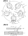
- the process chamber 12 is located between a horizontally extending substrate holder carrier 1, which has a circular outline and can be driven in rotation about its axis 14, and a process chamber ceiling 10 located parallel above the substrate holder carrier 1.
- the process chamber is located between the ceiling 10 and substrate holder carrier 1
- the substrate holder carrier 1 is heated from below by means of a resistance heater 24.
- On the upper side of the substrate holder carrier 1, a total of five bearing recesses 20 are provided.
- In each of the cup-shaped bearing recesses 20 is a circular disk-shaped substrate holder 2 a.
- In the bottom 21 of the bearing recess 20 are spiral grooves 7, in which gas supply lines 6 open.
- the gas emerging from the spiral grooves 7 raises the substrate holder 2 and stores it on a dynamic gas cushion 8.
- the gases exit the spiral groove 7 with a certain direction suitable for rotating the substrate holder 2 so as to rotate about its own axis rotates.
- On each of the substrate holder 2 is a substrate 9.
- the entire process chamber is in a reactor housing, not shown, and is hermetically sealed off from the environment, so that the process chamber 12 can be evacuated.
- process gases are required which are introduced into the process chamber 12 by feed lines (not shown). These process gases may include organometallic compounds. They can also contain hydrides. They can also be metal chlorides.
- a monocrystalline layer is to be deposited. These may be materials of the main group IV or materials of the III and V main group or materials of the II and VI main group.
- the substrate 9 may be made of any suitable material. It may be a non-conductor or be a semiconductor. Ideally, lattice-matched layers are deposited on the monocrystalline surface of the substrate. Ideally, the deposited layers and the substrate have the same thermal expansion coefficient. As a rule, the layers are not 100% lattice-matched.
- the individual layers also have different thermal expansion coefficients.
- the layers have larger or smaller coefficients of thermal expansion.
- stresses occur which lead to a bulging of the substrate.
- the deposition of non-lattice-matched layers can lead to tension and thus bulges of the substrate 9.
- the center of the substrate 9 can bulge upwards or downwards.
- the curvature of the substrate 9 during a process can also reverse, so that in one process section, only the central region of the substrate 9 touchingly rests on the surface of the substrate holder 2 and in another process section only the edge of the substrate 9 touchingly rests on the surface of the substrate holder 2. This has the consequence that the heat flow from the surface of the substrate holder 2 towards the substrate 9 is laterally different and varies over time.
- the process chamber 12 is heated only from below, there forms a vertical temperature gradient. This means that the temperature in the gas phase above the substrate 9 decreases with increasing distance from the substrate holder 2. Because of the lack of contact of the substrate 9 at individual points to the surface of the substrate holder 2, there is a reduced heat transfer from the substrate holder 2 to the substrate 9. This has the consequence that certain areas of the substrate 9 are colder than other areas. This is not wanted. Rather, one is desirous over the entire surface of the Substrate 9 constant surface temperature, so that the temperature gradient in the horizontal direction is minimal.
- the isotherm immediately above the surface of the substrate 9 should be as flat as possible. The substrate surface ideally should lie on an isotherm.
- the heat transfer from the substrate holder carrier 1 to the substrate holder 2 takes place essentially via the dynamic gas cushion 8.
- both the heat radiation from the bottom 21 of the bearing recess 20 to the underside of the substrate holder 2 and the heat conduction via the heat-conducting gas, which forms the gas cushion 8 plays a role ,
- the heat transfer can be influenced by radiant heat.
- the heat transfer by heat conduction can be varied by varying the height of the dynamic gas cushion 8.
- the total gas flow through the supply line 6 can be increased or decreased.
- this is done by means of a variation of the composition of the gas which generates the dynamic gas cushion 8.
- Two gases 17,18 are used which have a large difference in their specific thermal conductivity.
- highly thermally conductive hydrogen 17 can be mixed with low thermal conductivity nitrogen 18.
- mass flow controllers 15, 16 are used individually for each of the two gases 17, 18.
- other gas mixtures, in particular suitable noble gases such as argon, helium, etc., can also be used.
- the two different gases 17, 18 are combined with one another Feed line 6 passed into the bearing recesses 20.
- a control device 19 For adjusting the gas flows 15,16 a control device 19 is provided.
- This control device 19 receives its input data from a pyrometer 3, which measures the substrate surface temperature through an opening 11. An average surface temperature is measured as the substrate holder 2 rotates. Due to the rotation of the substrate holder carrier 1, one substrate holder 2 passes under the opening 11 one after the other. Since this has the same radial distance from the axis of rotation 14 as the axis of rotation of the substrate holder 2, a Diagonaltemperaturverlauf is measured, as for example in the FIG. 4 is shown.
- the substrate holder 2 can be designed so that when using only a weak heat conductive gas 18, the edge region of the substrate holder surface is hotter than the central region. This is in the FIG. 4 represented by the curve I. If the mixing ratio of the gas is changed in such a way that the heat conductivity of the gas is increased by adding more hydrogen 17 and withdrawing nitrogen 18, the central area of the surface of the substrate holder carrier 1 heats up to a greater extent. This is indicated by the curve II and due to a surprising effect. A further increase in the thermal conductivity of the gas cushion 8 then leads to the temperature of the substrate holder surface being substantially equal over the entire radial extent, as shown in the curve III. This is a desired state when the substrate 9 rests flat on the surface of the substrate holder 2 in an ideal manner.
- a temperature profile is achieved, as represented by the curve IV. If only hydrogen 17 flows through the supply line 6, a temperature profile, such as curve V, can be achieved.
- a temperature profile of the substrate holder surface as represented by the curves I and II, is required when the substrate 9 rests only with its central region on the surface of the substrate holder 2. Then, the temperature of the substrate holder 2 in the edge region must be higher in order to compensate for the reduced heat conduction to the substrate 9.
- the temperature profiles according to the curves IV and V are of importance when the substrate 9 rests on the surface of the substrate holder 2 only with the edge region. Now, the reduced heat conduction in the central area must be compensated by a higher surface temperature.
- the substrate holder shown has the underside of the substrate holder 2 has a recess 13. This is a central, cup-shaped recess 13, which leads to an increase in the height of the gas cushion 8. This has a reduced heat transfer by conduction from the bottom 21 to the substrate holder 2 result.
- the associated inhomogenization of the surface temperature can be compensated by an appropriate composition of the gases.
- this recess 13 is shown as a trough.
- the bottom of the trough 13 passes without a step in the flat annular surface of the underside of the substrate holder 2.
- a combination of the variation of the gas composition and a concomitant increase in the gas pressure can influence not only the course of the surface temperature but also the absolute value of the surface temperature. This is it is possible to lower or increase the edge temperature with respect to the central temperature around a constant mean value, wherein the edge temperature of the substrate holder 2 may be both above and below the central temperature of the substrate surface.
- the temperature profile on the substrate holder surface is ideally set by the control device 19 via the variation of the mass flows 15, 16 in such a way that the substrate surface has the same temperature as possible at each point.
Landscapes
- Chemical & Material Sciences (AREA)
- Chemical Kinetics & Catalysis (AREA)
- General Chemical & Material Sciences (AREA)
- Engineering & Computer Science (AREA)
- Materials Engineering (AREA)
- Metallurgy (AREA)
- Organic Chemistry (AREA)
- Mechanical Engineering (AREA)
- Crystallography & Structural Chemistry (AREA)
- Chemical Vapour Deposition (AREA)
Claims (16)
- Procédé de commande de la température de surface d'au moins un substrat (9) qui est placé dans une cavité de logement (20) d'un support de porte-substrat (11) se trouvant dans une chambre de réaction (12) d'un réacteur CVD et qui repose sur un porte-substrat (2) supporté par des coussins de gaz dynamiques (8) formés par un flux de gaz, le flux de gaz qui réalise le coussin de gaz (8) entre la surface de fond de la cavité de logement (20) et le côté inférieur du porte-substrat (2) étant formé par deux gaz ou plus (17, 18) présentant des conductivités thermiques spécifiques différentes, et l'amenée de chaleur au substrat (9) étant effectuée au moins partiellement en dirigeant de la chaleur sur le coussin de gaz et la température de surface du substrat étant mesurée à la surface du substrat et la propriété de conductivité thermique du coussin de gaz étant influencée en faisant varier la composition du gaz, caractérisé en ce que la température de surface du substrat est mesurée en un grand nombre d'endroits et les écarts de ces températures par rapport d'une valeur moyenne étant évités en faisant varier la composition du gaz en fonction des températures de surface mesurées, la conductivité thermique du porte-substrat (2) étant choisie et le côté inférieur du porte-substrat (2) ainsi que la surface de fond de la cavité de logement (20) étant conformés de telle sorte que la température de surface du substrat présente, lorsque l'on n'utilise qu'un seul des deux gaz (17, 18), une hétérogénéité latérale à symétrie de révolution qui est compensée ou surcompensée en faisant varier la composition du flux de gaz.
- Procédé selon la revendication 1, caractérisé en ce que, en faisant varier la composition du gaz, on modifie la courbe de température latérale à la surface du porte-substrat (2) de sorte que la température à la surface du substrat est constante sur sensiblement toute la surface du substrat.
- Procédé selon l'une des revendications précédentes, caractérisé en ce que, lorsque l'on n'utilise qu'un seul gaz (17, 18), notamment du gaz présentant une forte conductivité thermique, la région centrale du porte-substrat (2) est plus chaude que la région en bordure.
- Procédé selon l'une des revendications 1 à 2, caractérisé en ce que, lorsque l'on n'utilise qu'un seul gaz (17, 18), notamment du gaz de faible conductivité thermique, la région centrale du porte-substrat (2) est plus froide que la région en bordure.
- Procédé selon l'une des revendications précédentes, caractérisé en ce que, en faisant varier les flux de gaz, commandés individuellement et générant les coussins de gaz (8), de chacun d'un grand nombre de porte-substrats (2) associés à un support de porte-substrats (1), on règle les hauteurs des coussins de gaz (8) de sorte que les valeurs moyennes mesurées se trouvent dans une fenêtre de température prédéterminée.
- Procédé selon l'une des revendications précédentes, caractérisé en ce que le porte-substrat est entraîné en rotation par le flux de gaz.
- Procédé selon la revendication 6, caractérisé en ce que le support de porte-substrats (1) est entraîné en rotation autour d'un axe central.
- Procédé selon l'une des revendications précédentes, caractérisé en ce que la mesure de température est effectuée par une ouverture (11) ménagée dans le plafond (10) d'une chambre de réaction.
- Procédé selon l'une des revendications précédentes, caractérisé en ce que les températures de surface de substrat sont mesurées pendant tout le processus de traitement et la composition du flux de gaz formant le coussin de gaz dynamique (8) est modifiée pendant le traitement en fonction de la courbe de température mesurée radialement de la température du substrat.
- Procédé selon l'une des revendications précédentes, caractérisé en ce que l'on utilise un porte-substrat (2) dont les propriétés de conductivité thermique dans la direction axiale et/ou les propriétés de rayonnement thermique en différentes positions radiales sont différentes.
- Procédé selon l'une des revendications précédentes, caractérisé en ce que l'on utilise un coussin de gaz (8) dont la hauteur est plus faible en bordure qu'au centre.
- Dispositif destiné à la mise en oeuvre le procédé selon les revendications précédentes, ledit dispositif comportant une chambre de réaction (12), un support de porte-substrats (11) placé à l'intérieur, au moins un porte-substrat (2), un dispositif de chauffage destiné à chauffer le support de porte-substrats (1), un dispositif optique de mesure de température (3) destiné à mesurer la température de surface d'au moins un substrat (9) placé sur le porte-substrat (2) et une amenée de gaz (6) destinée à amener un flux de gaz pour générer un coussin de gaz dynamique (8) entre le côté inférieur du porte-substrat (2) et une surface de fond d'une cavité de logement (20) du support de porte-substrats (1) dans lequel le porte-substrat (2) est placé, un dispositif de mélange de gaz (15, 16, 17, 18 qui est associé à l'amenée de gaz (6) et dans lequel on peut régler la composition du flux de gaz à partir d'un gaz présentant une faible conductivité thermique et d'un gaz présentant une forte conductivité thermique, caractérisé en ce que l'on peut mesurer au moyen du dispositif de mesure de température (3) des températures de surface en des différents endroits sur la surface du substrat et le porte-substrat (2) présente une conductivité thermique telle et le côté inférieur du porte-substrat (2) ainsi que la surface de fond de la cavité de logement (20) ont une forme telle que la température de surface du substrat (9) placé sur le porte-substrat (2) présente, lorsque l'on n'utilise qu'un seul des deux gaz, une hétérogénéité latérale à symétrie de révolution qui peut être compensée et surcompensée en modifiant la composition du flux de gaz.
- Dispositif selon la revendication 12, caractérisé en ce que le fond (21) de la cavité de logement (20) présente une inégalité sensiblement à symétrie de révolution et est notamment incurvé.
- Dispositif selon la revendication 12 ou 13, caractérisé en ce que le côté inférieur du porte-substrat (2), opposé au fond (21) de la cavité de logement (20), possède une structure sensiblement à symétrie de révolution qui s'écarte d'un plan et est notamment incurvé.
- Dispositif selon l'une des revendications 11 à 14, caractérisé en ce que le porte-substrat (2) est plus mince au milieu qu'en bordure.
- Dispositif selon l'une des revendications 11 à 15, caractérisé en ce que le substrat (9) est placé dans une cavité (22), formée par une nervure en bordure (23), du côté supérieur du porte substrat (22).
Applications Claiming Priority (2)
| Application Number | Priority Date | Filing Date | Title |
|---|---|---|---|
| DE102006018514A DE102006018514A1 (de) | 2006-04-21 | 2006-04-21 | Vorrichtung und Verfahren zur Steuerung der Oberflächentemperatur eines Substrates in einer Prozesskammer |
| PCT/EP2007/053745 WO2007122147A1 (fr) | 2006-04-21 | 2007-04-17 | Dispositif et procédé de commande de la température de surface d'un substrat dans une chambre de traitement |
Publications (2)
| Publication Number | Publication Date |
|---|---|
| EP2010694A1 EP2010694A1 (fr) | 2009-01-07 |
| EP2010694B1 true EP2010694B1 (fr) | 2011-03-30 |
Family
ID=38308634
Family Applications (1)
| Application Number | Title | Priority Date | Filing Date |
|---|---|---|---|
| EP07728207A Not-in-force EP2010694B1 (fr) | 2006-04-21 | 2007-04-17 | Dispositif et procédé de commande de la température de surface d'un substrat dans une chambre de traitement |
Country Status (10)
| Country | Link |
|---|---|
| US (1) | US20090110805A1 (fr) |
| EP (1) | EP2010694B1 (fr) |
| JP (1) | JP5358427B2 (fr) |
| KR (1) | KR101445353B1 (fr) |
| CN (1) | CN101426954B (fr) |
| AT (1) | ATE503860T1 (fr) |
| DE (2) | DE102006018514A1 (fr) |
| RU (1) | RU2435873C2 (fr) |
| TW (1) | TWI414627B (fr) |
| WO (1) | WO2007122147A1 (fr) |
Cited By (1)
| Publication number | Priority date | Publication date | Assignee | Title |
|---|---|---|---|---|
| TWI710664B (zh) * | 2019-11-06 | 2020-11-21 | 錼創顯示科技股份有限公司 | 加熱裝置及化學氣相沉積系統 |
Families Citing this family (65)
| Publication number | Priority date | Publication date | Assignee | Title |
|---|---|---|---|---|
| US20080203081A1 (en) * | 2006-12-01 | 2008-08-28 | Honeywell International Inc. | Variable thermal resistor system |
| DE102007023970A1 (de) * | 2007-05-23 | 2008-12-04 | Aixtron Ag | Vorrichtung zum Beschichten einer Vielzahl in dichtester Packung auf einem Suszeptor angeordneter Substrate |
| DE102007026348A1 (de) | 2007-06-06 | 2008-12-11 | Aixtron Ag | Verfahren und Vorrichtung zur Temperatursteuerung der Oberflächentemperaturen von Substraten in einem CVD-Reaktor |
| JP5169097B2 (ja) * | 2007-09-14 | 2013-03-27 | 住友電気工業株式会社 | 半導体装置の製造装置および製造方法 |
| JP2009275255A (ja) * | 2008-05-14 | 2009-11-26 | Taiyo Nippon Sanso Corp | 気相成長装置 |
| WO2009155119A2 (fr) * | 2008-05-30 | 2009-12-23 | Alta Devices, Inc. | Procédé et appareil pour réacteur de dépôt chimique en phase vapeur |
| US8852696B2 (en) * | 2008-05-30 | 2014-10-07 | Alta Devices, Inc. | Method for vapor deposition |
| JP5200171B2 (ja) * | 2008-08-29 | 2013-05-15 | ビーコ・インストゥルメンツ・インコーポレイテッド | ウエハキャリア、化学蒸着装置、および、ウエハを処理する方法 |
| DE102009044276A1 (de) * | 2009-10-16 | 2011-05-05 | Aixtron Ag | CVD-Reaktor mit auf einem mehrere Zonen aufweisenden Gaspolster liegenden Substrathalter |
| KR101383283B1 (ko) * | 2009-11-02 | 2014-04-08 | 엘아이지에이디피 주식회사 | 화학기상증착장치 및 화학기상증착장치의 온도제어방법 |
| KR101062460B1 (ko) * | 2009-12-16 | 2011-09-05 | 엘아이지에이디피 주식회사 | 화학기상증착장치의 온도제어방법 |
| JP5882918B2 (ja) | 2010-02-24 | 2016-03-09 | ビーコ・インストゥルメンツ・インコーポレイテッド | 温度分配制御装置を用いる処理方法および処理装置 |
| KR20110136583A (ko) * | 2010-06-15 | 2011-12-21 | 삼성엘이디 주식회사 | 서셉터 및 이를 구비하는 화학 기상 증착 장치 |
| CN101906622B (zh) * | 2010-08-20 | 2013-03-20 | 江苏中晟半导体设备有限公司 | 用于mocvd系统中控制外延片温度及均匀性的装置与方法 |
| KR101849443B1 (ko) | 2010-12-20 | 2018-04-16 | 에베 그룹 에. 탈너 게엠베하 | 웨이퍼의 장착을 위한 수용 수단 |
| US20120225206A1 (en) * | 2011-03-01 | 2012-09-06 | Applied Materials, Inc. | Apparatus and Process for Atomic Layer Deposition |
| TW201239124A (en) * | 2011-03-22 | 2012-10-01 | Chi Mei Lighting Tech Corp | Wafer susceptor and chemical vapor deposition apparatus |
| CN102732861B (zh) * | 2011-04-14 | 2014-12-17 | 北京北方微电子基地设备工艺研究中心有限责任公司 | 托盘及具有其的化学气相沉积设备 |
| KR101395243B1 (ko) * | 2011-04-29 | 2014-05-15 | 세메스 주식회사 | 기판처리장치 및 방법 |
| US20120309115A1 (en) * | 2011-06-02 | 2012-12-06 | Applied Materials, Inc. | Apparatus and methods for supporting and controlling a substrate |
| DE102011053498A1 (de) | 2011-09-12 | 2013-03-14 | Aixtron Se | Verfahren und Vorrichtung zur Ermittlung der Verformung eines Substrates |
| DE102011055061A1 (de) | 2011-11-04 | 2013-05-08 | Aixtron Se | CVD-Reaktor bzw. Substrathalter für einen CVD-Reaktor |
| US20130171350A1 (en) * | 2011-12-29 | 2013-07-04 | Intermolecular Inc. | High Throughput Processing Using Metal Organic Chemical Vapor Deposition |
| DE102012101923B4 (de) * | 2012-03-07 | 2019-11-07 | Osram Opto Semiconductors Gmbh | Substratträgeranordnung, Beschichtungsanlage mit Substratträgeranordnung und Verfahren zur Durchführung eines Beschichtungsverfahrens |
| US10316412B2 (en) | 2012-04-18 | 2019-06-11 | Veeco Instruments Inc. | Wafter carrier for chemical vapor deposition systems |
| US9273413B2 (en) | 2013-03-14 | 2016-03-01 | Veeco Instruments Inc. | Wafer carrier with temperature distribution control |
| US10167571B2 (en) | 2013-03-15 | 2019-01-01 | Veeco Instruments Inc. | Wafer carrier having provisions for improving heating uniformity in chemical vapor deposition systems |
| CN104253060B (zh) * | 2013-06-27 | 2017-04-12 | 甘志银 | 半导体工艺的温度测量和调节方法 |
| KR101505184B1 (ko) | 2014-01-06 | 2015-03-23 | 주식회사 티지오테크 | 회전 부재를 포함하는 증착막 형성 장치 |
| CN103757608B (zh) * | 2014-01-22 | 2016-05-11 | 清华大学 | 一种用于调节温度和功率空间分布的梯度阻抗模块 |
| DE102014104218A1 (de) | 2014-03-26 | 2015-10-01 | Aixtron Se | CVD-Reaktor mit Vorlaufzonen-Temperaturregelung |
| US9499906B2 (en) * | 2015-02-13 | 2016-11-22 | Eastman Kodak Company | Coating substrate using bernoulli atomic-layer deposition |
| TWI757242B (zh) * | 2015-08-06 | 2022-03-11 | 美商應用材料股份有限公司 | 用於晶圓處理系統的熱管理系統及方法 |
| CN106811737B (zh) * | 2015-12-02 | 2019-05-07 | 中国科学院深圳先进技术研究院 | 一种用于制备金刚石的基台组件 |
| CN117612967A (zh) | 2016-02-16 | 2024-02-27 | Ev 集团 E·索尔纳有限责任公司 | 用于接合衬底的方法与设备 |
| JP6661437B2 (ja) * | 2016-03-29 | 2020-03-11 | 大陽日酸株式会社 | 気相成長装置 |
| CN105921366B (zh) * | 2016-06-30 | 2018-10-30 | 苏州博来喜电器有限公司 | 圆盘基材施胶机 |
| CN105921375B (zh) * | 2016-06-30 | 2018-10-30 | 苏州博来喜电器有限公司 | 均热施胶装置 |
| CN105960028A (zh) * | 2016-06-30 | 2016-09-21 | 苏州博来喜电器有限公司 | 均热装置 |
| CN105935635B (zh) * | 2016-06-30 | 2018-12-14 | 苏州市永通不锈钢有限公司 | 同心圆施胶装置 |
| KR102125512B1 (ko) | 2016-10-18 | 2020-06-23 | 주식회사 원익아이피에스 | 기판 처리 장치 및 기판 처리 방법 |
| DE102017105333A1 (de) | 2017-03-14 | 2018-09-20 | Aixtron Se | Verfahren und Vorrichtung zur thermischen Behandlung eines Substrates |
| CN106948002B (zh) * | 2017-03-15 | 2019-07-09 | 南京国盛电子有限公司 | 电磁感应加热外延炉的双面基座结构 |
| US10829866B2 (en) | 2017-04-03 | 2020-11-10 | Infineon Technologies Americas Corp. | Wafer carrier and method |
| DE102019114249A1 (de) * | 2018-06-19 | 2019-12-19 | Aixtron Se | Anordnung zum Messen der Oberflächentemperatur eines Suszeptors in einem CVD-Reaktor |
| DE102018121854A1 (de) * | 2018-09-07 | 2020-03-12 | Aixtron Se | Verfahren zum Einrichten oder zum Betrieb eines CVD-Reaktors |
| DE102018130138A1 (de) | 2018-11-28 | 2020-05-28 | Aixtron Se | Suszeptor in einem CVD-Reaktor |
| DE102018131751A1 (de) | 2018-12-11 | 2020-06-18 | Aixtron Se | Suszeptor eines CVD-Reaktors |
| DE102019104433A1 (de) * | 2019-02-21 | 2020-08-27 | Aixtron Se | CVD-Reaktor mit Mitteln zur lokalen Beeinflussung der Suszeptortemperatur |
| DE102019105913A1 (de) * | 2019-03-08 | 2020-09-10 | Aixtron Se | Suszeptoranordnung eines CVD-Reaktors |
| US11542604B2 (en) | 2019-11-06 | 2023-01-03 | PlayNitride Display Co., Ltd. | Heating apparatus and chemical vapor deposition system |
| IT201900022047A1 (it) * | 2019-11-25 | 2021-05-25 | Lpe Spa | Dispositivo di supporto substrati per una camera di reazione di un reattore epitassiale con rotazione a flusso di gas, camera di reazione e reattore epitassiale |
| DE102020100481A1 (de) * | 2020-01-10 | 2021-07-15 | Aixtron Se | CVD-Reaktor und Verfahren zur Regelung der Oberflächentemperatur der Substrate |
| DE102020105753A1 (de) | 2020-03-04 | 2021-09-09 | Aixtron Se | Auf einer Unterseite mit einer Vielzahl von Strukturelementen versehener Substrathalter für einen CVD-Reaktor |
| DE102020107517A1 (de) * | 2020-03-18 | 2021-09-23 | Aixtron Se | Suszeptor für einen CVD-Reaktor |
| TWI757810B (zh) * | 2020-07-31 | 2022-03-11 | 大陸商蘇州雨竹機電有限公司 | 氣相沉積晶圓承載裝置 |
| DE102020122198A1 (de) | 2020-08-25 | 2022-03-03 | Aixtron Se | Substrathalter für einen CVD-Reaktor |
| DE102020123326A1 (de) | 2020-09-07 | 2022-03-10 | Aixtron Se | CVD-Reaktor mit temperierbarem Gaseinlassbereich |
| CN114196944B (zh) * | 2020-09-17 | 2024-05-14 | 中微半导体设备(上海)股份有限公司 | 化学气相沉积装置及基片温度控制方法 |
| WO2024070267A1 (fr) * | 2022-09-29 | 2024-04-04 | 東京エレクトロン株式会社 | Dispositif de traitement de substrat et procédé de traitement de substrat |
| WO2024138229A1 (fr) * | 2022-12-23 | 2024-06-27 | Great Lakes Crystal Technologies, Inc. | Procédé de dépôt en phase vapeur à température variable |
| TW202542359A (zh) * | 2024-01-18 | 2025-11-01 | 美商蘭姆研究公司 | 用於在處理工具中加熱基板的熱調諧器 |
| CN118073167B9 (zh) * | 2024-04-19 | 2024-09-03 | 南京原磊纳米材料有限公司 | 一种多片式防绕镀自动取放腔机构 |
| CN118814145B (zh) * | 2024-09-18 | 2025-01-28 | 浙江求是半导体设备有限公司 | 一种cvd反应器的温度控制方法和系统 |
| CN119913488B (zh) * | 2025-04-03 | 2025-06-27 | 蓝河科技(绍兴)有限公司 | 一种气相生长设备 |
Family Cites Families (15)
| Publication number | Priority date | Publication date | Assignee | Title |
|---|---|---|---|---|
| FR2596070A1 (fr) * | 1986-03-21 | 1987-09-25 | Labo Electronique Physique | Dispositif comprenant un suscepteur plan tournant parallelement a un plan de reference autour d'un axe perpendiculaire a ce plan |
| JP2635153B2 (ja) * | 1989-03-15 | 1997-07-30 | 株式会社日立製作所 | 真空処理方法及び装置 |
| US5133284A (en) * | 1990-07-16 | 1992-07-28 | National Semiconductor Corp. | Gas-based backside protection during substrate processing |
| US5238499A (en) * | 1990-07-16 | 1993-08-24 | Novellus Systems, Inc. | Gas-based substrate protection during processing |
| RU2014670C1 (ru) * | 1991-07-01 | 1994-06-15 | Научно-исследовательский институт точного машиностроения | Устройство осаждения слоев из газовой фазы |
| US5318801A (en) * | 1993-05-18 | 1994-06-07 | United States Of America As Represented By The Secretary Of The Navy | Substrate temperature control apparatus and technique for CVD reactors |
| JPH07335630A (ja) * | 1994-06-13 | 1995-12-22 | Hitachi Ltd | 真空処理装置 |
| US5551983A (en) * | 1994-11-01 | 1996-09-03 | Celestech, Inc. | Method and apparatus for depositing a substance with temperature control |
| US5679404A (en) * | 1995-06-07 | 1997-10-21 | Saint-Gobain/Norton Industrial Ceramics Corporation | Method for depositing a substance with temperature control |
| RU2092930C1 (ru) * | 1995-07-18 | 1997-10-10 | Залевский Игорь Дмитриевич | Подложкодержатель |
| US6001183A (en) * | 1996-06-10 | 1999-12-14 | Emcore Corporation | Wafer carriers for epitaxial growth processes |
| DE10056029A1 (de) * | 2000-11-11 | 2002-05-16 | Aixtron Ag | Verfahren und Vorrichtung zur Temperatursteuerung der Oberflächentemperaturen von Substraten in einem CVD-Reaktor |
| DE10133914A1 (de) * | 2001-07-12 | 2003-01-23 | Aixtron Ag | Prozesskammer mit abschnittsweise unterschiedlich drehangetriebenem Boden und Schichtabscheideverfahren in einer derartigen Prozesskammer |
| DE10323085A1 (de) * | 2003-05-22 | 2004-12-09 | Aixtron Ag | CVD-Beschichtungsvorrichtung |
| ATE501286T1 (de) * | 2004-06-09 | 2011-03-15 | E T C Epitaxial Technology Ct Srl | Halterungssystem für behandlungsapparaturen |
-
2006
- 2006-04-21 DE DE102006018514A patent/DE102006018514A1/de not_active Withdrawn
-
2007
- 2007-04-17 KR KR1020087028405A patent/KR101445353B1/ko active Active
- 2007-04-17 EP EP07728207A patent/EP2010694B1/fr not_active Not-in-force
- 2007-04-17 JP JP2009505872A patent/JP5358427B2/ja active Active
- 2007-04-17 DE DE502007006840T patent/DE502007006840D1/de active Active
- 2007-04-17 WO PCT/EP2007/053745 patent/WO2007122147A1/fr not_active Ceased
- 2007-04-17 CN CN200780014298XA patent/CN101426954B/zh active Active
- 2007-04-17 AT AT07728207T patent/ATE503860T1/de active
- 2007-04-17 RU RU2008145896/02A patent/RU2435873C2/ru not_active IP Right Cessation
- 2007-04-17 US US12/298,032 patent/US20090110805A1/en not_active Abandoned
- 2007-04-19 TW TW096113763A patent/TWI414627B/zh active
Cited By (1)
| Publication number | Priority date | Publication date | Assignee | Title |
|---|---|---|---|---|
| TWI710664B (zh) * | 2019-11-06 | 2020-11-21 | 錼創顯示科技股份有限公司 | 加熱裝置及化學氣相沉積系統 |
Also Published As
| Publication number | Publication date |
|---|---|
| CN101426954B (zh) | 2012-11-21 |
| ATE503860T1 (de) | 2011-04-15 |
| US20090110805A1 (en) | 2009-04-30 |
| RU2008145896A (ru) | 2010-05-27 |
| TWI414627B (zh) | 2013-11-11 |
| KR101445353B1 (ko) | 2014-10-01 |
| CN101426954A (zh) | 2009-05-06 |
| RU2435873C2 (ru) | 2011-12-10 |
| DE502007006840D1 (de) | 2011-05-12 |
| EP2010694A1 (fr) | 2009-01-07 |
| DE102006018514A1 (de) | 2007-10-25 |
| TW200745375A (en) | 2007-12-16 |
| JP5358427B2 (ja) | 2013-12-04 |
| WO2007122147A1 (fr) | 2007-11-01 |
| KR20090005385A (ko) | 2009-01-13 |
| JP2009534824A (ja) | 2009-09-24 |
Similar Documents
| Publication | Publication Date | Title |
|---|---|---|
| EP2010694B1 (fr) | Dispositif et procédé de commande de la température de surface d'un substrat dans une chambre de traitement | |
| EP1252363B1 (fr) | Dispositif et procede pour deposer une ou plusieurs couches sur un substrat | |
| DE60022221T2 (de) | Apparat für die bearbeitung von halbleitern | |
| WO2024121228A1 (fr) | Procédé et dispositif de dépôt de couches de sic sur un substrat | |
| DE102014104218A1 (de) | CVD-Reaktor mit Vorlaufzonen-Temperaturregelung | |
| EP2488679A1 (fr) | Réacteur cvd doté d'un support de substrat disposé sur un matelas de gaz présentant plusieurs zones | |
| DE112015005635T5 (de) | Vorrichtung und Verfahren zur Herstellung eines freistehenden polykristallinen CVD-Diamantfilms | |
| DE69629980T2 (de) | Methode mit Temperaturreglung zum Abscheiden eines Werkstoffes | |
| EP1247587B1 (fr) | Procédé et appareil pour traiter et/ou revêtir la surface d'un objet | |
| DE3686570T2 (de) | Verfahren und vorrichtung zum herstellen von einkristallen nach dem czochralski-verfahren. | |
| EP1497481B1 (fr) | Procédé de dépôt des fines couches sur un substrat dans une chambre de traitement variable en hauteur | |
| DE10133914A1 (de) | Prozesskammer mit abschnittsweise unterschiedlich drehangetriebenem Boden und Schichtabscheideverfahren in einer derartigen Prozesskammer | |
| WO2008148759A1 (fr) | Dispositif de régulation de la température des surfaces de substrats dans un réacteur cvd | |
| DE102018124957A1 (de) | CVD-Reaktor mit auf Gaspolstern aufliegenden Substrathaltern | |
| EP4211290A2 (fr) | Réacteur cvd présentant une zone d'entrée de gaz thermo-régulable | |
| WO2004104265A1 (fr) | Dispositif de revetement cvd | |
| EP3847293A2 (fr) | Procédé de réglage ou de fonctionnement d'un réacteur de cvd | |
| WO2021185769A1 (fr) | Suscepteur pour réacteur cvd | |
| DE102014115497A1 (de) | Temperierte Gaszuleitung mit an mehreren Stellen eingespeisten Verdünnungsgasströmen | |
| DE112017003016B4 (de) | Verfahren zur Herstellung von Silicium-Einkristall | |
| DE112022000051T5 (de) | Epitaxiewachstumsvorrichtung | |
| DE69119755T2 (de) | Verbesserte glühfilament-cvd-anlage | |
| DE3889735T2 (de) | Chemischer dampfniederschlagsreaktor und dessen verwendung. | |
| DE102022130987A1 (de) | Verfahren zum Einrichten eines CVD-Reaktors | |
| EP4581186B1 (fr) | Procédé et dispositif de dépôt de sic dopé n |
Legal Events
| Date | Code | Title | Description |
|---|---|---|---|
| PUAI | Public reference made under article 153(3) epc to a published international application that has entered the european phase |
Free format text: ORIGINAL CODE: 0009012 |
|
| 17P | Request for examination filed |
Effective date: 20080926 |
|
| AK | Designated contracting states |
Kind code of ref document: A1 Designated state(s): AT BE BG CH CY CZ DE DK EE ES FI FR GB GR HU IE IS IT LI LT LU LV MC MT NL PL PT RO SE SI SK TR |
|
| AX | Request for extension of the european patent |
Extension state: AL BA HR MK RS |
|
| RAP1 | Party data changed (applicant data changed or rights of an application transferred) |
Owner name: AIXTRON AG |
|
| 17Q | First examination report despatched |
Effective date: 20091020 |
|
| GRAP | Despatch of communication of intention to grant a patent |
Free format text: ORIGINAL CODE: EPIDOSNIGR1 |
|
| DAX | Request for extension of the european patent (deleted) | ||
| GRAS | Grant fee paid |
Free format text: ORIGINAL CODE: EPIDOSNIGR3 |
|
| GRAA | (expected) grant |
Free format text: ORIGINAL CODE: 0009210 |
|
| RAP1 | Party data changed (applicant data changed or rights of an application transferred) |
Owner name: AIXTRON SE |
|
| AK | Designated contracting states |
Kind code of ref document: B1 Designated state(s): AT BE BG CH CY CZ DE DK EE ES FI FR GB GR HU IE IS IT LI LT LU LV MC MT NL PL PT RO SE SI SK TR |
|
| REG | Reference to a national code |
Ref country code: GB Ref legal event code: FG4D Free format text: NOT ENGLISH |
|
| REG | Reference to a national code |
Ref country code: CH Ref legal event code: EP |
|
| REG | Reference to a national code |
Ref country code: IE Ref legal event code: FG4D |
|
| REF | Corresponds to: |
Ref document number: 502007006840 Country of ref document: DE Date of ref document: 20110512 Kind code of ref document: P |
|
| REG | Reference to a national code |
Ref country code: DE Ref legal event code: R096 Ref document number: 502007006840 Country of ref document: DE Effective date: 20110512 |
|
| REG | Reference to a national code |
Ref country code: NL Ref legal event code: T3 |
|
| REG | Reference to a national code |
Ref country code: SE Ref legal event code: TRGR |
|
| PG25 | Lapsed in a contracting state [announced via postgrant information from national office to epo] |
Ref country code: LV Free format text: LAPSE BECAUSE OF FAILURE TO SUBMIT A TRANSLATION OF THE DESCRIPTION OR TO PAY THE FEE WITHIN THE PRESCRIBED TIME-LIMIT Effective date: 20110330 Ref country code: GR Free format text: LAPSE BECAUSE OF FAILURE TO SUBMIT A TRANSLATION OF THE DESCRIPTION OR TO PAY THE FEE WITHIN THE PRESCRIBED TIME-LIMIT Effective date: 20110701 Ref country code: LT Free format text: LAPSE BECAUSE OF FAILURE TO SUBMIT A TRANSLATION OF THE DESCRIPTION OR TO PAY THE FEE WITHIN THE PRESCRIBED TIME-LIMIT Effective date: 20110330 |
|
| LTIE | Lt: invalidation of european patent or patent extension |
Effective date: 20110330 |
|
| PG25 | Lapsed in a contracting state [announced via postgrant information from national office to epo] |
Ref country code: CY Free format text: LAPSE BECAUSE OF FAILURE TO SUBMIT A TRANSLATION OF THE DESCRIPTION OR TO PAY THE FEE WITHIN THE PRESCRIBED TIME-LIMIT Effective date: 20110330 Ref country code: SI Free format text: LAPSE BECAUSE OF FAILURE TO SUBMIT A TRANSLATION OF THE DESCRIPTION OR TO PAY THE FEE WITHIN THE PRESCRIBED TIME-LIMIT Effective date: 20110330 |
|
| REG | Reference to a national code |
Ref country code: IE Ref legal event code: FD4D |
|
| BERE | Be: lapsed |
Owner name: AIXTRON SE Effective date: 20110430 |
|
| PG25 | Lapsed in a contracting state [announced via postgrant information from national office to epo] |
Ref country code: EE Free format text: LAPSE BECAUSE OF FAILURE TO SUBMIT A TRANSLATION OF THE DESCRIPTION OR TO PAY THE FEE WITHIN THE PRESCRIBED TIME-LIMIT Effective date: 20110330 Ref country code: PT Free format text: LAPSE BECAUSE OF FAILURE TO SUBMIT A TRANSLATION OF THE DESCRIPTION OR TO PAY THE FEE WITHIN THE PRESCRIBED TIME-LIMIT Effective date: 20110801 |
|
| PG25 | Lapsed in a contracting state [announced via postgrant information from national office to epo] |
Ref country code: RO Free format text: LAPSE BECAUSE OF FAILURE TO SUBMIT A TRANSLATION OF THE DESCRIPTION OR TO PAY THE FEE WITHIN THE PRESCRIBED TIME-LIMIT Effective date: 20110330 Ref country code: SK Free format text: LAPSE BECAUSE OF FAILURE TO SUBMIT A TRANSLATION OF THE DESCRIPTION OR TO PAY THE FEE WITHIN THE PRESCRIBED TIME-LIMIT Effective date: 20110330 Ref country code: IS Free format text: LAPSE BECAUSE OF FAILURE TO SUBMIT A TRANSLATION OF THE DESCRIPTION OR TO PAY THE FEE WITHIN THE PRESCRIBED TIME-LIMIT Effective date: 20110730 Ref country code: MC Free format text: LAPSE BECAUSE OF NON-PAYMENT OF DUE FEES Effective date: 20110430 Ref country code: ES Free format text: LAPSE BECAUSE OF FAILURE TO SUBMIT A TRANSLATION OF THE DESCRIPTION OR TO PAY THE FEE WITHIN THE PRESCRIBED TIME-LIMIT Effective date: 20110711 Ref country code: CZ Free format text: LAPSE BECAUSE OF FAILURE TO SUBMIT A TRANSLATION OF THE DESCRIPTION OR TO PAY THE FEE WITHIN THE PRESCRIBED TIME-LIMIT Effective date: 20110330 |
|
| REG | Reference to a national code |
Ref country code: CH Ref legal event code: PL |
|
| PG25 | Lapsed in a contracting state [announced via postgrant information from national office to epo] |
Ref country code: MT Free format text: LAPSE BECAUSE OF FAILURE TO SUBMIT A TRANSLATION OF THE DESCRIPTION OR TO PAY THE FEE WITHIN THE PRESCRIBED TIME-LIMIT Effective date: 20110330 |
|
| PG25 | Lapsed in a contracting state [announced via postgrant information from national office to epo] |
Ref country code: IE Free format text: LAPSE BECAUSE OF FAILURE TO SUBMIT A TRANSLATION OF THE DESCRIPTION OR TO PAY THE FEE WITHIN THE PRESCRIBED TIME-LIMIT Effective date: 20110330 Ref country code: LI Free format text: LAPSE BECAUSE OF NON-PAYMENT OF DUE FEES Effective date: 20110430 Ref country code: CH Free format text: LAPSE BECAUSE OF NON-PAYMENT OF DUE FEES Effective date: 20110430 Ref country code: BE Free format text: LAPSE BECAUSE OF NON-PAYMENT OF DUE FEES Effective date: 20110430 |
|
| PLBE | No opposition filed within time limit |
Free format text: ORIGINAL CODE: 0009261 |
|
| STAA | Information on the status of an ep patent application or granted ep patent |
Free format text: STATUS: NO OPPOSITION FILED WITHIN TIME LIMIT |
|
| PG25 | Lapsed in a contracting state [announced via postgrant information from national office to epo] |
Ref country code: DK Free format text: LAPSE BECAUSE OF FAILURE TO SUBMIT A TRANSLATION OF THE DESCRIPTION OR TO PAY THE FEE WITHIN THE PRESCRIBED TIME-LIMIT Effective date: 20110330 Ref country code: PL Free format text: LAPSE BECAUSE OF FAILURE TO SUBMIT A TRANSLATION OF THE DESCRIPTION OR TO PAY THE FEE WITHIN THE PRESCRIBED TIME-LIMIT Effective date: 20110330 |
|
| 26N | No opposition filed |
Effective date: 20120102 |
|
| REG | Reference to a national code |
Ref country code: DE Ref legal event code: R097 Ref document number: 502007006840 Country of ref document: DE Effective date: 20120102 |
|
| PGFP | Annual fee paid to national office [announced via postgrant information from national office to epo] |
Ref country code: NL Payment date: 20120419 Year of fee payment: 6 |
|
| PGFP | Annual fee paid to national office [announced via postgrant information from national office to epo] |
Ref country code: FR Payment date: 20120427 Year of fee payment: 6 Ref country code: FI Payment date: 20120416 Year of fee payment: 6 Ref country code: GB Payment date: 20120418 Year of fee payment: 6 |
|
| PGFP | Annual fee paid to national office [announced via postgrant information from national office to epo] |
Ref country code: IT Payment date: 20120426 Year of fee payment: 6 |
|
| PG25 | Lapsed in a contracting state [announced via postgrant information from national office to epo] |
Ref country code: LU Free format text: LAPSE BECAUSE OF NON-PAYMENT OF DUE FEES Effective date: 20110417 |
|
| REG | Reference to a national code |
Ref country code: AT Ref legal event code: MM01 Ref document number: 503860 Country of ref document: AT Kind code of ref document: T Effective date: 20120417 |
|
| PG25 | Lapsed in a contracting state [announced via postgrant information from national office to epo] |
Ref country code: BG Free format text: LAPSE BECAUSE OF FAILURE TO SUBMIT A TRANSLATION OF THE DESCRIPTION OR TO PAY THE FEE WITHIN THE PRESCRIBED TIME-LIMIT Effective date: 20110630 |
|
| PG25 | Lapsed in a contracting state [announced via postgrant information from national office to epo] |
Ref country code: AT Free format text: LAPSE BECAUSE OF NON-PAYMENT OF DUE FEES Effective date: 20120417 |
|
| PG25 | Lapsed in a contracting state [announced via postgrant information from national office to epo] |
Ref country code: TR Free format text: LAPSE BECAUSE OF FAILURE TO SUBMIT A TRANSLATION OF THE DESCRIPTION OR TO PAY THE FEE WITHIN THE PRESCRIBED TIME-LIMIT Effective date: 20110330 |
|
| PG25 | Lapsed in a contracting state [announced via postgrant information from national office to epo] |
Ref country code: HU Free format text: LAPSE BECAUSE OF FAILURE TO SUBMIT A TRANSLATION OF THE DESCRIPTION OR TO PAY THE FEE WITHIN THE PRESCRIBED TIME-LIMIT Effective date: 20110330 |
|
| REG | Reference to a national code |
Ref country code: NL Ref legal event code: V1 Effective date: 20131101 |
|
| GBPC | Gb: european patent ceased through non-payment of renewal fee |
Effective date: 20130417 |
|
| PG25 | Lapsed in a contracting state [announced via postgrant information from national office to epo] |
Ref country code: GB Free format text: LAPSE BECAUSE OF NON-PAYMENT OF DUE FEES Effective date: 20130417 |
|
| REG | Reference to a national code |
Ref country code: FR Ref legal event code: ST Effective date: 20131231 |
|
| PG25 | Lapsed in a contracting state [announced via postgrant information from national office to epo] |
Ref country code: FR Free format text: LAPSE BECAUSE OF NON-PAYMENT OF DUE FEES Effective date: 20130430 Ref country code: NL Free format text: LAPSE BECAUSE OF NON-PAYMENT OF DUE FEES Effective date: 20131101 Ref country code: IT Free format text: LAPSE BECAUSE OF NON-PAYMENT OF DUE FEES Effective date: 20130417 Ref country code: FI Free format text: LAPSE BECAUSE OF NON-PAYMENT OF DUE FEES Effective date: 20130417 |
|
| P01 | Opt-out of the competence of the unified patent court (upc) registered |
Effective date: 20230528 |
|
| PGFP | Annual fee paid to national office [announced via postgrant information from national office to epo] |
Ref country code: DE Payment date: 20240527 Year of fee payment: 18 |
|
| PGFP | Annual fee paid to national office [announced via postgrant information from national office to epo] |
Ref country code: SE Payment date: 20240416 Year of fee payment: 18 |
|
| REG | Reference to a national code |
Ref country code: DE Ref legal event code: R119 Ref document number: 502007006840 Country of ref document: DE |
|
| REG | Reference to a national code |
Ref country code: SE Ref legal event code: EUG |
|
| PG25 | Lapsed in a contracting state [announced via postgrant information from national office to epo] |
Ref country code: DE Free format text: LAPSE BECAUSE OF NON-PAYMENT OF DUE FEES Effective date: 20251104 |
|
| PG25 | Lapsed in a contracting state [announced via postgrant information from national office to epo] |
Ref country code: SE Free format text: LAPSE BECAUSE OF NON-PAYMENT OF DUE FEES Effective date: 20250418 |