EP2010860B1 - Coordinate measuring machine - Google Patents
Coordinate measuring machine Download PDFInfo
- Publication number
- EP2010860B1 EP2010860B1 EP06745263.1A EP06745263A EP2010860B1 EP 2010860 B1 EP2010860 B1 EP 2010860B1 EP 06745263 A EP06745263 A EP 06745263A EP 2010860 B1 EP2010860 B1 EP 2010860B1
- Authority
- EP
- European Patent Office
- Prior art keywords
- axis
- guides
- carriage
- base
- top wall
- Prior art date
- Legal status (The legal status is an assumption and is not a legal conclusion. Google has not performed a legal analysis and makes no representation as to the accuracy of the status listed.)
- Expired - Lifetime
Links
Images


Classifications
-
- G—PHYSICS
- G01—MEASURING; TESTING
- G01B—MEASURING LENGTH, THICKNESS OR SIMILAR LINEAR DIMENSIONS; MEASURING ANGLES; MEASURING AREAS; MEASURING IRREGULARITIES OF SURFACES OR CONTOURS
- G01B5/00—Measuring arrangements characterised by the use of mechanical techniques
- G01B5/0002—Arrangements for supporting, fixing or guiding the measuring instrument or the object to be measured
- G01B5/0009—Guiding surfaces; Arrangements compensating for non-linearity there-of
-
- G—PHYSICS
- G01—MEASURING; TESTING
- G01B—MEASURING LENGTH, THICKNESS OR SIMILAR LINEAR DIMENSIONS; MEASURING ANGLES; MEASURING AREAS; MEASURING IRREGULARITIES OF SURFACES OR CONTOURS
- G01B5/00—Measuring arrangements characterised by the use of mechanical techniques
- G01B5/004—Measuring arrangements characterised by the use of mechanical techniques for measuring coordinates of points
- G01B5/008—Measuring arrangements characterised by the use of mechanical techniques for measuring coordinates of points using coordinate measuring machines
Definitions
- the present invention relates to a coordinate measuring machine, particularly of the horizontal arm type.
- Coordinate measuring machines of the aforesaid type comprising a base provided with guides along which a first horizontal axis X, a first carriage mobile on the base along the axis X and comprising an upright provided with guides extending along a second vertical axis, a second carriage carried by the upright and sliding on the same along axis Z, and an arm carried by the second carriage and extending along a third horizontal axis Y orthogonal to the axis X.
- One end of the arm is adapted to carry a contact or optical detector for measuring the dimensional features of parts.
- the guides of the first carriage along the axis X are normally arranged on an upper surface of the base, and the first carriage is provided with runners sliding on the guides.
- the upper surface of the base therefore presents a discontinuity due to the aforesaid guides.
- the guides must be adequately protected to prevent dirt from depositing on the same, or foreign bodies from reaching the guides and interacting with the runners of the first carriage.
- the known protection systems generally consist of a flexible ribbon arranged so as to cover the guides.
- the ribbon is lifted by the first carriage as it transits, by means of diverting members, allowing the runners of the first carriage to slide on the guides.
- This system is complex and costly.
- the ribbon does not constitute a rigid, treadable surface and may be damaged.
- US-A-4 882 847 discloses a measuring machine having granite guides detachably mounted spaced apart atop a granite base member.
- a carriage is movable along the guides and is supported thereon by means of first air bearings sliding on top surfaces of the guides and second air bearings contacting bottom surfaces of the guides.
- a cover plate is used, which is not treadable. Therefore, the teaching of this reference does not solve the technical problem at the basis of the present invention.
- US-A-5 042 162 discloses a guide system including top and bottom guide surfaces and a side guide surface.
- a bridge carriage has top, bottom and side bearings sliding along the respective guide surfaces.
- US-A-4 594 791 discloses a measuring machine having a lower base portion defining a guide system and an upper table portion for supporting a workpiece.
- the base portion has top, bottom and lateral guide surfaces.
- the upper table portion is raised over the guide system and supported by legs on the base portion forming the guides.
- the structure of the base of this reference is thus complex, costly and has a considerable height.
- US-A-5 621 978 and DE-A-40 26 990 disclose horizontal-arm measuring machines with a base provided with a pair of vertically spaced horizontal guides attached to a side thereof.
- a considerable distance is required between the guides, which increases the height of the base.
- figure 1 it is indicated as a whole by 1 a horizontal arm coordinate measuring machine.
- Machine 1 essentially comprises a base 2 provided with guides 3 along a horizontal axis X, a first carriage 4 mobile on the base 2 along the axis X and provided with guides 5 extending along a vertical axis Z, a second carriage 6 carried by the first carriage 4 and sliding along the axis Z, and a horizontal arm 7 carried by the second carriage 6, extending along an axis Y orthogonal to the axis X and axially mobile along the axis Y.
- One end of the arm 7 is adapted to carry a contact or optical detector (not shown) for measuring the dimensional features of parts.
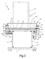
- base 2 ( figure 3 ) essentially consists of a box-type structure 10 elongated in the direction of the axis X, with constant section, having a flat horizontal bottom wall 11 and top wall 12, and a pair of vertical, reciprocally parallel side walls 13, 14.
- the side walls 13, 14 are reciprocally spaced at a distance smaller than the width of the walls 11, 12 so that the latter laterally protrude from the side walls 13, 14 with respective side wings 15.
- the sliding guides 3 of the first carriage 4 along the axis X are fixed under the side wings 15 of the top wall 12, which therefore presents a flat treadable upper surface 25, being also free from guides and delicate components, such as, for example, protection ribbons for the guides.
- the bottom of the wings 15 of the top wall 12 are machined so as to define respective resting surfaces 26 of the guides 3; for the rest, the wall 12, as well as all the walls 11, 13 and 14 may be relatively rough, thus considerably reducing the manufacturing costs of the base 2.
- the first carriage 4 comprises a lower base 16 mobile on the guides 3 and an upright 17 having a vertical axis tubular structure which extends upwards from the base 16 and carries the guides 5 of carriage 6.
- the base 16 consists of a central body 18 rigidly fastened to the upright 17 and a pair of side shoulders 19, 20 fixed to opposite sides of the central body 18 and each sliding along a respective guide.
- Each of the shoulders presents an essentially L-shaped section, with a vertical plate portion 22 adapted to be fastened to the central body 18 and a lower horizontal portion 23 extending underneath the respective wing 15.
- Ball circulation runners 24 cooperating with the respective guides 3 are fastened on portions 23, conveniently having I-section and provided with inclined surfaces defining an "O"-type contact pattern, in the example shown, with the balls.
- an "X"-type contact pattern may be used or the runners 24 may be of the pneumostatic type.
- shoulder 20 presents longer extension along the axis X and is provided with two runners 24; a single runner is carried by shoulder 19.
- guides 3 there are defined three rests in total, and therefore an isostatic constraint system by means of which carriage 4 is suspended from the guides 3.
- Such system is essentially rigid according to all degrees of freedom, except for translation along the axis X.
- the plate portions 22 of the shoulders 19, 20 are fastened to the central body by means of a plurality of screws 27.
- the mobile parts of the machine are moved, in a way per se known, by means of rack and pinion devices driven by respective electric motors 31, 32, 33.
- the first carriage 4 is actuated by an electric motor 31 carried by the shoulder 19 ( fig. 2 ), which provides motion via a belt 35 to a pulley 36 integral with a pinion 37 ( fig. 3 ) which meshes with a rack 38 fastened on the side wall 14 of the base 2 in a direction parallel to the axis X.
- the actuating devices of second carriage 6 and of arm 7 are similar and are not described in detail.
- connection of the electric motors 31, 32, 33 to the respective power and control system (not shown) is achieved by means of wirings (not shown) which are accommodated in articulated chains 40 in the transition zones between relatively moving parts.
- the top wall 12 of the base 2 is flat and defines a continuous, treadable upper surface 25. Since the guides 3 are arranged underneath the top wall 12, no particular protections are required and there is no risk of accumulation of dirt or presence of undesired bodies on the guides.
- the base itself is particularly simple and cost-effective to manufacture, in that the geometry of the top wall is simple and its surface finish, except for the resting surfaces 26, may be relatively rough.
- the measuring volume of the machine may be considerably expanded in the direction of axis X by joining several bases of the described type.
Landscapes
- Physics & Mathematics (AREA)
- General Physics & Mathematics (AREA)
- Nonlinear Science (AREA)
- A Measuring Device Byusing Mechanical Method (AREA)
- Length Measuring Devices With Unspecified Measuring Means (AREA)
Priority Applications (1)
| Application Number | Priority Date | Filing Date | Title |
|---|---|---|---|
| PL06745263T PL2010860T3 (pl) | 2006-04-06 | 2006-04-06 | Współrzędnościowa maszyna pomiarowa |
Applications Claiming Priority (1)
| Application Number | Priority Date | Filing Date | Title |
|---|---|---|---|
| PCT/IT2006/000231 WO2007113880A1 (en) | 2006-04-06 | 2006-04-06 | Coordinate measuring machine |
Publications (2)
| Publication Number | Publication Date |
|---|---|
| EP2010860A1 EP2010860A1 (en) | 2009-01-07 |
| EP2010860B1 true EP2010860B1 (en) | 2015-01-21 |
Family
ID=37055924
Family Applications (1)
| Application Number | Title | Priority Date | Filing Date |
|---|---|---|---|
| EP06745263.1A Expired - Lifetime EP2010860B1 (en) | 2006-04-06 | 2006-04-06 | Coordinate measuring machine |
Country Status (7)
| Country | Link |
|---|---|
| US (1) | US8091248B2 (pt) |
| EP (1) | EP2010860B1 (pt) |
| CN (1) | CN101460806B (pt) |
| BR (1) | BRPI0621566B8 (pt) |
| ES (1) | ES2531208T3 (pt) |
| PL (1) | PL2010860T3 (pt) |
| WO (1) | WO2007113880A1 (pt) |
Families Citing this family (5)
| Publication number | Priority date | Publication date | Assignee | Title |
|---|---|---|---|---|
| WO2007113879A1 (en) * | 2006-04-06 | 2007-10-11 | Hexagon Metrology S.P.A. | Horizontal-arm coordinate measuring machine |
| US8701298B2 (en) * | 2011-06-01 | 2014-04-22 | Tesa Sa | Coordinate measuring machine |
| WO2015153325A1 (en) * | 2014-04-04 | 2015-10-08 | Hexagon Metrology, Inc. | Coordinate measuring machine with carbon fiber air bearings |
| CN105364714A (zh) * | 2015-12-09 | 2016-03-02 | 苏州金逸康自动化设备有限公司 | 一种用于重型球形外壳打磨机的检测模组 |
| EP3222966B1 (en) * | 2016-03-23 | 2018-09-12 | Hexagon Technology Center GmbH | Coordinate measuring machine with an improved belt drive |
Family Cites Families (14)
| Publication number | Priority date | Publication date | Assignee | Title |
|---|---|---|---|---|
| CH608607A5 (pt) * | 1976-02-14 | 1979-01-15 | Bayerische Motoren Werke Ag | |
| US4630381A (en) * | 1984-07-24 | 1986-12-23 | Mitutoyo Mfg. Co., Ltd. | Coordinate measuring instrument |
| US4594794A (en) * | 1984-11-09 | 1986-06-17 | Exxon Research And Engineering Co. | Device for solids and fluid handling and distribution in a magnetically stabilized fluidized bed |
| US4594791A (en) | 1985-01-24 | 1986-06-17 | The Warner & Swasey Company | Bridge type coordinate measuring machine |
| IL81364A (en) * | 1987-01-23 | 1990-08-31 | Yaacov Sadeh | Electro optically corrected coordinate measuring machine |
| US4882847A (en) * | 1989-02-03 | 1989-11-28 | The Warner And Swasey Company | Coordinate measuring machine with improved carriage way arrangement |
| US5042162A (en) * | 1989-02-10 | 1991-08-27 | Brown & Sharpe Manufacturing Company | Coordinate measuring machine with vibration dampening system |
| CH686322A5 (de) * | 1990-04-25 | 1996-02-29 | Schneeberger Ag Maschf | Fuehrungsvorrichtung mit Messeinrichtung. |
| DE4026990A1 (de) | 1990-08-25 | 1992-02-27 | Stiefelmayer Kg C | Geradfuehrung zur fuehrung des schlittens eines vorzugsweise dreidimensionalen mess- und/oder anreissgeraetes |
| US5621978A (en) | 1993-07-14 | 1997-04-22 | Sarauer; Alan J. | Bar for coordinate measuring machine |
| DE19738099A1 (de) * | 1997-09-01 | 1999-03-04 | Zeiss Carl Fa | Koordinatenmeßgerät oder Bearbeitungsmaschine |
| JPH1130233A (ja) * | 1997-07-09 | 1999-02-02 | Thk Kk | 直線運動案内装置 |
| TW528881B (en) * | 2001-02-05 | 2003-04-21 | Hitachi Int Electric Inc | Position measuring apparatus |
| US7343684B2 (en) * | 2006-02-16 | 2008-03-18 | Brian Carlisle | Robotic system with traction drive |
-
2006
- 2006-04-06 PL PL06745263T patent/PL2010860T3/pl unknown
- 2006-04-06 CN CN2006800548734A patent/CN101460806B/zh not_active Expired - Lifetime
- 2006-04-06 US US12/296,071 patent/US8091248B2/en active Active
- 2006-04-06 WO PCT/IT2006/000231 patent/WO2007113880A1/en not_active Ceased
- 2006-04-06 BR BRPI0621566A patent/BRPI0621566B8/pt active IP Right Grant
- 2006-04-06 ES ES06745263T patent/ES2531208T3/es not_active Expired - Lifetime
- 2006-04-06 EP EP06745263.1A patent/EP2010860B1/en not_active Expired - Lifetime
Also Published As
| Publication number | Publication date |
|---|---|
| CN101460806B (zh) | 2012-05-23 |
| ES2531208T3 (es) | 2015-03-11 |
| WO2007113880A1 (en) | 2007-10-11 |
| US20090217540A1 (en) | 2009-09-03 |
| BRPI0621566B8 (pt) | 2019-03-19 |
| PL2010860T3 (pl) | 2015-06-30 |
| BRPI0621566A2 (pt) | 2011-12-13 |
| CN101460806A (zh) | 2009-06-17 |
| EP2010860A1 (en) | 2009-01-07 |
| US8091248B2 (en) | 2012-01-10 |
Similar Documents
| Publication | Publication Date | Title |
|---|---|---|
| US6976821B2 (en) | Device for the translatory positioning of a platform | |
| EP2200795B1 (en) | Device and method for processing slabs of stone or stone-like material | |
| EP1072353B1 (en) | Metal plate cutting machine | |
| CN1820951B (zh) | 液滴喷出装置及液滴喷头的维护方法 | |
| KR102134783B1 (ko) | 반송장치, 그것을 이용한 제조라인 및 제조라인의 변경방법 | |
| KR101496702B1 (ko) | 좌표 측정 기계 | |
| CN109643948A (zh) | 线性传送装置 | |
| ITMI942230A1 (it) | "maccina utensile per la lavorazione di pannelli e lastre. " | |
| WO2008139409A2 (en) | Loading/unloading system serving a sheet cutting centre, feeding tray therefor and relative handling method | |
| US11911860B2 (en) | Numerical-control machine tool | |
| KR20110027564A (ko) | 이동 재치 장치와 이동 재치 방법 | |
| EP3392610B1 (en) | Bearing mount | |
| KR102081538B1 (ko) | 원자로 헤드 검사 장치 | |
| US8091248B2 (en) | Coordinate measuring machine | |
| KR20000023016A (ko) | 2개의 스핀들 헤드를 구비한 공작 기계 | |
| EP2013569B1 (en) | Horizontal-arm coordinate measuring machine | |
| JP2587984Y2 (ja) | ワイヤ切断スパーク加工装置 | |
| CN218696008U (zh) | 一种双层滑台 | |
| CN104339174A (zh) | 加工机台 | |
| CN218937336U (zh) | 晶圆平面度测量装置 | |
| EP4032665A1 (en) | Telescoping linear extension robot | |
| US20240359363A1 (en) | Cantilevered cutting machine | |
| JPH02243258A (ja) | 門形平面研削盤 | |
| CN105666230A (zh) | 一种带双滑枕结构的搬运小车 | |
| EP2013568B1 (en) | Horizontal-arm coordinate measuring machine |
Legal Events
| Date | Code | Title | Description |
|---|---|---|---|
| PUAI | Public reference made under article 153(3) epc to a published international application that has entered the european phase |
Free format text: ORIGINAL CODE: 0009012 |
|
| 17P | Request for examination filed |
Effective date: 20081031 |
|
| AK | Designated contracting states |
Kind code of ref document: A1 Designated state(s): AT BE BG CH CY CZ DE DK EE ES FI FR GB GR HU IE IS IT LI LT LU LV MC NL PL PT RO SE SI SK TR |
|
| AX | Request for extension of the european patent |
Extension state: AL BA HR MK YU |
|
| 17Q | First examination report despatched |
Effective date: 20091109 |
|
| DAX | Request for extension of the european patent (deleted) | ||
| GRAP | Despatch of communication of intention to grant a patent |
Free format text: ORIGINAL CODE: EPIDOSNIGR1 |
|
| INTG | Intention to grant announced |
Effective date: 20140627 |
|
| GRAP | Despatch of communication of intention to grant a patent |
Free format text: ORIGINAL CODE: EPIDOSNIGR1 |
|
| INTG | Intention to grant announced |
Effective date: 20141121 |
|
| GRAS | Grant fee paid |
Free format text: ORIGINAL CODE: EPIDOSNIGR3 |
|
| GRAA | (expected) grant |
Free format text: ORIGINAL CODE: 0009210 |
|
| AK | Designated contracting states |
Kind code of ref document: B1 Designated state(s): AT BE BG CH CY CZ DE DK EE ES FI FR GB GR HU IE IS IT LI LT LU LV MC NL PL PT RO SE SI SK TR |
|
| REG | Reference to a national code |
Ref country code: GB Ref legal event code: FG4D |
|
| REG | Reference to a national code |
Ref country code: CH Ref legal event code: EP |
|
| REG | Reference to a national code |
Ref country code: IE Ref legal event code: FG4D |
|
| REG | Reference to a national code |
Ref country code: AT Ref legal event code: REF Ref document number: 707738 Country of ref document: AT Kind code of ref document: T Effective date: 20150215 |
|
| REG | Reference to a national code |
Ref country code: ES Ref legal event code: FG2A Ref document number: 2531208 Country of ref document: ES Kind code of ref document: T3 Effective date: 20150311 |
|
| REG | Reference to a national code |
Ref country code: DE Ref legal event code: R096 Ref document number: 602006044373 Country of ref document: DE Effective date: 20150312 |
|
| REG | Reference to a national code |
Ref country code: CH Ref legal event code: NV Representative=s name: KAMINSKI HARMANN PATENTANWAELTE AG, LI |
|
| REG | Reference to a national code |
Ref country code: NL Ref legal event code: VDEP Effective date: 20150121 |
|
| REG | Reference to a national code |
Ref country code: AT Ref legal event code: MK05 Ref document number: 707738 Country of ref document: AT Kind code of ref document: T Effective date: 20150121 |
|
| REG | Reference to a national code |
Ref country code: LT Ref legal event code: MG4D |
|
| REG | Reference to a national code |
Ref country code: PL Ref legal event code: T3 |
|
| PG25 | Lapsed in a contracting state [announced via postgrant information from national office to epo] |
Ref country code: SE Free format text: LAPSE BECAUSE OF FAILURE TO SUBMIT A TRANSLATION OF THE DESCRIPTION OR TO PAY THE FEE WITHIN THE PRESCRIBED TIME-LIMIT Effective date: 20150121 Ref country code: BG Free format text: LAPSE BECAUSE OF FAILURE TO SUBMIT A TRANSLATION OF THE DESCRIPTION OR TO PAY THE FEE WITHIN THE PRESCRIBED TIME-LIMIT Effective date: 20150421 Ref country code: LT Free format text: LAPSE BECAUSE OF FAILURE TO SUBMIT A TRANSLATION OF THE DESCRIPTION OR TO PAY THE FEE WITHIN THE PRESCRIBED TIME-LIMIT Effective date: 20150121 Ref country code: FI Free format text: LAPSE BECAUSE OF FAILURE TO SUBMIT A TRANSLATION OF THE DESCRIPTION OR TO PAY THE FEE WITHIN THE PRESCRIBED TIME-LIMIT Effective date: 20150121 |
|
| PG25 | Lapsed in a contracting state [announced via postgrant information from national office to epo] |
Ref country code: LV Free format text: LAPSE BECAUSE OF FAILURE TO SUBMIT A TRANSLATION OF THE DESCRIPTION OR TO PAY THE FEE WITHIN THE PRESCRIBED TIME-LIMIT Effective date: 20150121 Ref country code: GR Free format text: LAPSE BECAUSE OF FAILURE TO SUBMIT A TRANSLATION OF THE DESCRIPTION OR TO PAY THE FEE WITHIN THE PRESCRIBED TIME-LIMIT Effective date: 20150422 Ref country code: AT Free format text: LAPSE BECAUSE OF FAILURE TO SUBMIT A TRANSLATION OF THE DESCRIPTION OR TO PAY THE FEE WITHIN THE PRESCRIBED TIME-LIMIT Effective date: 20150121 Ref country code: NL Free format text: LAPSE BECAUSE OF FAILURE TO SUBMIT A TRANSLATION OF THE DESCRIPTION OR TO PAY THE FEE WITHIN THE PRESCRIBED TIME-LIMIT Effective date: 20150121 Ref country code: IS Free format text: LAPSE BECAUSE OF FAILURE TO SUBMIT A TRANSLATION OF THE DESCRIPTION OR TO PAY THE FEE WITHIN THE PRESCRIBED TIME-LIMIT Effective date: 20150521 |
|
| REG | Reference to a national code |
Ref country code: DE Ref legal event code: R097 Ref document number: 602006044373 Country of ref document: DE |
|
| PG25 | Lapsed in a contracting state [announced via postgrant information from national office to epo] |
Ref country code: EE Free format text: LAPSE BECAUSE OF FAILURE TO SUBMIT A TRANSLATION OF THE DESCRIPTION OR TO PAY THE FEE WITHIN THE PRESCRIBED TIME-LIMIT Effective date: 20150121 Ref country code: CZ Free format text: LAPSE BECAUSE OF FAILURE TO SUBMIT A TRANSLATION OF THE DESCRIPTION OR TO PAY THE FEE WITHIN THE PRESCRIBED TIME-LIMIT Effective date: 20150121 Ref country code: SK Free format text: LAPSE BECAUSE OF FAILURE TO SUBMIT A TRANSLATION OF THE DESCRIPTION OR TO PAY THE FEE WITHIN THE PRESCRIBED TIME-LIMIT Effective date: 20150121 Ref country code: DK Free format text: LAPSE BECAUSE OF FAILURE TO SUBMIT A TRANSLATION OF THE DESCRIPTION OR TO PAY THE FEE WITHIN THE PRESCRIBED TIME-LIMIT Effective date: 20150121 Ref country code: RO Free format text: LAPSE BECAUSE OF FAILURE TO SUBMIT A TRANSLATION OF THE DESCRIPTION OR TO PAY THE FEE WITHIN THE PRESCRIBED TIME-LIMIT Effective date: 20150121 |
|
| PLBE | No opposition filed within time limit |
Free format text: ORIGINAL CODE: 0009261 |
|
| STAA | Information on the status of an ep patent application or granted ep patent |
Free format text: STATUS: NO OPPOSITION FILED WITHIN TIME LIMIT |
|
| PG25 | Lapsed in a contracting state [announced via postgrant information from national office to epo] |
Ref country code: LU Free format text: LAPSE BECAUSE OF FAILURE TO SUBMIT A TRANSLATION OF THE DESCRIPTION OR TO PAY THE FEE WITHIN THE PRESCRIBED TIME-LIMIT Effective date: 20150406 Ref country code: MC Free format text: LAPSE BECAUSE OF FAILURE TO SUBMIT A TRANSLATION OF THE DESCRIPTION OR TO PAY THE FEE WITHIN THE PRESCRIBED TIME-LIMIT Effective date: 20150121 |
|
| 26N | No opposition filed |
Effective date: 20151022 |
|
| REG | Reference to a national code |
Ref country code: IE Ref legal event code: MM4A |
|
| PG25 | Lapsed in a contracting state [announced via postgrant information from national office to epo] |
Ref country code: SI Free format text: LAPSE BECAUSE OF FAILURE TO SUBMIT A TRANSLATION OF THE DESCRIPTION OR TO PAY THE FEE WITHIN THE PRESCRIBED TIME-LIMIT Effective date: 20150121 |
|
| REG | Reference to a national code |
Ref country code: FR Ref legal event code: PLFP Year of fee payment: 11 |
|
| PG25 | Lapsed in a contracting state [announced via postgrant information from national office to epo] |
Ref country code: IE Free format text: LAPSE BECAUSE OF NON-PAYMENT OF DUE FEES Effective date: 20150406 |
|
| PG25 | Lapsed in a contracting state [announced via postgrant information from national office to epo] |
Ref country code: BE Free format text: LAPSE BECAUSE OF FAILURE TO SUBMIT A TRANSLATION OF THE DESCRIPTION OR TO PAY THE FEE WITHIN THE PRESCRIBED TIME-LIMIT Effective date: 20150121 |
|
| REG | Reference to a national code |
Ref country code: FR Ref legal event code: PLFP Year of fee payment: 12 |
|
| PG25 | Lapsed in a contracting state [announced via postgrant information from national office to epo] |
Ref country code: HU Free format text: LAPSE BECAUSE OF FAILURE TO SUBMIT A TRANSLATION OF THE DESCRIPTION OR TO PAY THE FEE WITHIN THE PRESCRIBED TIME-LIMIT; INVALID AB INITIO Effective date: 20060406 |
|
| PG25 | Lapsed in a contracting state [announced via postgrant information from national office to epo] |
Ref country code: CY Free format text: LAPSE BECAUSE OF FAILURE TO SUBMIT A TRANSLATION OF THE DESCRIPTION OR TO PAY THE FEE WITHIN THE PRESCRIBED TIME-LIMIT Effective date: 20150121 |
|
| PG25 | Lapsed in a contracting state [announced via postgrant information from national office to epo] |
Ref country code: PT Free format text: LAPSE BECAUSE OF FAILURE TO SUBMIT A TRANSLATION OF THE DESCRIPTION OR TO PAY THE FEE WITHIN THE PRESCRIBED TIME-LIMIT Effective date: 20150521 |
|
| PG25 | Lapsed in a contracting state [announced via postgrant information from national office to epo] |
Ref country code: TR Free format text: LAPSE BECAUSE OF FAILURE TO SUBMIT A TRANSLATION OF THE DESCRIPTION OR TO PAY THE FEE WITHIN THE PRESCRIBED TIME-LIMIT Effective date: 20150121 |
|
| REG | Reference to a national code |
Ref country code: FR Ref legal event code: PLFP Year of fee payment: 13 |
|
| PGFP | Annual fee paid to national office [announced via postgrant information from national office to epo] |
Ref country code: PL Payment date: 20200316 Year of fee payment: 15 |
|
| PGFP | Annual fee paid to national office [announced via postgrant information from national office to epo] |
Ref country code: ES Payment date: 20200511 Year of fee payment: 15 Ref country code: CH Payment date: 20200424 Year of fee payment: 15 Ref country code: FR Payment date: 20200429 Year of fee payment: 15 |
|
| PGFP | Annual fee paid to national office [announced via postgrant information from national office to epo] |
Ref country code: GB Payment date: 20200429 Year of fee payment: 15 |
|
| GBPC | Gb: european patent ceased through non-payment of renewal fee |
Effective date: 20210406 |
|
| PG25 | Lapsed in a contracting state [announced via postgrant information from national office to epo] |
Ref country code: GB Free format text: LAPSE BECAUSE OF NON-PAYMENT OF DUE FEES Effective date: 20210406 Ref country code: FR Free format text: LAPSE BECAUSE OF NON-PAYMENT OF DUE FEES Effective date: 20210430 Ref country code: CH Free format text: LAPSE BECAUSE OF NON-PAYMENT OF DUE FEES Effective date: 20210430 Ref country code: LI Free format text: LAPSE BECAUSE OF NON-PAYMENT OF DUE FEES Effective date: 20210430 |
|
| REG | Reference to a national code |
Ref country code: ES Ref legal event code: FD2A Effective date: 20220630 |
|
| PG25 | Lapsed in a contracting state [announced via postgrant information from national office to epo] |
Ref country code: ES Free format text: LAPSE BECAUSE OF NON-PAYMENT OF DUE FEES Effective date: 20210407 |
|
| PG25 | Lapsed in a contracting state [announced via postgrant information from national office to epo] |
Ref country code: PL Free format text: LAPSE BECAUSE OF NON-PAYMENT OF DUE FEES Effective date: 20210406 |
|
| PGFP | Annual fee paid to national office [announced via postgrant information from national office to epo] |
Ref country code: DE Payment date: 20250428 Year of fee payment: 20 |
|
| PGFP | Annual fee paid to national office [announced via postgrant information from national office to epo] |
Ref country code: IT Payment date: 20250403 Year of fee payment: 20 |
|
| REG | Reference to a national code |
Ref country code: DE Ref legal event code: R071 Ref document number: 602006044373 Country of ref document: DE |