EP2011561A1 - Membranelement, membraneinheit und mehrstufige membraneinheit - Google Patents
Membranelement, membraneinheit und mehrstufige membraneinheit Download PDFInfo
- Publication number
- EP2011561A1 EP2011561A1 EP07708075A EP07708075A EP2011561A1 EP 2011561 A1 EP2011561 A1 EP 2011561A1 EP 07708075 A EP07708075 A EP 07708075A EP 07708075 A EP07708075 A EP 07708075A EP 2011561 A1 EP2011561 A1 EP 2011561A1
- Authority
- EP
- European Patent Office
- Prior art keywords
- membrane
- parts
- membrane elements
- spacer
- elements
- Prior art date
- Legal status (The legal status is an assumption and is not a legal conclusion. Google has not performed a legal analysis and makes no representation as to the accuracy of the status listed.)
- Withdrawn
Links
Images


Classifications
-
- B—PERFORMING OPERATIONS; TRANSPORTING
- B01—PHYSICAL OR CHEMICAL PROCESSES OR APPARATUS IN GENERAL
- B01D—SEPARATION
- B01D63/00—Apparatus in general for separation processes using semi-permeable membranes
- B01D63/08—Flat membrane modules
- B01D63/082—Flat membrane modules comprising a stack of flat membranes
- B01D63/0822—Plate-and-frame devices
-
- B—PERFORMING OPERATIONS; TRANSPORTING
- B01—PHYSICAL OR CHEMICAL PROCESSES OR APPARATUS IN GENERAL
- B01D—SEPARATION
- B01D65/00—Accessories or auxiliary operations, in general, for separation processes or apparatus using semi-permeable membranes
- B01D65/003—Membrane bonding or sealing
-
- C—CHEMISTRY; METALLURGY
- C02—TREATMENT OF WATER, WASTE WATER, SEWAGE, OR SLUDGE
- C02F—TREATMENT OF WATER, WASTE WATER, SEWAGE, OR SLUDGE
- C02F3/00—Biological treatment of water, waste water, or sewage
- C02F3/02—Aerobic processes
- C02F3/12—Activated sludge processes
- C02F3/1236—Particular type of activated sludge installations
- C02F3/1268—Membrane bioreactor systems
- C02F3/1273—Submerged membrane bioreactors
-
- B—PERFORMING OPERATIONS; TRANSPORTING
- B01—PHYSICAL OR CHEMICAL PROCESSES OR APPARATUS IN GENERAL
- B01D—SEPARATION
- B01D2313/00—Details relating to membrane modules or apparatus
- B01D2313/02—Specific tightening or locking mechanisms
-
- B—PERFORMING OPERATIONS; TRANSPORTING
- B01—PHYSICAL OR CHEMICAL PROCESSES OR APPARATUS IN GENERAL
- B01D—SEPARATION
- B01D2313/00—Details relating to membrane modules or apparatus
- B01D2313/06—External membrane module supporting or fixing means
-
- B—PERFORMING OPERATIONS; TRANSPORTING
- B01—PHYSICAL OR CHEMICAL PROCESSES OR APPARATUS IN GENERAL
- B01D—SEPARATION
- B01D2313/00—Details relating to membrane modules or apparatus
- B01D2313/12—Specific discharge elements
-
- B—PERFORMING OPERATIONS; TRANSPORTING
- B01—PHYSICAL OR CHEMICAL PROCESSES OR APPARATUS IN GENERAL
- B01D—SEPARATION
- B01D2313/00—Details relating to membrane modules or apparatus
- B01D2313/14—Specific spacers
-
- B—PERFORMING OPERATIONS; TRANSPORTING
- B01—PHYSICAL OR CHEMICAL PROCESSES OR APPARATUS IN GENERAL
- B01D—SEPARATION
- B01D2313/00—Details relating to membrane modules or apparatus
- B01D2313/26—Specific gas distributors or gas intakes
-
- B—PERFORMING OPERATIONS; TRANSPORTING
- B01—PHYSICAL OR CHEMICAL PROCESSES OR APPARATUS IN GENERAL
- B01D—SEPARATION
- B01D2315/00—Details relating to the membrane module operation
- B01D2315/06—Submerged-type; Immersion type
-
- Y—GENERAL TAGGING OF NEW TECHNOLOGICAL DEVELOPMENTS; GENERAL TAGGING OF CROSS-SECTIONAL TECHNOLOGIES SPANNING OVER SEVERAL SECTIONS OF THE IPC; TECHNICAL SUBJECTS COVERED BY FORMER USPC CROSS-REFERENCE ART COLLECTIONS [XRACs] AND DIGESTS
- Y02—TECHNOLOGIES OR APPLICATIONS FOR MITIGATION OR ADAPTATION AGAINST CLIMATE CHANGE
- Y02W—CLIMATE CHANGE MITIGATION TECHNOLOGIES RELATED TO WASTEWATER TREATMENT OR WASTE MANAGEMENT
- Y02W10/00—Technologies for wastewater treatment
- Y02W10/10—Biological treatment of water, waste water, or sewage
Definitions
- the invention relates to a membrane unit and a membrane element suitable to be used as a membrane filtration apparatus particularly for wastewater treatment and water purification treatment.
- a membrane separation technique to be applied for wastewater treatment has been known a technique of obtaining membrane-filtered water by immersing a membrane unit in which a plurality of membrane elements are arranged and inserted in a treatment tank filled with wastewater such as activated sludge and by suctioning the filtered water side of the membrane unit by a pump, or discharging water based on the water level difference just like a siphon.
- the method of increasing an air amount is a preferable for removing contaminations of the filtering membrane surface because of a strenuous pulsation.
- an excess load is applied to the supporting plate of the membrane element, the displacement of the membrane elements tends to occur.
- the supporting plate bends considerably and tends to deform, the spacer parts move slightly, and thus a problem of causing wear tends to occur.
- the membrane unit apparatus in which intervals of the raw water channels are kept constant by bringing the above-mentioned spacer parts into contact with each other, there is a problem that the intervals of the raw water channels of membrane faces are easily fluctuated due to vibration of the membrane elements generated during the operation.
- a membrane unit is assembled by arranging a plurality of membrane elements having spacer parts in both right and left sides of supporting plates in such a manner that the spacer parts are brought into contact with each other and uniting the membrane elements by inserting through bolts into holes formed in the supporting plates (see Patent Document 4).
- the through bolts 45 have to be fastened to make the fastening force of the contacting spacer parts higher than the force applied to the supporting plates, and then the slight movement of the spacer parts can be prevented.
- An object of the invention is to solve the above-mentioned problems and provide a membrane element, a membrane unit, and a multi-deck membrane unit with which a space part surrounded with a frame body can easily be installed above the membrane element regardless of a number of the membrane element and wear of spacer parts can be suppressed.
- Another object of the invention is to provide a membrane element, a membrane unit, and a multi-deck membrane unit with which air supplied from the lower part of the membrane element can efficiently be utilized and the efficiency in terms of an apparatus production can be improved.
- the invention includes the following configuration. That is:
- phrases such as “both side parts”, “upper end part”, “above”, “side face”, “outermost part” and the like are determined on the basis of the state at the time of use.
- a plurality of the membrane elements of the invention can be arranged in such a manner that the distances of raw water channels to be formed between the respective membrane elements are kept constant by bringing the spacer parts into contact with one another; and further, a membrane unit without requiring an additional housing and a frame body surrounding the space above the filtering membranes can be formed by bringing the seal panels into contact with one another. According to the invention, regardless of the number of the membrane elements and the size of the membrane units, a space can reliably be kept above the membrane elements.
- the membrane unit can be easily layered in multi-decks and it is advantageous in terms of the cost, and the space shape between upper and lower decks is always kept constant and controlled gas-liquid mixing flow can be efficiently utilized.
- the vibration of spacer parts due to pulsation is suppressed and wear is decreased by inserting through bolts into the through bolt insertion holes of the spacer parts and fastening a plurality of the membrane elements. In this case, the through bolts do not interrupt the gas-liquid mixing flow.
- the membrane unit is configured by arranging a plurality of the membrane elements while bringing the channel parts into contact with one another and also bringing the seal panels into contact with one another, so that the water collecting pipe for taking filtered water out can be formed in the upper part of the membrane unit.
- a tube for taking out filtered water is not necessary and thus the membrane unit can be easily multi-layered without particular work (e.g. formation of through holes for leading a tube to the outside of a module) of the wall parts forming the space parts above the membrane elements.
- Fig. 1 is a schematic perspective view showing one embodiment of a membrane element of the invention and showing the state before filtering membranes 11 are attached to the supporting plate 12.
- Fig. 2 is a schematic perspective view showing one embodiment of a membrane module 41 produced by combining a membrane unit 42 using the membrane element 1 with an air diffuser.
- Fig. 3 is a schematic top view showing the top face of the membrane unit 41.
- the membrane element 1 shown in Fig. 1 is configured by installing the filtering membranes 11 on both surfaces of the plate-like supporting plate 12, and spacer parts 13 for keeping the prescribed distance to an adjacent membrane element are formed in both right and left sides (end parts in the horizontal direction of the membrane elements) of the supporting plate 12.
- the spacer parts 13 are thicker than the supporting plate and are extended upward higher than the upper end part of the supporting plate (the upward extended parts are called as extended parts 15).
- a nozzle-like filtered water outlet 17 is at the upper end part of the supporting plate 12.
- sheet-like filtering membranes 11 are installed on both front and rear surfaces of the supporting plate 12, and a filtered water flowing space (filtered water chamber) is formed in the inside of the filtering membranes.
- the filtered water outlet 17 is connected to the filtered water chamber between the filtering membranes 11 and the supporting plate 12 via a channel 18. The filtered water flowing into the filtered water chamber after filtered from the outside of the filtering membranes 11 is discharged out of the filtered water outlet 17 via the channel 18.
- the supporting plate 12 is not particularly limited as long as it is an approximately flat plate-like one.
- a material for that is not particularly limited as long as it is a material having toughness equivalent to a bending elastic modulus of about 300 MPa according to ASTM testing method D790 (2003); however, metals such as stainless steels, resins such as acrylonitrile-butadiene-styrene rubber (ABS resin) and vinyl chloride, composite materials such as fiber-reinforced resin (FRP), and other materials may be properly selected and used.
- the spacer parts 13 are thick parts installed at both side parts of the supporting plate 12, and as shown in Fig. 3 , raw water channels 51 are formed between filtering membranes of the adjacent membrane elements 1 by these spacer parts 13. Therefore, the thickness of the spacer parts 13 is set in accordance with the width of the raw water channels 51.
- the width of the raw water channels 51 is not particularly limited; however, it is preferably set to adjust the flow speed of the raw water flowing in the raw water channels 51 to be 0.1 to 1.5 m/s.
- the shape of the through bolt insertion holes 14 being formed in the spacer parts 13 is not particularly limited and may be determined corresponding to the fastening force required for the spacer parts. However, as shown in Fig. 1 , if they are made to be U-shape holes opened to the side face of the membrane elements and penetrating form the front surface to the rear surfaces of the membrane elements, through bolts 46 can be inserted into the layered membrane elements from the sides and thus the work is made easy and accordingly, it is preferable. Further, it is preferable that the depth of the U-shape is equal to or more than the diameter of the through bolts 46 and the through bolts 46 be entirely put in the U-shape holes. The depth of the U-shape is a length in the horizontal direction and in the plane direction of the membrane elements and is the length between the most projected point and the most recessed point in the spacer parts, and it is shown as L1 in Fig. 1 .
- the number and the size of the through bolt insertion holes 14 may be also determined depending on the fastening force required for the spacer parts.
- the fastening force required for the spacer parts is, for example, a stress of 1 kg/cm 2 (9.807 ⁇ 10 4 Pa) or higher, and it is preferable to determine it together with the specification of the through bolts 46 so as to give the fastening stress.
- through bolts 46 of M12 to M16 made of SUS 304
- the width of the spacer parts 13 is even in the longitudinal direction (vertical direction at the time of use) of the membrane elements; however a form in which the width is made uneven is also preferably usable.
- the width of the spacer parts means the length of the portion excluding the through bolt insertion holes 14 in the horizontal direction and in the membrane element plane direction.
- ribs 23 intermittently at the outside parts of the spacer parts 13 as shown in the membrane element 1 shown in Fig. 4 and to form the through bolt insertion holes 14 in the ribs 23.
- the ribs 23 may be produced integrally from the same material as that of other portions of the spacer parts 13. According to such a configuration, the fastening force can be maintained by inserting through bolts with a desired diameter and the area of the spacer parts can be narrowed, and thus the spacer parts can be evenly fastened to one another.
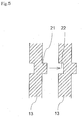
- projection parts 21 for fitting and reception parts 22 for fitting it in the spacer parts 13 are also preferable to form projection parts 21 for fitting and reception parts 22 for fitting it in the spacer parts 13 as shown in the cross-sectional view of Fig. 5 so as to easily position at the time of arranging a plurality of membrane elements.
- the positioning of the through bolt insertion holes 14 is thus made easy and through bolts 46 can be easily inserted into a plurality of layered membrane elements.
- the extended parts 15 may have a structure formed simply by extending the spacer parts 13 upward higher than the upper end parts of the membrane elements 1 as shown in Fig. 1 or may be formed to have a shape different from other portions of the spacer parts 13 as shown in Fig. 6 .
- the channel parts 31 are formed in the extended parts 15 corresponding to the upper parts of the spacer parts 13.
- the channel parts 31 have through holes 32 for forming water collecting pipes of filtered water in the approximately center in the thickness direction (in the arrangement direction of the membrane elements at the time of use) and are configured in such a manner that filtered water can flow from the filtered water chambers to the through holes 32 for forming a water collecting pipe via collecting grooves 16 and channels 18 formed at the supporting plates 12.
- the through holes 32 for forming the water collecting pipe form a continuous water collecting pipe when a membrane unit is assembled by arranging the membrane elements in such a manner that the channel parts thereof are brought into contact with one another as shown in Fig. 7 .
- the entire circumferential rim parts of the filtering membrane 11 are liquid-tightly fixed to the supporting plates 12 by means such as melt deposition, fusion, adhesion, or the like to partition the filtering membranes 11 in which the outer face is raw water side and the inner face is filtered water side.
- the filtering membranes 11 are not particularly limited, in the case of solid-liquid separation of activated-sludge water, a flat membrane type filtering membrane with a pore diameter determining the filtration capability of the filtering membranes 11 in a range of 0.01 to 20 ⁇ m is preferable.
- Fig. 2 is a schematic perspective view showing one embodiment of a membrane module produced by combining a membrane unit using the membrane element shown in Fig. 1 with an air diffuser
- Fig. 3 is a schematic top view thereof
- Fig. 7 is a schematic perspective view showing one embodiment of a membrane module produced by combining a membrane unit using the membrane elements shown in Fig. 6 with an air diffuser
- Fig. 8 is a schematic drawing showing an integration method of the membrane elements 1 and the seal panels 45.
- the membrane units 42 of the invention shown Figs. 2 and 7 are basically composed of a plurality of the membrane elements 1 as described above and the seal panels 45 installed to the outermost parts of these membrane elements 1, and through bolts 46 are optionally employed for integration.
- the outermost parts of a plurality of the membrane elements 1 mean both end parts in the membrane element arrangement direction.
- the seal panels 45 are plate-like ones for covering the outermost parts of the arranged membrane elements 1, and in the case of integration by through bolts, through bolt insertion holes 52 are formed. Since the respective raw water channels 51 between membrane elements 1 are preferable to have approximately uniform width, it is preferable to install spacer parts to the both right and left side parts (the side brought into contact with the spacer parts 13 of the membrane elements) of the inner side faces of the seal panels 45 so as to form the raw water channels 51 with approximately same width between the membrane elements as shown in Fig. 3 also.
- a material for the seal panel 45 is not particularly limited and same materials as those of the supporting plates 12 can be properly selected.
- the through bolts 46 are not particularly limited as long as they can integrate and fix the seal panels 45 and a plurality of membrane elements 1 by penetration.
- the number of the through bolts and the bolt diameter may be properly set depending on the fastening force and weight of the membrane unit 42. At the time of fixation of the through bolts 46, it is preferable to fix them by setting nuts 50 at both ends.
- the membrane elements are arranged, and in this case, the extended parts 15 are brought into contact with one another. Accordingly, the extended parts 15 of the spacer parts 13 form walls at the upper and two opposed side faces of the membrane unit. Further, the seal panels 45 are layered at the outermost parts of the membrane elements 1, and walls are formed at remaining two opposed side faces of the membrane unit by the upper parts of the seal panels 45 by using those having a shape covering the extended parts 15 for the seal panels 45.
- a frame body 48 surrounding the space above the filtering membranes is formed by the extended parts 15 and the seal panels 45, and by the frame body 48, a space part 49 above the membrane elements 1 can be reliably retained. Accordingly, the speed of the gas-liquid mixing flow can be increased without installing upper housing, being an additional part, above the membrane elements.
- the membrane elements 1 and the seal panels 45 are united by the through bolts 46.
- through bolts 46 are fitted into the through bolt insertion holes 14 of a plurality of the arranged membrane elements 1 from the side and then inserted into hole parts 52 of one seal panel 45. Thereafter, the membrane elements are moved to bring the spacer parts into contact with one another. After a prescribed number of membrane elements are arranged, the through bolts 46 are inserted into hole parts 52 of the other seal panel 45 and fixed by nuts 50. In such a manner, the membrane unit 42 can be assembled.
- the assembly space necessary for inserting the through bolts 46 into a plurality of the membrane elements 1 can be narrowed as compared with that in the case where the holes have a simple hole shape not opened to the side face, and further the through bolts 46 can be easily inserted.
- the holes to be formed in the seal panels 45 are made simple circular holes not opened to the side, so that the through bolts 46 can be prevented from dropping by tremors during the operation.
- the through bolts 46 are fitted in the U-shape parts from the side, and thereafter, the through bolts 46 may be inserted into the hole parts 52 of the seal panels 45 to unit the membrane elements simultaneously with installation of them. Further, while one seal panel 45 is laid on a floor face, a plurality of membrane elements 1 are layered thereon and the through bolts 46 are fitted in the U-shape parts 14 and the hole parts 52 from the side, and the other seal panel 45 is finally layered on the uppermost membrane element 1 to unit them (not shown). In any case, the through bolts 46 can be inserted into the U-shape part 14 from a narrow space in the side of the membrane elements.
- the channel parts 31 having through holes 32 for forming a water collecting pipe are brought into contact with one another to communicate the through holes 32 and form the water collecting pipe, and the water collecting pipe is provided with a function as a water collecting conduit for collecting the filtered water coming out of a plurality of the membrane elements 1.
- the adjacent channel parts 31 may be stuck and sealed; however it is more preferable to insert O-rings, gaskets, liquid-type gaskets or the like between the respectively channel parts 31 and to fasten and seal them with through bolts 46.
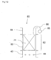
- water collecting caps 53 for taking collected filtered water out are preferably installed at positions corresponding to the channel parts 31 in the both outmost parts of a plurality of membrane elements 1. Accordingly, collecting pipes 85 and tubes 86, as shown in Fig. 12 , which are required for prior arts are no more needed, and installation of the membrane module 41 can be advantageously carried out in a space saving manner. Further, at the time of operation, due to the air discharged from the air diffuser 44, upward gas-liquid mixing flow is generated in the membrane module and on the other hand, downward flow of wastewater is generated in the outside of the membrane module. In the case of the configuration as shown in Fig. 7 , since inhibition of the upward flow by a tube or inhibition of the downward flow by a collecting pipe does not occur, even flow in right and left can be advantageously generated without decreasing the speed of the gas-liquid mixing flow,.
- the membrane unit 42 assembled in such a manner is used as a membrane module 41 by installing the air diffuser 44 for jetting air under the unit.
- the air diffuser 44 may be fixed in a stand 43 mounting the membrane unit 42 thereon as shown in Fig. 2 and Fig. 7 , or may be installed separately.
- the installation and configuration of the diffuser 44 are not also particularly limited; the installation may be proper to evenly send air to a plurality of the membrane elements and the configuration may be proper to have air diffusion holes.
- a plurality of pipes are installed under the membrane elements 1 and air diffusion holes are formed at constant intervals in the upper faces or lower faces of the pipes.
- the number and the size of the holes as the air diffusion holes are not particularly limited and may be properly set depending on the air amount.
- a lower frame body 47 under the membrane unit 42 between the stand 43 and the membrane unit. Installation stability of the membrane unit 42 can be increased by mounting the membrane unit 42 on the lower frame body 47 and then on the stand 43. That is, in the case where the lower frame body 47 is installed, when the membrane unit 42 is hung up, a problem that the arranged membrane elements are displaces or the through bolts 46 are loosened can be solved.
- the lower frame body 47 is preferable to have a structure to be fixed by bolts under the seal panels 45. Further, the lower frame body 47 is preferable to have a shape having an open space just under the membrane elements not so as to inhibit the raw water channel 51.
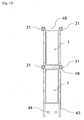
- a plurality of the membrane units of the invention may be layered vertically in multi-decks.
- the space part 49 surrounded with the frame body 48 composed of the extended parts 15 of the spacer parts 13 and the seal panels 45 is formed on the upper part of each membrane unit 42. That is, as shown in Fig. 10 (cross-sectional view of Fig. 9 ), without installation of a conventionally used upper housing 84 (see Fig. 13 ), the space part 49 can be formed between an upper and a lower membrane units.
- a conventional module 81 of multi-deck membrane units as shown in Fig.
- the module since the module has a configuration that the filtered water flowing out of the lower-deck membrane unit 82 is collected to a collecting pipe 85 via a tube 86, a drilling work for opening a hole for passing the tube 86 to the upper housing 84 is necessary; however, in the case of the multi-deck membrane unit structure using the membrane elements 1 as shown in Fig. 6 , such a drilling work is not required and the installation space for the collecting pipes 85 and 85' (see Fig. 13 ) is also no more needed, so that the treatment tank can be advantageously made compact.
- another housing (not shown) may be installed between the lower-deck membrane unit and the upper-deck membrane unit. Even in the case of installing another housing, the upper housing can be made to have a lower height than that of a conventional one.
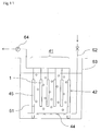
- the membrane module 41 is used while being immersed in a treatment tank 63 storing water 61 to be treated.
- the membrane module 41 is immersed in the treatment tank 63 storing the water 61 to be treated, a suction pump 64 for suctioning the filtered water is connected to the membrane module 41, and a pipe 62 for supplying air is connected to the air diffuser 44.
- the suction pump 64 is used for taking the filtered water out of membrane unit 42; however, additionally, gravity filtration may be carried out using head difference between the water surface in the treatment tank 63 and the part where filtered water is taken out.
- the water 61 to be treated such as wastewater is passed through the filtering membranes installed in the membrane elements 1 by suctioning force of the pump.
- microorganism particles and suspended solid such as inorganic particles or the like contained in the water 61 to be treated can be filtered and remain in the water 61 side.
- the water passing through the filtering membranes (filtered water) is taken outside of the treatment tank 63 from the spaces (filtered water chambers) between the supporting plates and filtering membranes via the water collecting pipes and the like.
- air is jetting from the air diffuser 44 and enters to the raw water channels of the membrane units.
- the ascending gas-liquid mixing flow parallel to the membrane faces of the membrane elements 1 generated by ascending air separates the filtered matter deposited on the membrane faces and washes the membrane faces.
- the membrane elements and membrane units of the invention can be used in the case of water filtration treatment while being installed in a treatment tank and can be utilized for wastewater treatment and water purification treatment.
Landscapes
- Chemical & Material Sciences (AREA)
- Life Sciences & Earth Sciences (AREA)
- Chemical Kinetics & Catalysis (AREA)
- Biodiversity & Conservation Biology (AREA)
- Microbiology (AREA)
- Hydrology & Water Resources (AREA)
- Engineering & Computer Science (AREA)
- Environmental & Geological Engineering (AREA)
- Water Supply & Treatment (AREA)
- Organic Chemistry (AREA)
- Separation Using Semi-Permeable Membranes (AREA)
- Packages (AREA)
Applications Claiming Priority (4)
| Application Number | Priority Date | Filing Date | Title |
|---|---|---|---|
| JP2006085201 | 2006-03-27 | ||
| JP2006117580 | 2006-04-21 | ||
| JP2006117581 | 2006-04-21 | ||
| PCT/JP2007/051957 WO2007122839A1 (ja) | 2006-03-27 | 2007-02-06 | 膜エレメント、膜ユニット及び多段積み膜ユニット |
Publications (2)
| Publication Number | Publication Date |
|---|---|
| EP2011561A1 true EP2011561A1 (de) | 2009-01-07 |
| EP2011561A4 EP2011561A4 (de) | 2011-05-25 |
Family
ID=38624757
Family Applications (1)
| Application Number | Title | Priority Date | Filing Date |
|---|---|---|---|
| EP07708075A Withdrawn EP2011561A4 (de) | 2006-03-27 | 2007-02-06 | Membranelement, membraneinheit und mehrstufige membraneinheit |
Country Status (8)
| Country | Link |
|---|---|
| US (1) | US20100000935A1 (de) |
| EP (1) | EP2011561A4 (de) |
| JP (1) | JPWO2007122839A1 (de) |
| KR (1) | KR20080110862A (de) |
| AU (1) | AU2007242360B2 (de) |
| CA (1) | CA2647654A1 (de) |
| TW (1) | TW200740515A (de) |
| WO (1) | WO2007122839A1 (de) |
Cited By (7)
| Publication number | Priority date | Publication date | Assignee | Title |
|---|---|---|---|---|
| EP2239234A1 (de) * | 2009-03-09 | 2010-10-13 | Shenzen JDL Environmental Protection Ltd. | Strahlbelüftungsvorrichtung und Abwasserbehandlungsverfahren |
| EP2322268A1 (de) * | 2009-11-03 | 2011-05-18 | LG Electronics Inc. | Membrantrennvorrichtung des Immersionstyps |
| EP2236196A3 (de) * | 2009-03-31 | 2012-08-08 | Hitachi Plant Technologies, Ltd. | Membranpatrone in Membrantrennvorrichtung des Immersionstyps |
| EP2223736A4 (de) * | 2007-12-13 | 2012-08-22 | Kubota Kk | Tauchmembranabscheider |
| EP2228124A4 (de) * | 2007-11-28 | 2012-08-22 | Kubota Kk | Tauch-filmkassettentrennvorrichtung und filmkassette |
| WO2014084057A1 (ja) * | 2012-11-27 | 2014-06-05 | 東レ株式会社 | 分離膜モジュール |
| EP2591846B1 (de) * | 2011-11-10 | 2023-06-07 | Pall Corporation | Flüssigkeitsbehandlungsanordnungen |
Families Citing this family (18)
| Publication number | Priority date | Publication date | Assignee | Title |
|---|---|---|---|---|
| DE102008012305A1 (de) | 2008-03-03 | 2009-09-17 | Microdyn - Nadir Gmbh | Filtrationsvorrichtung für Mikro-, Ultra- und Nanofiltration |
| JP5474482B2 (ja) * | 2009-10-09 | 2014-04-16 | 旭化成ケミカルズ株式会社 | 膜浸漬槽及び膜処理装置 |
| EP2550085B1 (de) * | 2010-03-24 | 2018-05-09 | Bionest Technologies Inc. | Membranfiltersystem |
| JP5583036B2 (ja) * | 2011-01-18 | 2014-09-03 | 株式会社クボタ | 膜分離装置 |
| US20130221546A1 (en) * | 2012-02-29 | 2013-08-29 | Veolia Water Solutions & Technologies Support | Flat Sheet Membrane Module |
| JP6164216B2 (ja) * | 2012-07-10 | 2017-07-19 | 東レ株式会社 | エレメントユニット、分離膜モジュール、分離膜エレメントの着脱方法 |
| EP2897715B1 (de) * | 2012-09-21 | 2016-09-14 | WTA Vogtland GmbH | Stapel von an den ecken eingekapselten membranfiltertaschen |
| KR101364362B1 (ko) | 2012-12-28 | 2014-02-19 | 코오롱인더스트리 주식회사 | 여과장치 |
| JP6089854B2 (ja) * | 2013-03-26 | 2017-03-08 | 株式会社明電舎 | 膜ユニット及び膜ユニット複合体 |
| US10335740B2 (en) * | 2013-12-11 | 2019-07-02 | Kolon Industries, Inc. | Submerged-type filtration apparatus |
| RU2708861C2 (ru) * | 2015-03-24 | 2019-12-11 | Арстрома Ко., Лтд. | Устройство разделения текучих сред, включающее мембрану для разделения текучих сред, и мембранный модуль для разделения текучих сред |
| KR102020787B1 (ko) * | 2015-09-02 | 2019-09-11 | 주식회사 아모그린텍 | 수처리용 평판형 필터 및 이를 이용한 수처리용 필터모듈 |
| JP6624984B2 (ja) * | 2016-03-22 | 2019-12-25 | 株式会社クボタ | 膜分離装置、延長用膜ケース、膜分離装置セットおよび膜エレメントの入れ替え方法 |
| KR102394715B1 (ko) | 2018-12-11 | 2022-05-06 | 주식회사 아모그린텍 | 중력식 정수장치용 필터모듈 및 이를 포함하는 중력식 정수장치 |
| KR20210132921A (ko) * | 2020-04-28 | 2021-11-05 | 주식회사 아모그린텍 | 중력식 정수장치용 필터모듈 및 이를 포함하는 중력식 정수장치 |
| KR20220034591A (ko) * | 2020-09-11 | 2022-03-18 | 주식회사 아모그린텍 | Mbr 시스템 |
| CN115155316B (zh) * | 2022-08-18 | 2023-07-28 | 淄博瀚泓环保科技有限公司 | 一种中央楼宇酸化水的水处理方法 |
| JP2024061485A (ja) * | 2022-10-21 | 2024-05-07 | 株式会社エフ・シー・シー | 濾過膜ユニット |
Family Cites Families (23)
| Publication number | Priority date | Publication date | Assignee | Title |
|---|---|---|---|---|
| US2453613A (en) * | 1945-04-26 | 1948-11-09 | Electric Steel Foundry | Sanitary filter |
| US2512365A (en) * | 1947-09-26 | 1950-06-20 | Muller Juan | Filter for the clarification of oils |
| GB1132164A (en) * | 1965-12-10 | 1968-10-30 | Kimura Entetsu Kagaku Kikai Co | A method for recovering an electrolyte from a highly viscous solution by dialysis, and apparatus therefor |
| USRE30632E (en) * | 1971-02-25 | 1981-06-02 | Rhone Poulenc, S.A. | Separation apparatus |
| FR2236538B1 (de) * | 1973-07-11 | 1976-05-07 | Rhone Poulenc Ind | |
| DE3914592C2 (de) * | 1988-05-13 | 1997-04-30 | Sartorius Gmbh | Verfahren und Filtermodul zur Filtration von Flüssigkeiten im Cross-Flow-Betrieb |
| DK0510328T3 (da) * | 1991-03-07 | 1996-02-05 | Kubota Kk | Apparat til behandling af aktiveret slam |
| JPH0660427U (ja) | 1993-01-28 | 1994-08-23 | 株式会社クボタ | 膜モジュール |
| JPH0796150A (ja) * | 1993-09-28 | 1995-04-11 | Kurita Water Ind Ltd | 膜分離装置の平膜ユニット |
| TW255835B (en) * | 1994-01-07 | 1995-09-01 | Kubota Kk | Filtration membrane module |
| JPH07299339A (ja) * | 1994-05-09 | 1995-11-14 | Kubota Corp | 平板型膜分離装置 |
| US5451317A (en) * | 1994-09-08 | 1995-09-19 | Kubota Corporation | Solid-liquid separator |
| JPH0889766A (ja) * | 1994-09-26 | 1996-04-09 | Nitto Denko Corp | 膜分離装置 |
| JPH0889765A (ja) | 1994-09-26 | 1996-04-09 | Nitto Denko Corp | 膜分離装置 |
| JPH09122458A (ja) * | 1995-10-30 | 1997-05-13 | Nitto Denko Corp | 膜モジュ−ル用エレメント |
| JP3290577B2 (ja) | 1995-11-21 | 2002-06-10 | 株式会社クボタ | 浸漬型膜分離装置 |
| JPH11226364A (ja) * | 1998-02-20 | 1999-08-24 | Hitachi Zosen Corp | 膜分離装置 |
| JP3667131B2 (ja) | 1998-12-28 | 2005-07-06 | 株式会社クボタ | 浸漬型膜分離装置 |
| JP2001104759A (ja) * | 1999-10-06 | 2001-04-17 | Mitsubishi Heavy Ind Ltd | 濾過膜カートリッジ、及びこれを用いた濾過膜モジュール |
| JP3867481B2 (ja) * | 2000-06-29 | 2007-01-10 | 株式会社日立プラントテクノロジー | 浸漬平膜分離装置 |
| JP2004121943A (ja) * | 2002-09-30 | 2004-04-22 | Yuasa Corp | 膜エレメントおよびこれを用いた膜ユニット |
| EP1466658A1 (de) * | 2003-04-11 | 2004-10-13 | UTISOL Technologies AG | Belüftungsvorrichtung und Belüftungsverfahren für Membranfilter |
| US8177974B2 (en) * | 2006-04-14 | 2012-05-15 | Emd Millipore Corporation | Disposable tangential flow filtration device holder |
-
2007
- 2007-02-06 KR KR1020087026039A patent/KR20080110862A/ko not_active Withdrawn
- 2007-02-06 AU AU2007242360A patent/AU2007242360B2/en not_active Ceased
- 2007-02-06 US US12/294,586 patent/US20100000935A1/en not_active Abandoned
- 2007-02-06 WO PCT/JP2007/051957 patent/WO2007122839A1/ja not_active Ceased
- 2007-02-06 EP EP07708075A patent/EP2011561A4/de not_active Withdrawn
- 2007-02-06 JP JP2007524693A patent/JPWO2007122839A1/ja not_active Withdrawn
- 2007-02-06 CA CA002647654A patent/CA2647654A1/en not_active Abandoned
- 2007-02-27 TW TW096106832A patent/TW200740515A/zh unknown
Cited By (9)
| Publication number | Priority date | Publication date | Assignee | Title |
|---|---|---|---|---|
| EP2228124A4 (de) * | 2007-11-28 | 2012-08-22 | Kubota Kk | Tauch-filmkassettentrennvorrichtung und filmkassette |
| US9878290B2 (en) | 2007-11-28 | 2018-01-30 | Kubota Corporation | Submerged membrane separator and membrane cartridge |
| EP2223736A4 (de) * | 2007-12-13 | 2012-08-22 | Kubota Kk | Tauchmembranabscheider |
| EP2239234A1 (de) * | 2009-03-09 | 2010-10-13 | Shenzen JDL Environmental Protection Ltd. | Strahlbelüftungsvorrichtung und Abwasserbehandlungsverfahren |
| EP2236196A3 (de) * | 2009-03-31 | 2012-08-08 | Hitachi Plant Technologies, Ltd. | Membranpatrone in Membrantrennvorrichtung des Immersionstyps |
| AU2010201007B2 (en) * | 2009-03-31 | 2013-11-28 | Hitachi, Ltd. | Membrane cartridge in immersion type membrane separation apparatus |
| EP2322268A1 (de) * | 2009-11-03 | 2011-05-18 | LG Electronics Inc. | Membrantrennvorrichtung des Immersionstyps |
| EP2591846B1 (de) * | 2011-11-10 | 2023-06-07 | Pall Corporation | Flüssigkeitsbehandlungsanordnungen |
| WO2014084057A1 (ja) * | 2012-11-27 | 2014-06-05 | 東レ株式会社 | 分離膜モジュール |
Also Published As
| Publication number | Publication date |
|---|---|
| TW200740515A (en) | 2007-11-01 |
| WO2007122839A1 (ja) | 2007-11-01 |
| AU2007242360A1 (en) | 2007-11-01 |
| CA2647654A1 (en) | 2007-11-01 |
| JPWO2007122839A1 (ja) | 2009-09-03 |
| EP2011561A4 (de) | 2011-05-25 |
| US20100000935A1 (en) | 2010-01-07 |
| KR20080110862A (ko) | 2008-12-19 |
| AU2007242360B2 (en) | 2010-09-30 |
Similar Documents
| Publication | Publication Date | Title |
|---|---|---|
| AU2007242360B2 (en) | Membrane element, membrane unit and multistage membrane unit | |
| US7972510B2 (en) | Filtration apparatus | |
| EP0937494A2 (de) | Membrantrennanlage | |
| US7731848B2 (en) | Cartridge module of hollow fiber membranes | |
| CN101405073A (zh) | 膜元件、膜单元及多级叠加膜单元 | |
| JPH11300177A (ja) | 膜分離装置 | |
| KR101068205B1 (ko) | 파울링 저감을 위한 mbr조 어셈블리 | |
| JPH0670825U (ja) | 内圧形ろ過膜による原液のろ過装置 | |
| CN103442789A (zh) | 过滤设备和用于该过滤设备的中空纤维膜模块 | |
| JP4906269B2 (ja) | 濾過装置 | |
| KR101559122B1 (ko) | 조립분해 용이한 수처리용 멤브레인 장치 | |
| RU2631305C2 (ru) | Открытое в нижней части многоканальное газоподающее устройство для погружных мембран | |
| JP2008237960A (ja) | 膜エレメントおよび膜分離装置 | |
| CN110339626B (zh) | 一种污水滤料净化用沉淀池结构及其使用方法 | |
| KR101321670B1 (ko) | 고집적이 가능한 산기관 일체형 수처리용 침지형 분리막 모듈 | |
| JP5187122B2 (ja) | エレメント配列固定具および膜分離装置 | |
| JP6639131B2 (ja) | 排水処理装置 | |
| JP4716829B2 (ja) | 膜分離ユニット | |
| JP2006281031A (ja) | 膜ろ過装置に用いられる平膜エレメントの洗浄方法及び膜ろ過装置 | |
| JP5065506B2 (ja) | 濾過装置 | |
| JP2000189764A (ja) | 浸漬型膜分離装置 | |
| JP4901614B2 (ja) | 固液分離処理装置及び固液分離処理システム | |
| JP2009247935A (ja) | 浸漬型膜分離装置 | |
| CN112811522A (zh) | 膜过滤装置 | |
| CN220520217U (zh) | 一种浸没式超滤净水装置 |
Legal Events
| Date | Code | Title | Description |
|---|---|---|---|
| PUAI | Public reference made under article 153(3) epc to a published international application that has entered the european phase |
Free format text: ORIGINAL CODE: 0009012 |
|
| 17P | Request for examination filed |
Effective date: 20081022 |
|
| AK | Designated contracting states |
Kind code of ref document: A1 Designated state(s): AT BE BG CH CY CZ DE DK EE ES FI FR GB GR HU IE IS IT LI LT LU LV MC NL PL PT RO SE SI SK TR |
|
| AX | Request for extension of the european patent |
Extension state: AL BA HR MK RS |
|
| RIN1 | Information on inventor provided before grant (corrected) |
Inventor name: MATSUMOTO, HIROSHI, C/O SHIGA PLANT, Inventor name: ONOE, TOSHITSUGU, C/O SHIGA PLANT, Inventor name: ODAKA, YOSHIFUMI, C/O SHIGA PLANT, Inventor name: KANAMORI, HIROMITSU, C/O SHIGA PLANT, Inventor name: SAKAI, KENJI, C/O SHIGA PLANT, |
|
| RIN1 | Information on inventor provided before grant (corrected) |
Inventor name: MATSUMOTO, HIROSHI, C/O SHIGA PLANT, Inventor name: ONOE, TOSHITSUGUC Inventor name: ODAKA, YOSHIFUMI, C/O SHIGA PLANT, Inventor name: KANAMORI, HIROMITSU, C/O SHIGA PLANT, Inventor name: SAKAI, KENJI, C/O SHIGA PLANT, |
|
| A4 | Supplementary search report drawn up and despatched |
Effective date: 20110426 |
|
| STAA | Information on the status of an ep patent application or granted ep patent |
Free format text: STATUS: THE APPLICATION HAS BEEN WITHDRAWN |
|
| 18W | Application withdrawn |
Effective date: 20110919 |