EP2012096B1 - Capteur de débit magnétique-inductif - Google Patents
Capteur de débit magnétique-inductif Download PDFInfo
- Publication number
- EP2012096B1 EP2012096B1 EP08163861.1A EP08163861A EP2012096B1 EP 2012096 B1 EP2012096 B1 EP 2012096B1 EP 08163861 A EP08163861 A EP 08163861A EP 2012096 B1 EP2012096 B1 EP 2012096B1
- Authority
- EP
- European Patent Office
- Prior art keywords
- coil core
- liner
- coil
- support body
- tube
- Prior art date
- Legal status (The legal status is an assumption and is not a legal conclusion. Google has not performed a legal analysis and makes no representation as to the accuracy of the status listed.)
- Expired - Lifetime
Links
- 239000012530 fluid Substances 0.000 claims description 48
- 239000011810 insulating material Substances 0.000 claims description 36
- 230000005291 magnetic effect Effects 0.000 claims description 34
- 230000005684 electric field Effects 0.000 claims description 18
- 230000005294 ferromagnetic effect Effects 0.000 claims description 15
- 239000011148 porous material Substances 0.000 claims description 6
- 238000010079 rubber tapping Methods 0.000 claims description 6
- 238000002347 injection Methods 0.000 claims description 2
- 239000007924 injection Substances 0.000 claims description 2
- 239000012774 insulation material Substances 0.000 claims 1
- 238000005245 sintering Methods 0.000 description 42
- 238000005266 casting Methods 0.000 description 12
- 239000007858 starting material Substances 0.000 description 12
- 238000003780 insertion Methods 0.000 description 10
- 230000037431 insertion Effects 0.000 description 10
- 238000004519 manufacturing process Methods 0.000 description 10
- 238000007711 solidification Methods 0.000 description 10
- 230000008023 solidification Effects 0.000 description 10
- 239000000463 material Substances 0.000 description 8
- 238000000034 method Methods 0.000 description 8
- 239000002245 particle Substances 0.000 description 7
- 230000035945 sensitivity Effects 0.000 description 6
- 239000004033 plastic Substances 0.000 description 5
- 229920003023 plastic Polymers 0.000 description 5
- 238000011065 in-situ storage Methods 0.000 description 4
- 239000002184 metal Substances 0.000 description 4
- 229910052751 metal Inorganic materials 0.000 description 4
- 238000007493 shaping process Methods 0.000 description 4
- 230000006978 adaptation Effects 0.000 description 3
- 230000015572 biosynthetic process Effects 0.000 description 3
- 238000011156 evaluation Methods 0.000 description 3
- 230000001747 exhibiting effect Effects 0.000 description 3
- 238000009434 installation Methods 0.000 description 3
- 238000005259 measurement Methods 0.000 description 3
- 230000000087 stabilizing effect Effects 0.000 description 3
- 229910045601 alloy Inorganic materials 0.000 description 2
- 239000000956 alloy Substances 0.000 description 2
- 230000008878 coupling Effects 0.000 description 2
- 238000010168 coupling process Methods 0.000 description 2
- 238000005859 coupling reaction Methods 0.000 description 2
- 238000013461 design Methods 0.000 description 2
- 239000003302 ferromagnetic material Substances 0.000 description 2
- -1 for example Inorganic materials 0.000 description 2
- 238000001746 injection moulding Methods 0.000 description 2
- 229910001220 stainless steel Inorganic materials 0.000 description 2
- 229920001169 thermoplastic Polymers 0.000 description 2
- 239000004416 thermosoftening plastic Substances 0.000 description 2
- 229910000906 Bronze Inorganic materials 0.000 description 1
- 229910000881 Cu alloy Inorganic materials 0.000 description 1
- YCKRFDGAMUMZLT-UHFFFAOYSA-N Fluorine atom Chemical compound [F] YCKRFDGAMUMZLT-UHFFFAOYSA-N 0.000 description 1
- 229910000990 Ni alloy Inorganic materials 0.000 description 1
- 229910000831 Steel Inorganic materials 0.000 description 1
- 229910001069 Ti alloy Inorganic materials 0.000 description 1
- 230000002411 adverse Effects 0.000 description 1
- 239000010974 bronze Substances 0.000 description 1
- 239000000919 ceramic Substances 0.000 description 1
- 239000002800 charge carrier Substances 0.000 description 1
- 238000007906 compression Methods 0.000 description 1
- 230000006835 compression Effects 0.000 description 1
- KUNSUQLRTQLHQQ-UHFFFAOYSA-N copper tin Chemical compound [Cu].[Sn] KUNSUQLRTQLHQQ-UHFFFAOYSA-N 0.000 description 1
- 238000005520 cutting process Methods 0.000 description 1
- 238000009826 distribution Methods 0.000 description 1
- 238000005553 drilling Methods 0.000 description 1
- 238000010292 electrical insulation Methods 0.000 description 1
- 230000005284 excitation Effects 0.000 description 1
- 239000011152 fibreglass Substances 0.000 description 1
- 229910052731 fluorine Inorganic materials 0.000 description 1
- 239000011737 fluorine Substances 0.000 description 1
- 239000011521 glass Substances 0.000 description 1
- 230000007774 longterm Effects 0.000 description 1
- 238000003754 machining Methods 0.000 description 1
- 230000008018 melting Effects 0.000 description 1
- 238000002844 melting Methods 0.000 description 1
- 239000002923 metal particle Substances 0.000 description 1
- 238000003801 milling Methods 0.000 description 1
- 239000000203 mixture Substances 0.000 description 1
- 238000012544 monitoring process Methods 0.000 description 1
- 238000000465 moulding Methods 0.000 description 1
- 230000035699 permeability Effects 0.000 description 1
- 239000002985 plastic film Substances 0.000 description 1
- 229920006255 plastic film Polymers 0.000 description 1
- 229920000098 polyolefin Polymers 0.000 description 1
- 229920002635 polyurethane Polymers 0.000 description 1
- 239000004814 polyurethane Substances 0.000 description 1
- 238000012545 processing Methods 0.000 description 1
- 238000001953 recrystallisation Methods 0.000 description 1
- 230000002787 reinforcement Effects 0.000 description 1
- 239000011347 resin Substances 0.000 description 1
- 229920005989 resin Polymers 0.000 description 1
- 238000007789 sealing Methods 0.000 description 1
- 230000006641 stabilisation Effects 0.000 description 1
- 238000011105 stabilization Methods 0.000 description 1
- 239000010959 steel Substances 0.000 description 1
- 239000000126 substance Substances 0.000 description 1
- 230000001629 suppression Effects 0.000 description 1
- 229920001187 thermosetting polymer Polymers 0.000 description 1
- 238000012546 transfer Methods 0.000 description 1
- 238000001721 transfer moulding Methods 0.000 description 1
Images


Classifications
-
- G—PHYSICS
- G01—MEASURING; TESTING
- G01F—MEASURING VOLUME, VOLUME FLOW, MASS FLOW OR LIQUID LEVEL; METERING BY VOLUME
- G01F15/00—Details of, or accessories for, apparatus of groups G01F1/00 - G01F13/00 insofar as such details or appliances are not adapted to particular types of such apparatus
- G01F15/14—Casings, e.g. of special material
-
- G—PHYSICS
- G01—MEASURING; TESTING
- G01F—MEASURING VOLUME, VOLUME FLOW, MASS FLOW OR LIQUID LEVEL; METERING BY VOLUME
- G01F1/00—Measuring the volume flow or mass flow of fluid or fluent solid material wherein the fluid passes through a meter in a continuous flow
- G01F1/56—Measuring the volume flow or mass flow of fluid or fluent solid material wherein the fluid passes through a meter in a continuous flow by using electric or magnetic effects
- G01F1/58—Measuring the volume flow or mass flow of fluid or fluent solid material wherein the fluid passes through a meter in a continuous flow by using electric or magnetic effects by electromagnetic flowmeters
- G01F1/586—Measuring the volume flow or mass flow of fluid or fluent solid material wherein the fluid passes through a meter in a continuous flow by using electric or magnetic effects by electromagnetic flowmeters constructions of coils, magnetic circuits, accessories therefor
-
- G—PHYSICS
- G01—MEASURING; TESTING
- G01F—MEASURING VOLUME, VOLUME FLOW, MASS FLOW OR LIQUID LEVEL; METERING BY VOLUME
- G01F1/00—Measuring the volume flow or mass flow of fluid or fluent solid material wherein the fluid passes through a meter in a continuous flow
- G01F1/56—Measuring the volume flow or mass flow of fluid or fluent solid material wherein the fluid passes through a meter in a continuous flow by using electric or magnetic effects
- G01F1/58—Measuring the volume flow or mass flow of fluid or fluent solid material wherein the fluid passes through a meter in a continuous flow by using electric or magnetic effects by electromagnetic flowmeters
- G01F1/588—Measuring the volume flow or mass flow of fluid or fluent solid material wherein the fluid passes through a meter in a continuous flow by using electric or magnetic effects by electromagnetic flowmeters combined constructions of electrodes, coils or magnetic circuits, accessories therefor
Definitions
- the invention relates to a magnetic-inductive flow sensor.
- a magneto-inductive flow sensor By means of a magneto-inductive flow sensor can be known to measure the volume flow of an electrically conductive fluid, which flows through a measuring tube of this Naturalflußaufillons.
- a magnetic field of the highest possible density is generated at the flow sensor by means of a coupled to an exciter electronics magnetic circuit, the fluid within a measuring volume sections, esp. In the high flow rate, perpendicular to its flow direction and passes essentially outside of the fluid closes.
- the measuring tube is therefore made of non-ferromagnetic material, so that the magnetic field is not adversely affected during measurement.
- an electric field of specific strength is generated according to the magneto-hydrodynamic principle in the measuring volume, which extends perpendicular to the magnetic field and perpendicular to the flow direction of the fluid.
- a voltage induced in the fluid can thus be measured.
- This voltage is a measure of the volume flow.
- Either the fluid-contacting, galvanic or fluid non-contacting, capacitive electrodes serve to pick up the induced voltage.
- the naturalflußaufillon is constructed so that the induced electric field outside the fluid practically closes only via the connected to the electrodes evaluation electronics.
- the magnetic circuit arrangement For guiding and effective coupling of the magnetic field into the measuring volume, the magnetic circuit arrangement usually comprises two coil cores which are in particular diametrically parallel to one another along a circumference of the measuring tube. spaced apart and each with a free end-side end face, esp. Mirror image, are arranged to each other.
- the magnetic field is coupled into the coil cores by means of a coil arrangement connected to the exciter electronics such that it passes through the fluid flowing between the two end faces at least in sections perpendicular to the flow direction.
- measuring tubes Due to the required high mechanical stability for such measuring tubes, they preferably consist of an outer, esp. Metallic, support tube of specifiable strength and width, which is internally coated with an electrically non-conductive insulating material of predetermined thickness, the so-called liner.
- the liner serves to chemically isolate the carrier tube from the fluid.
- the liner also serves as electrical insulation between the support tube and the fluid, which prevents shorting of the electric field via the support tube.
- the liner which consists of a plastic as insulating material, is usually produced with a completely embedded therein, porous, esp. Metallic, supporting body. This serves to mechanically stabilize the liner, in particular against pressure changes and thermally induced volume changes.
- a tubular support body shown in the lateral surfaces bores are introduced. This support body is inserted in the measuring tube with this aligned and completely enclosed by the insulating material.
- the faces of the coil cores are designed as pole pieces with the largest possible area and with a certain curvature.
- suitable shaping of this curvature can so the density of the magnetic field in the measuring volume can be optimized.
- the spatial electric field and thus the dependence of the induced voltage in the fluid is optimized by its flow velocity.
- the end faces are on the one hand minimally spaced from each other and on the other hand their curvature as precisely as possible to adapt to each optimal.
- the pole pieces are designed and arranged on the measuring tube, that their faces rest directly on the liner and are formed substantially in accordance with its outer contour, see. eg the US-A 48 25 703 ,
- the liner is formed by softening an outer and an inner, a tubular porous support body of noble steel enclosing plastic film.
- the object of the invention is to provide a magnetic-inductive Naturalflußaufillon, in which arbitrarily shaped coil cores, esp. With curved end faces, in the support body of the liner with predetermined depth are frontally and positively inserted.
- the first coil core seat surrounds the first coil core section or the second coil core seat the second coil core section at least partially positively.
- the first coil core portion and the second coil core portion is formed polschuhartig.
- the support body is a sintered molded part.
- the liner is a casting or an injection molded part, which surrounds the first and second coil core at least partially positively.
- the first coil on the first spool core and the second coil is disposed on the second spool core and at least partially embedded in the insulating material of the liner.
- a basic idea of the invention is not to use support bodies and liners as prefabricated components in the carrier tube, but to produce them directly in the carrier tube, ie in situ.
- Another basic idea of the invention is, on the one hand, to design the end faces of the coil cores arbitrarily, in particular as pole pieces, and thus to optimize the magnetic field in the fluid and, on the other hand, to provide the support body with coil core seats for the insertion of the coil cores, whose respective shape also has the shape of the faces coincides.
- An advantage of the invention is that the support body can be introduced into virtually any arbitrarily shaped lumen of the support tube in a simple manner fit and tight.
- the additional introduction of frontal widening in the support tube and filling with material for the support body of the support body and thus the liner in the support tube can be centered and locked in a simple manner.
- the liner with embedded support body is already made in the final form and location and thus both practically any required, esp. Other components enclosing, spatial form can be given. Therefore, even during sintering of the support body and during filling and solidification of the insulating material of the liner can be incorporated with precision coil core for the coil cores and feedthroughs for the electrodes in the liner, the bushings, if necessary, are covered inside by the insulating material of the liner. If the coil cores or these with attached coil are already arranged prior to the filling of the insulating material on the support tube, then these are likewise completely or partially embeddable during the production of the liner in the insulating material.
- the pole pieces are directly integrated into the liner. If a plurality of ferromagnetic sintered materials of different permeability are used, the magnetic field generated during operation of the flow sensor can be correspondingly influenced and therefore optimized in terms of its spatial extent.
- an advantage of the invention is that the liner with support body for any nominal width practically no additional technical effort in any strength and length and thus with any required mechanical strength and is executable. Namely, even if one-time sintering is not enough for the mechanical strength, the support body can be repeatedly sintered. However, it can also be built up from a plurality of successively produced in-situ sintered layers.
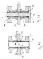
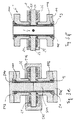
- Fig. 1 shows in perspective in longitudinal section a magnetic-inductive flow sensor and Fig. 2 shows schematically in cross section a substantial part of the fürflußaufitess.
- the fürflußaufsacrificing comprises a straight measuring tube 1 of predetermined shape and size for guiding a flowing fluid, arranged on the measuring tube 1 magnetic circuit arrangement 2 for guiding a magnetic field through the fluid and also arranged on the measuring tube 1 electrode assembly 3 for measuring a voltage induced in the fluid.
- the measuring tube 1 For pressure-tight insertion into a pipe through which a fluid can flow, the measuring tube 1 has an inlet-side first end and an outlet-side second end.
- the measuring tube 1 comprises a carrier tube 11 of predeterminable lumen and a tubular, consisting of an insulating liner 12 of predeterminable width and embedded in the liner 12, open-pored support body 13 of predeterminable pore size and thickness.
- the likewise tubular support body 13 is used for mechanical stabilization of the liner 12, esp. At temperatures of the flowing fluid from -40 ° C to 200 ° in a pressure range of 0 bar to 40 bar.
- the support tube 11 encloses the liner 12 with embedded support body 13 coaxial and thus serves as an outer shaping and dimensionally stabilizing enclosure measuring tube. 1
- the measuring tube 1 is designed so that the support tube 11 and the support body 13 inside is completely covered by the liner 12 and thus only the liner 12 is wetted by flowing through the measuring tube 1 fluid, see. this also the US-A 32 13 685 ,
- Fig. 3a to 3f show in longitudinal section a respective current state of the fürflußauf choirs during various process steps in the production.
- the carrier tube 11 is shown at the beginning of the method of the invention. It is preferably produced inexpensively as a casting, which is subsequently finished, for example, by machining processes such as milling, turning and / or drilling; Of course, it can also be manufactured exclusively by cutting processes or other manufacturing processes known to those skilled in the art for pipes.
- materials for the support tube 11 are all commonly used in fürparßaufêtn stainless steels, esp. Alloyed and high-alloy stainless steels are used; however, it is also possible to use other non-ferromagnetic alloys, such as, for example, copper alloys, titanium alloys or nickel alloys, but also suitable plastics, such as, for example, glass-fiber-reinforced plastics.
- the support body 13 is after Fig. 1 a tubular body, which is made in a pass-fit and tight fit by in-situ sintering of granular sintered starting material specifiable particle size, ie by sintering in the final installation form and installation position, in the support tube 11.
- a first sintered mandrel 411 is introduced into the lumen of the support tube 11 and temporarily fixed there so that a first sintered space 41 running coaxially with the support tube 11 is formed by predeterminable first sintered volume.
- the sintering mandrel 411 consists of two partial mandrels, which are designed so that they abut each other after introduction into the support tube 11 with their respective end faces; Of course, the sintering mandrel 411 can also be designed in one piece in a suitable manner.
- the sintering mandrel 411 may also be non-rotationally symmetric, if necessary, e.g. elliptical or prismatic.
- the sintered mandrel 411 consists of two partial mandrels, which are correspondingly conical or are funnel-shaped and abut each other after their introduction into the support tube 11 with their smaller end faces. After the introduction of the sintering mandrel 411, the support tube 11 is closed so that only fill openings for the sintered starting material remain. These are preferably formed by a single open end of the support tube 11.
- the fixing of the sintering mandrel 411 and the closing of the sintering space 41 is usually carried out by means of an end-side first flange 412; becomes the sintering mandrel 411, as in Fig. 3b shown, also fixed at the second end by means of an end-side second flange 413, so preferably one of the two flanges 412, 413, the corresponding filling openings 414 on. It is obvious and clear that particle size, sintering volume and filling openings are to be dimensioned so that the sintered starting material can be introduced into the sintering space 41.
- Fig. 3b shown schematically filled with the sintered starting material.
- the sintered starting material is sintered in the sintering space 41, whereby the support body 13 is formed in the lumen of the support tube 11 passport-shaped, see. Fig. 3c ,
- the support tube 11 is completely sealed before sintering.
- sinter starting material serve metal particles, esp. Of sintered bronze; however, other materials such as e.g. Sintered glass particles, sintered ceramic particles or sinterable, esp. Surface-metallized, plastic particles used.
- the support body 13 consists of at least two tubular part support bodies with mutually different thermal expansion coefficients, which are arranged coaxially with each other and are non-positively connected to each other.
- the first sintering mandrel 411 used for sintering is replaced by a second sintering mandrel 421 which is temporarily fixed in the lumen of the support tube 11 such that it is coaxial with the longitudinal axis of the lumen between the sintering mandrel 421 and the ready sintered support body 13 aligned second sintered space 42 is formed by a predetermined second sintering volume; If necessary, the sintering mandrel 421 can be designed in two parts, such as the sintering mandrel 411.
- the sintering mandrel 421 has a smallest diameter larger than the smallest width of the liner 12 and a largest diameter smaller than the largest diameter of the sintering mandrel 411.
- the sintering space 42 is filled with a second sintered starting material, in particular completely, and the carrier tube 11 is then possibly completely sealed. Subsequently, the second sintered starting material is sintered in the sintering space 42, and thus a reinforced, practically consisting of two coaxial partial supporting bodies existing support body 13 is made.
- This embodiment of the support body 13 of two or more partial support bodies may e.g. also serve to optimize temperature distributions in the measuring tube 1 or to optimize the electromagnetic properties of the support body 13.
- the measuring tube 1 is lined inside with a liner 12, in such a way that support body 13 and support tube 11 are completely isolated in the operation of the fürflußaufillons from the fluid flowing therethrough.
- the liner 12 is according to Fig. 3e after manufacture of the support body 13 also made directly in the support tube 11 by filling and solidification of liquefied insulating material. This is preferably done in a conventional transfer, compression or injection molding process.
- all those used in magnetic-inductive Naturalflußaufillonstoffough strictly for the liner 12 plastics serve that can be liquefied at least once for introduction into the support tube 11, such as.
- Thermoplastics in particular fluorine-containing thermoplastics or polyolefins, or thermosets, esp. Cast resins or polyurethanes.
- the sintering mandrel 411 or 421 used in the sintering is replaced by a casting mandrel 511, which is temporarily fixed in the lumen of the support tube 11, that between the casting mandrel 511 and the support body 13 with a the longitudinal axis of the lumen coaxially aligned casting chamber 51 is formed by predetermined casting volume.
- the casting mandrel 511 is preferably cylindrical with a diameter that, under Considering a Gello volume shrinkage after solidification, at most equal to the predetermined width of the liner 12 is formed.
- the support tube 11 After introduction of the first casting mandrel 511, the support tube 11 is sealed in a pour-proof manner so that only pouring openings for the liquefied insulating material remain.
- the fixing of the casting mandrel 511 and the closing of the support tube 11 are usually carried out by means of a third and fourth end flange 512 or 513, of which e.g. one has a corresponding pour-in opening 514.
- the filling is preferably carried out until the casting chamber 51 and the support body 13 are completely filled with the insulating material, but at least until the casting chamber 51 is completely and the support body 13 at least partially filled with the insulating material.
- the insulating material completely covers the support body 13 at least at the inner side facing the fluid during operation of the flow sensor.
- the insulating material After filling, the insulating material is solidified and thus the liner 12 with embedded support body 13 in the lumen of the support tube 11 in the form of a passport formed such that it isolates the support body 13 and the support tube 11 from the fluid.
- the carrier tube 11 preferably has a first widening 111 introduced into the inlet-side first end and a second widening 112 introduced into the outlet-side second end 112.
- the two expansions 111, 112 are after Fig. 1 or 3a in sections, inwards conically tapered; but they can also be of straight cylindrical shape.
- Both widenings 111, 112 are at least partially filled in the sintering of the sintered starting material, in such a way that the sintered support body 13 is clamped to the support tube 11 and thus additionally fixed, see. Fig. 3c ,
- the widenings 111, 112 of the support body 13 are filled so that the liner 12, the support body 13 in the region of the widening 111, 112 partially surrounds and thus practically completely covered at the end, see. this the 3e and 3f ,
- the flow sensor is positioned after the Fig. 1 and 2 a magnetic circuit arrangement 2.
- This comprises a first and a second cylindrical coil 21, 22, each of which surrounds a first and a second ferromagnetic coil core 23, 24 each having a free end-side first and second end face 232, 242 of predeterminable shape.
- the coil cores are preferably designed as a single sheet metal part or as a package of several, electrically isolated from each other layered sheet metal parts, see. the JP-Y 2-28 406 or the US-A 46 41 537 ,
- the coil cores 23, 24 are connected at their respective end face 232 and 242 opposite ends with a not shown, also ferromagnetic, inference of predeterminable length and shape.
- the return is placed on both sides of the outside of the measuring tube 1, see. this the US-A 46 41 537 ,
- the coil cores 23, 24 instead of the sheet metal parts at least end of sintered ferromagnetic material, esp. From surface-metallized plastic particles.
- the coils 21, 22 are preferably each wound on a tubular, the respective coil core 23, 24 coaxially enclosing first and second bobbin 25, 26; However, the coils 21, 22 can also be self-supporting or at least partially embedded in the bobbin 25, 26. In addition to magnetic circuit arrangements with two coils and those with three or more coils are common, see. this the JP-A 3-218,414 ,
- the coils 21, 22 are connected to an exciter electronics for generating electrical currents of predeterminable current intensity and flowed through by the latter.
- Exciter electronics can be the circuits described in the prior art.
- the measuring tube 1 preferably comprises a first coil core seat 14 for the frontal insertion of the spool core 23 and a second spool core seat 15 for the frontal insertion of the spool core 24, see. the Fig. 1 and 2 ,
- the coil core seat 14, 15 preferably have a the respective end faces 231 and 241 of the coil cores 23, 24 positively touching first and second surface on which the respective associated coil core 23, 24 is applied flat.
- the support tube 11 is provided with a lateral first shell opening 113 and with a lateral second shell opening 114. Both shell openings 113, 114 preferably have the same shape and are spaced apart along a circumferential circle of the support tube 11, esp., So that they are diametrically opposed.
- the coil cores 23, 24 are inserted through the respective shell opening 113 and 114 into the measuring tube 1 and aligned with each other so that their two end faces 231, 241 spaced apart along the circumference circle, esp. Diametrically spaced and mirror image, opposite.
- the jacket openings 113, 114 or the end faces 231, 241 can also be spaced apart from one another along a chord of the circumferential circle of the measuring tube 1 and / or be arranged on the measuring tube 1 in a non-mirror-image manner, cf. JP-A 3-218,414 ,
- the shell openings 113, 114 are of course to be dimensioned so that the coil cores 23, 24 readily fit through.
- the jacket openings 113, 114 are introduced into the carrier tube 11 before insertion of the first sintered mandrel 411 and closed in a sinter-tight manner during filling and sintering of the sintered starting material for the support body 13 by means of a first or by means of a second sintered closure 415, 416, cf. Fig. 3b ,
- the two sintered closures 415, 416 are preferably designed so that the support body 13 according to Fig. 3c the two jacket openings 113, 114 at least partially completed.
- the filling of the shell openings 113, 114 is carried out, for example, so that the support body 13 laterally against the shell openings 113, 114 and is thus additionally locked.
- the two shell openings 113, 114 are filled and allowed to solidify the liquified insulating material for the liner 12, as in FIG Fig. 3e represented by a first or by means of a second pouring closure 515, 516 to seal pour-tight.
- the spatial formation of the magnetic field in the measuring volume and thus also the accuracy of naturalflußaufêts are determined by the mutual distance of the end faces of the coil cores.
- the influence of disturbances in the fluid e.g. based on changes in the flow behavior or on temperature fluctuations, on a measurement signal obtained with the fürflußaufêt.
- the sensitivity of the flow sensor to changes in the volume flow to be measured becomes greater. It is optimal when the two faces are as close as possible to each other.
- the first and the second spool core seat 14, 15 are formed in the support body 13 with a predeterminable depth so that their surfaces face each other with a predeterminable distance.
- the coil cores 23, 24 with an end, at their end faces 231, 241 adjacent first and second coil core portion 232 and 242 in the coil core seat 14 and 15 used and thus their end faces 231, 241 with a predetermined, from the selected thickness of the support body 13 practically independent, mutual distance on the measuring tube 1 can be positioned.
- the two end faces 231, 241 and the adjacent thereto end-side coil core section 232, 242 according to Fig. 2 Polschuhartig formed with specifiable shape and area.
- the end faces 231, 241 are then preferably of arched or curved shape and have a uniform and to the lumen of the measuring tube 1 towards convex curvature.
- This shaping of the sintered closures 415, 416 and the pouring closures 515, 516 is particularly advantageous in that the coil core 23 or 24, as in FIG Fig. 3b shown, is temporarily inserted before sintering in the sintered closure 415 and 416 and before the filling of the liquefied insulating material in the pouring closure 515 and 516, cf. Fig. 3e , As a result, the coil cores 23, 24 after completion of the measuring tube 1 in the support body 13 and the liner 12 end side, esp. Formed and non-positively, embedded.
- the spools 21 and 22 are preferably arranged on the spool core 23 and 24, respectively, prior to the filling of the insulating material.
- the pouring closures 515, 516 are after Fig. 3e pot-shaped so that the insulating material through the support body 13 and the shell openings 113, 114 passes out of the support tube 11 and that after the solidification of the insulating material, the coil 21 or 22 at least partially embedded therein and thus practically the bobbin 25 and 26 are formed, see. 3f. If the pores of the support body 13 do not allow a sufficiently rapid filling of the shell openings 113, 114, appropriate passageways are to be provided in the support body 13, preferably during sintering.
- the coil core seats 14, 15 in their shape and size in such a way that the associated coil core 23 and 24 can be fitted easily.
- additional webs and shoulders may be formed in the shell openings 113, 114 during their production, against which the support body 13 or the liner 12 is supported.
- the von Hearter For tapping a voltage induced in the fluid, the von Heartersacrificing after the Fig. 1 and 2 a mounted on the measuring tube 1 sensor assembly 3, which comprises a first and a second electrode 31, 32.
- the electrodes are preferably rod-shaped with a first or a second electrode head 311, 321 for tapping the induced voltage mentioned in the introduction and with a first or a second electrode shaft 312, 322, which connects the sensor arrangement to an evaluation electrode. Electronics serves, educated.
- the electrodes 31, 32 may, as in Fig. 2 represented, galvanic or even capacitive electrodes.
- the support tube 11 is therefore further provided with a lateral third and fourth shell opening 115, 116 for the insertion of the electrode 31 and 32, respectively.
- the jacket openings 115, 116 have a width that is greater than a largest diameter of the respective electrode shaft 312 or 322. They preferably have the same shape and are preferably diametrically opposite one another, wherein a diameter of the carrier tube 11 connecting the jacket openings 115, 116 extends perpendicularly to a diameter of the carrier tube 11 connecting the jacket openings 113, 114.
- the electrodes 31, 32 if necessary, esp. In more than two electrodes on the measuring tube 1 are spaced from each other so that they are not diametrically opposed. This is the case, for example, if additional electrodes for reference potentials or In the horizontal mounting position of the measuring tube 1 electrodes for monitoring a minimum level of the fluid in the measuring tube 1 are provided.
- the jacket openings 115, 116 are sealed in a sinter-tight manner by means of a third or not shown fourth sintering mandrel after inserting the first sintered mandrel 411.
- Closing the sheath openings 115, 116 is preferably carried out so that the third and the fourth mandrel reach to the sintering mandrel 411, whereby after sintering of the support body 13, the two shell openings 115, 116 continue in this consistently, cf. Fig. 2 ,
- the third and fourth mandrel each have a smallest diameter, which is at least slightly larger than a largest diameter of the first and second electrode shank.
- the jacket openings 115, 116 and their extension in the support body for the filling of the insulating material with a third or a fourth pouring closure preferably pour-tight so closed that after the solidification of the insulating material, the measuring tube 1, starting from the respective shell opening 115 and 116 , having a first and a second electrode leadthrough.
- the casting-tight closure of the shell openings 115, 116 is preferably carried out so that the electrode bushings are completely covered on the inside and with a predetermined minimum thickness of the insulating material and thus already during the production of the liner 12 electrically insulated electrode bushings for the subsequently used Electrodes are created.
- the third or fourth G tellverschlußes is taking into account the Gello volume shrinkage, in a suitable manner in such a way that after the solidification of the solving already pass-shaped, the electrode shafts 312, 322 corresponding electrode bushings are formed in the measuring tube 1.
- the pouring closures in a particularly advantageous manner be executed that in these the electrodes 31, 32 are used so that they are already placed after filling and solidification of the insulating material in its final installation position in the measuring tube 1 and thereby of the insulating material the liner 12 against the support body 13 and the support tube 11 and in operation against the fluid are completely electrically isolated.
- the electrode shafts 312, 322 are preferably prismatic, in particular parallelepiped-shaped, within the electrode lead-through, whereby the electrodes 31, 32 can be easily mounted without a counter-tool in the lumen of the measuring tube 1.
- the sinter-proof or pour-proof sealing of the corresponding electrode openings takes place before the sintering of the support body or before the filling of the insulating material in an analogous manner with corresponding cast or sintered closures.
- the softening temperature of the support tube 11 must be greater than that of the support body 13 and the latter in turn must be greater than the melting temperature of the liner 12.
Landscapes
- Physics & Mathematics (AREA)
- Fluid Mechanics (AREA)
- General Physics & Mathematics (AREA)
- Electromagnetism (AREA)
- Engineering & Computer Science (AREA)
- Power Engineering (AREA)
- Measuring Volume Flow (AREA)
- Geophysics And Detection Of Objects (AREA)
- Powder Metallurgy (AREA)
- Casting Or Compression Moulding Of Plastics Or The Like (AREA)
- Investigating Or Analyzing Materials By The Use Of Magnetic Means (AREA)
Claims (6)
- Débitmètre magnéto-inductif, comprenant :- un tube de mesure (1) insérable de façon étanche à la pression dans une conduite, présentant côté entrée une première extrémité et côté sortie une deuxième extrémité, lequel tube comporte-- un tube support (11) non ferromagnétique servant d'enveloppe extérieure du tube de mesure (1),-- un liner (12) tubulaire constitué d'un matériau isolant, logé dans un canal intérieur du tube support (11), lequel liner est destiné à acheminer un fluide en écoulement et est isolé par rapport au tube support (11), et-- un corps d'appui (13) à pores ouverts destiné à la stabilisation du liner (12) et incorporé dans ce dernier,- un circuit magnétique (2) disposé sur le tube de mesure (1), destiné à générer et à guider un champ magnétique, qui induit un champ électrique dans le fluide en écoulement, lequel circuit comprend-- une première bobine (21),-- une deuxième bobine (22),-- un premier noyau de bobine ferromagnétique (23) couplé magnétiquement aux bobines (21, 22), présentant une surface frontale d'extrémité (231) au moins partiellement bombée, et-- un deuxième noyau de bobine ferromagnétique (24) couplé magnétiquement aux bobines (21, 22), présentant une surface frontale d'extrémité (241) au moins partiellement bombée, et- une première électrode (31) et une deuxième électrode (32) pour le prélèvement d'une tension du champ électrique,- un premier et un deuxième logement de noyau de bobine étant formés dans le corps d'appui avec une profondeur prédéfinissable,-- le premier noyau de bobine (23) étant introduit avec une première section de noyau de bobine d'extrémité (232) partant de l'une des ses surfaces frontales (231), à travers une première ouverture d'enveloppe (113) du tube support (11), dans le premier logement de noyau de bobine (14) du corps support (13), de telle sorte que la première surface frontale (231) repose par complémentarité de forme contre une première surface du logement de noyau de bobine (14), et-- le deuxième noyau de bobine (24) étant introduit avec une deuxième section de noyau de bobine d'extrémité (242) partant de l'une des ses surfaces frontales (241), à travers une deuxième ouverture d'enveloppe (114) du tube support (11), dans le deuxième logement de noyau de bobine (15) du corps support (13), de telle sorte que la deuxième surface frontale (241) repose par complémentarité de forme contre une deuxième surface du logement de noyau de bobine (15).
- Débitmètre selon la revendication 1, pour lequel le premier logement de noyau de bobine (14) entoure au moins partiellement par complémentarité de forme la première section de noyau de bobine (232) ou pour lequel le deuxième logement de noyau de bobine (15) entoure au moins partiellement par complémentarité de forme la deuxième section de noyau de bobine (242).
- Débitmètre selon la revendication 1 ou 2, pour lequel la première section de noyau de bobine (232) et la deuxième section de noyau de bobine (242) sont formées en tant qu'épanouissement polaire.
- Débitmètre selon l'une des revendications précédentes, pour lequel le corps d'appui (13) est une pièce formée, notamment directement dans tube le support, et frittée, notamment selon plusieurs couches de frittage.
- Débitmètre selon l'une des revendications précédentes, pour lequel le liner (12) est une pièce en fonte moulée ou moulée par injection, qui entoure le premier et le deuxième noyau de bobine (23, 24) au moins partiellement par complémentarité de forme.
- Débitmètre selon la revendication précédente, pour lequel la première bobine (21) est disposée sur le premier noyau de bobine (23) ou la deuxième bobine (22) sur le deuxième noyau de bobine (24), et incorporée au moins partiellement dans le matériau isolant du liner (12).
Priority Applications (1)
| Application Number | Priority Date | Filing Date | Title |
|---|---|---|---|
| EP08163861.1A EP2012096B1 (fr) | 1999-03-26 | 1999-03-26 | Capteur de débit magnétique-inductif |
Applications Claiming Priority (2)
| Application Number | Priority Date | Filing Date | Title |
|---|---|---|---|
| EP19990105159 EP1039269B1 (fr) | 1999-03-26 | 1999-03-26 | Procédé de fabrication d'un capteur électromagnétique de débit |
| EP08163861.1A EP2012096B1 (fr) | 1999-03-26 | 1999-03-26 | Capteur de débit magnétique-inductif |
Related Parent Applications (1)
| Application Number | Title | Priority Date | Filing Date |
|---|---|---|---|
| EP19990105159 Division EP1039269B1 (fr) | 1999-03-26 | 1999-03-26 | Procédé de fabrication d'un capteur électromagnétique de débit |
Publications (2)
| Publication Number | Publication Date |
|---|---|
| EP2012096A1 EP2012096A1 (fr) | 2009-01-07 |
| EP2012096B1 true EP2012096B1 (fr) | 2016-10-26 |
Family
ID=8237767
Family Applications (2)
| Application Number | Title | Priority Date | Filing Date |
|---|---|---|---|
| EP19990105159 Expired - Lifetime EP1039269B1 (fr) | 1999-03-26 | 1999-03-26 | Procédé de fabrication d'un capteur électromagnétique de débit |
| EP08163861.1A Expired - Lifetime EP2012096B1 (fr) | 1999-03-26 | 1999-03-26 | Capteur de débit magnétique-inductif |
Family Applications Before (1)
| Application Number | Title | Priority Date | Filing Date |
|---|---|---|---|
| EP19990105159 Expired - Lifetime EP1039269B1 (fr) | 1999-03-26 | 1999-03-26 | Procédé de fabrication d'un capteur électromagnétique de débit |
Country Status (5)
| Country | Link |
|---|---|
| EP (2) | EP1039269B1 (fr) |
| JP (1) | JP3172159B2 (fr) |
| CN (1) | CN1192210C (fr) |
| DE (1) | DE59914903D1 (fr) |
| DK (1) | DK1039269T3 (fr) |
Families Citing this family (33)
| Publication number | Priority date | Publication date | Assignee | Title |
|---|---|---|---|---|
| US6658720B1 (en) * | 1999-03-26 | 2003-12-09 | Endress + Hauser Flowtec Ag | Method of manufacturing an electromagnetic flow sensor |
| DE10306522A1 (de) * | 2003-02-14 | 2004-08-26 | Endress + Hauser Flowtec Ag, Reinach | Montagepaket für die Herstellung eines magnetisch-induktiven Durchflußmessers |
| WO2005057141A1 (fr) * | 2003-12-11 | 2005-06-23 | Endress+Hauser Flowtec Ag | Capteur de debit magneto-inductif et procede de fabrication |
| JP4893920B2 (ja) * | 2005-07-15 | 2012-03-07 | 横河電機株式会社 | 電磁流量計 |
| DE102005046319A1 (de) | 2005-09-27 | 2007-03-29 | Endress + Hauser Flowtec Ag | Verfahren zum Messen eines in einer Rohrleitung strömenden Mediums sowie Meßsystem dafür |
| DE102006015074B4 (de) * | 2006-03-31 | 2008-06-12 | Abb Ag | Magnetisch-induktiver Durchflussmesser mit einer Isolierschicht und Verfahren zu dessen Herstellung |
| WO2007125018A1 (fr) * | 2006-04-27 | 2007-11-08 | Endress+Hauser Flowtec Ag | Capteur de mesure à induction magnétique |
| DE102006062600B4 (de) | 2006-12-29 | 2023-12-21 | Endress + Hauser Flowtec Ag | Verfahren zum Inbetriebnehmen und/oder Überwachen eines In-Line-Meßgeräts |
| DE102007030691A1 (de) | 2007-06-30 | 2009-01-02 | Endress + Hauser Flowtec Ag | Meßsystem für ein in einer Prozeßleitung strömendes Medium |
| DE102007030690A1 (de) | 2007-06-30 | 2009-05-07 | Endress + Hauser Flowtec Ag | Meßsystem für ein in einer Prozeßleitung strömendes Medium |
| DE102007030699A1 (de) | 2007-06-30 | 2009-01-15 | Endress + Hauser Flowtec Ag | Meßsystem für ein in einer Prozeßleitung strömendes Medium |
| DE102007030700A1 (de) | 2007-06-30 | 2009-05-07 | Endress + Hauser Flowtec Ag | Meßsystem für ein in einer Prozeßleitung strömendes Medium |
| DE102007063372A1 (de) | 2007-12-30 | 2009-07-02 | Endress + Hauser Flowtec Ag | Meßsystem für ein in einer Prozeßleitung strömendes Medium |
| DE102007037166A1 (de) | 2007-08-07 | 2009-02-19 | Endress + Hauser Flowtec Ag | Meßgerät |
| DE102007038507A1 (de) * | 2007-08-14 | 2009-02-19 | Endress + Hauser Flowtec Ag | Rohrleitung bzw. Messrohr mit mindestens einer, mindestens bereichsweise isolierenden Schicht und Verfahren zu dessen Herstellung |
| DE102008016235A1 (de) | 2008-03-27 | 2009-10-01 | Endress + Hauser Flowtec Ag | Verfahren zum Betreiben eines auf einer rotierenden Karussell-Abfüllmachine angeordneten Meßgeräts |
| DE102009002289A1 (de) | 2009-04-08 | 2010-10-14 | Endress + Hauser Flowtec Ag | Verfahren zum Ermitteln einer Periodendauer eines Meßsignals |
| DE102009018056B4 (de) * | 2009-04-21 | 2011-01-20 | Qundis Gmbh | Wasser-/Wärmezähler mit einem Gebergehäuse und Verfahren zur Herstellung eines Gebergehäuses |
| US9521941B2 (en) | 2012-08-21 | 2016-12-20 | Premark Feg L.L.C. | Warewash machine chemical sensor and related system and method |
| DE102012112388A1 (de) * | 2012-12-17 | 2014-07-03 | Endress + Hauser Conducta Gesellschaft für Mess- und Regeltechnik mbH + Co. KG | Induktiver Leitfähigkeitssensor und Verfahren zu dessen Herstellung |
| WO2015055303A1 (fr) * | 2013-10-17 | 2015-04-23 | Krohne Ag | Système de mesure de débit magnéto-inductif |
| DE102013114428A1 (de) | 2013-12-19 | 2015-06-25 | Endress + Hauser Flowtec Ag | Messrohr für ein magnetisch-induktives Durchflussmessgerät und Magnetisch-induktives Durchflussmessgerät |
| DE102013114429A1 (de) * | 2013-12-19 | 2015-06-25 | Endress + Hauser Flowtec Ag | Messrohr für ein magnetisch-induktives Durchflussmessgerät und Magnetisch-induktives Durchflussmessgerät |
| DE102015107119A1 (de) | 2015-05-07 | 2016-11-10 | Endress + Hauser Flowtec Ag | Messrohr und Magnetisch-induktives Durchflussmessgerät |
| US10502599B2 (en) * | 2016-03-31 | 2019-12-10 | Rosemount Inc. | Polymeric magnetic flowmeter flow body assembly |
| EP3517899A4 (fr) * | 2017-04-28 | 2019-08-28 | Aichi Tokei Denki Co., Ltd. | Débitmètre électromagnétique |
| DE102017130717A1 (de) * | 2017-12-20 | 2019-06-27 | Endress+Hauser Flowtec Ag | Fertigungsverfahren zur Herstellung eines magnetisch-induktiven Durchflussmessgerätes und magnetisch-induktives Durchflussmessgerät |
| DE102018115629A1 (de) * | 2018-06-28 | 2020-01-02 | Endress+Hauser Flowtec Ag | Magnetisch-induktives Durchflussmessgerät und ein Verfahren, zum Herstellen eines solchen magnetisch-induktiven Durchfluss-messgerätes |
| EP3963292B1 (fr) * | 2019-05-03 | 2024-11-27 | Kamstrup A/S | Tube d'écoulement et boîtier pour débitmètre |
| US11365994B2 (en) * | 2020-06-19 | 2022-06-21 | Micro Motion, Inc. | Magnetic flowmeter flow tube assembly liner |
| KR102432201B1 (ko) * | 2020-09-02 | 2022-08-16 | 한국유체기술(주) | 착탈식 전극을 구비한 전자식 유량계 |
| CN113483938B (zh) * | 2021-06-29 | 2022-05-17 | 班宁(南京)传感技术有限公司 | 一种高精度数显压力变送器及检测方法 |
| CN114674383B (zh) * | 2022-04-03 | 2025-03-11 | 杭州云谷科技股份有限公司 | 小型化电磁流量传感器的电极和引出装置 |
Family Cites Families (15)
| Publication number | Priority date | Publication date | Assignee | Title |
|---|---|---|---|---|
| US3213685A (en) | 1962-01-23 | 1965-10-26 | Fischer & Porter Co | Magnetic flowmeter |
| JPS5351181Y2 (fr) | 1973-02-16 | 1978-12-07 | ||
| EP0047342B1 (fr) * | 1980-09-04 | 1984-01-11 | Rheometron Ag | Tête de mesure pour débitmètres électromagnétiques |
| US4470309A (en) * | 1981-07-06 | 1984-09-11 | Tokyo Shibaura Denki Kabushiki Kaisha | Electromagnetic flowmeter |
| GB2118477B (en) * | 1982-04-14 | 1985-10-30 | Fischer & Porter Co | Injection molding a liner onto spool |
| JPS59137822A (ja) | 1983-01-28 | 1984-08-08 | Yamatake Honeywell Co Ltd | 電磁流量計の検出管製造方法 |
| JPS59128525U (ja) | 1983-02-02 | 1984-08-29 | 株式会社東芝 | 電磁流量計検出器 |
| DE3501768A1 (de) | 1985-01-21 | 1986-07-24 | Danfoss A/S, Nordborg | Elektromagnetischer durchflussmesser |
| JPS63145919A (ja) * | 1986-07-28 | 1988-06-18 | Toshiba Corp | 電磁流量計検出器 |
| DE3702062C1 (de) * | 1987-01-24 | 1988-05-19 | B & S Metalpraecis Gmbh | Rohrpassstueck |
| JPH03218414A (ja) | 1990-01-24 | 1991-09-26 | Yamatake Honeywell Co Ltd | 電磁流量計 |
| JPH03276023A (ja) * | 1990-03-27 | 1991-12-06 | Yokogawa Electric Corp | セラミックス電磁流量計 |
| NL9201342A (nl) * | 1992-07-24 | 1994-02-16 | Krohne Altometer | Meetinstrument met versterkte voering. |
| DE59500366D1 (de) | 1995-09-22 | 1997-08-14 | Flowtec Ag | Verfahren zum Herstellen eines Messrohrs eines magnetisch-induktiven Durchflussaufnehmers |
| GB2328021B (en) * | 1997-08-01 | 2001-11-28 | Abb Kent Taylor Ltd | Electromagnetic flow sensor and assembly method |
-
1999
- 1999-03-26 EP EP19990105159 patent/EP1039269B1/fr not_active Expired - Lifetime
- 1999-03-26 DK DK99105159T patent/DK1039269T3/da active
- 1999-03-26 EP EP08163861.1A patent/EP2012096B1/fr not_active Expired - Lifetime
- 1999-03-26 DE DE59914903T patent/DE59914903D1/de not_active Expired - Lifetime
-
2000
- 2000-03-24 CN CNB001046608A patent/CN1192210C/zh not_active Expired - Fee Related
- 2000-03-27 JP JP2000087605A patent/JP3172159B2/ja not_active Expired - Fee Related
Non-Patent Citations (1)
| Title |
|---|
| None * |
Also Published As
| Publication number | Publication date |
|---|---|
| DE59914903D1 (de) | 2008-12-24 |
| CN1274076A (zh) | 2000-11-22 |
| EP2012096A1 (fr) | 2009-01-07 |
| JP2000292229A (ja) | 2000-10-20 |
| JP3172159B2 (ja) | 2001-06-04 |
| DK1039269T3 (da) | 2009-03-09 |
| CN1192210C (zh) | 2005-03-09 |
| EP1039269A1 (fr) | 2000-09-27 |
| EP1039269B1 (fr) | 2008-11-12 |
Similar Documents
| Publication | Publication Date | Title |
|---|---|---|
| EP2012096B1 (fr) | Capteur de débit magnétique-inductif | |
| EP0764831A1 (fr) | Procédé de fabrication d'un tube de mesure pour un capteur électromagnétique de débit | |
| US6658720B1 (en) | Method of manufacturing an electromagnetic flow sensor | |
| EP0309932B1 (fr) | Débitmètre électromagnétique | |
| EP2583067B1 (fr) | Procede de production d'un débitmètre magnéto-inductif | |
| DE4119903C5 (de) | Verfahren und Vorrichtung zur Messung dünner Schichten | |
| DE4017260C2 (de) | Verfahren zum Herstellen einer Sattelspulen-Anordnung für ein Gradientenmagnetfeld einer MRI-Apparatur | |
| DE10014348B4 (de) | Vorrichtung zur zerstörungsfreien Messung der Dicke dünner Schichten | |
| EP3555573B1 (fr) | Tube de mesure pour appareil de mesure ou appareil de mesure formé au moyen d'un tel tube de mesure et procédé de fabrication d'un tel tube de mesure | |
| EP1692465B1 (fr) | Capteur de debit magneto-inductif et procede de fabrication | |
| EP1756531B1 (fr) | Capteur de debit a induction magnetique | |
| DE10358268A1 (de) | Magnetisch-induktiver Durchflußaufnehmer und Verfahren zu dessen Herstellung | |
| EP1592950B1 (fr) | Ensemble de montage pour produire un debitmetre magneto-inductif | |
| EP1151251B1 (fr) | Debitmetre electromagnetique et procede permettant de le produire | |
| DE3627993A1 (de) | Elektromagnetischer durchflussmesser | |
| EP2010869A1 (fr) | Capteur de mesure à induction magnétique | |
| EP0306895B1 (fr) | Procédé de fabrication d'un tuyau de mesure pour la mesure magnéto-inductive de débit | |
| EP4062129A1 (fr) | Débitmètre à induction magnétique | |
| DE102005060208A1 (de) | Messaufnehmer eines magnetisch induktiven Durchflussmessgeräts | |
| DE102015116676A1 (de) | Magnetisch-induktives Durchflussmessgerät und Verfahren zum Herstellen einer Messelektrode | |
| DE10322082A1 (de) | Magnetisch-induktiver Durchflußaufnehmer | |
| EP3048431B1 (fr) | Débitmètre magnéto-inductif et procédé de fabrication d'une électrode de mesure | |
| DE3435910A1 (de) | Magnetisch-induktiver durchflussmesser mit auswechselbaren durchflusssensoren | |
| EP4627296A1 (fr) | Procédé de fabrication d'un élément de sonde et élément de sonde | |
| WO2024022652A1 (fr) | Débitmètre magnéto-inductif |
Legal Events
| Date | Code | Title | Description |
|---|---|---|---|
| PUAI | Public reference made under article 153(3) epc to a published international application that has entered the european phase |
Free format text: ORIGINAL CODE: 0009012 |
|
| AC | Divisional application: reference to earlier application |
Ref document number: 1039269 Country of ref document: EP Kind code of ref document: P |
|
| AK | Designated contracting states |
Kind code of ref document: A1 Designated state(s): CH DE DK ES FR GB IT LI NL |
|
| 17P | Request for examination filed |
Effective date: 20090119 |
|
| R17P | Request for examination filed (corrected) |
Effective date: 20090114 |
|
| 17Q | First examination report despatched |
Effective date: 20090219 |
|
| AKX | Designation fees paid |
Designated state(s): CH DE DK ES FR GB IT LI NL |
|
| REG | Reference to a national code |
Ref country code: DE Ref legal event code: R079 Ref document number: 59915452 Country of ref document: DE Free format text: PREVIOUS MAIN CLASS: G01F0001580000 Ipc: G01F0015140000 |
|
| GRAP | Despatch of communication of intention to grant a patent |
Free format text: ORIGINAL CODE: EPIDOSNIGR1 |
|
| RIC1 | Information provided on ipc code assigned before grant |
Ipc: G01F 1/58 20060101ALI20160704BHEP Ipc: G01F 15/14 20060101AFI20160704BHEP |
|
| INTG | Intention to grant announced |
Effective date: 20160718 |
|
| RIN1 | Information on inventor provided before grant (corrected) |
Inventor name: MAGLIOCCA, ANTONIO Inventor name: FREY, DANIEL |
|
| GRAS | Grant fee paid |
Free format text: ORIGINAL CODE: EPIDOSNIGR3 |
|
| GRAA | (expected) grant |
Free format text: ORIGINAL CODE: 0009210 |
|
| AC | Divisional application: reference to earlier application |
Ref document number: 1039269 Country of ref document: EP Kind code of ref document: P |
|
| AK | Designated contracting states |
Kind code of ref document: B1 Designated state(s): CH DE DK ES FR GB IT LI NL |
|
| REG | Reference to a national code |
Ref country code: GB Ref legal event code: FG4D Free format text: NOT ENGLISH |
|
| REG | Reference to a national code |
Ref country code: CH Ref legal event code: EP |
|
| REG | Reference to a national code |
Ref country code: DE Ref legal event code: R096 Ref document number: 59915452 Country of ref document: DE |
|
| REG | Reference to a national code |
Ref country code: NL Ref legal event code: MP Effective date: 20161026 |
|
| REG | Reference to a national code |
Ref country code: FR Ref legal event code: PLFP Year of fee payment: 19 |
|
| PG25 | Lapsed in a contracting state [announced via postgrant information from national office to epo] |
Ref country code: NL Free format text: LAPSE BECAUSE OF FAILURE TO SUBMIT A TRANSLATION OF THE DESCRIPTION OR TO PAY THE FEE WITHIN THE PRESCRIBED TIME-LIMIT Effective date: 20161026 Ref country code: ES Free format text: LAPSE BECAUSE OF FAILURE TO SUBMIT A TRANSLATION OF THE DESCRIPTION OR TO PAY THE FEE WITHIN THE PRESCRIBED TIME-LIMIT Effective date: 20161026 |
|
| REG | Reference to a national code |
Ref country code: DE Ref legal event code: R097 Ref document number: 59915452 Country of ref document: DE |
|
| PG25 | Lapsed in a contracting state [announced via postgrant information from national office to epo] |
Ref country code: DK Free format text: LAPSE BECAUSE OF FAILURE TO SUBMIT A TRANSLATION OF THE DESCRIPTION OR TO PAY THE FEE WITHIN THE PRESCRIBED TIME-LIMIT Effective date: 20161026 |
|
| PG25 | Lapsed in a contracting state [announced via postgrant information from national office to epo] |
Ref country code: IT Free format text: LAPSE BECAUSE OF FAILURE TO SUBMIT A TRANSLATION OF THE DESCRIPTION OR TO PAY THE FEE WITHIN THE PRESCRIBED TIME-LIMIT Effective date: 20161026 |
|
| PLBE | No opposition filed within time limit |
Free format text: ORIGINAL CODE: 0009261 |
|
| STAA | Information on the status of an ep patent application or granted ep patent |
Free format text: STATUS: NO OPPOSITION FILED WITHIN TIME LIMIT |
|
| 26N | No opposition filed |
Effective date: 20170727 |
|
| REG | Reference to a national code |
Ref country code: CH Ref legal event code: PL |
|
| PG25 | Lapsed in a contracting state [announced via postgrant information from national office to epo] |
Ref country code: LI Free format text: LAPSE BECAUSE OF NON-PAYMENT OF DUE FEES Effective date: 20170331 Ref country code: CH Free format text: LAPSE BECAUSE OF NON-PAYMENT OF DUE FEES Effective date: 20170331 |
|
| REG | Reference to a national code |
Ref country code: FR Ref legal event code: PLFP Year of fee payment: 20 |
|
| PGFP | Annual fee paid to national office [announced via postgrant information from national office to epo] |
Ref country code: GB Payment date: 20180321 Year of fee payment: 20 Ref country code: DE Payment date: 20180322 Year of fee payment: 20 |
|
| PGFP | Annual fee paid to national office [announced via postgrant information from national office to epo] |
Ref country code: FR Payment date: 20180330 Year of fee payment: 20 |
|
| REG | Reference to a national code |
Ref country code: DE Ref legal event code: R071 Ref document number: 59915452 Country of ref document: DE |
|
| REG | Reference to a national code |
Ref country code: GB Ref legal event code: PE20 Expiry date: 20190325 |
|
| PG25 | Lapsed in a contracting state [announced via postgrant information from national office to epo] |
Ref country code: GB Free format text: LAPSE BECAUSE OF EXPIRATION OF PROTECTION Effective date: 20190325 |