EP2013456B1 - Vorrichtung zur zufuhr eines reduktionsmittels in einen abgasstrang einer verbrennungskraftmaschine - Google Patents
Vorrichtung zur zufuhr eines reduktionsmittels in einen abgasstrang einer verbrennungskraftmaschine Download PDFInfo
- Publication number
- EP2013456B1 EP2013456B1 EP20070726666 EP07726666A EP2013456B1 EP 2013456 B1 EP2013456 B1 EP 2013456B1 EP 20070726666 EP20070726666 EP 20070726666 EP 07726666 A EP07726666 A EP 07726666A EP 2013456 B1 EP2013456 B1 EP 2013456B1
- Authority
- EP
- European Patent Office
- Prior art keywords
- reducing agent
- pressure
- line
- metering device
- feed pump
- Prior art date
- Legal status (The legal status is an assumption and is not a legal conclusion. Google has not performed a legal analysis and makes no representation as to the accuracy of the status listed.)
- Ceased
Links
Images
Classifications
-
- B—PERFORMING OPERATIONS; TRANSPORTING
- B01—PHYSICAL OR CHEMICAL PROCESSES OR APPARATUS IN GENERAL
- B01D—SEPARATION
- B01D53/00—Separation of gases or vapours; Recovering vapours of volatile solvents from gases; Chemical or biological purification of waste gases, e.g. engine exhaust gases, smoke, fumes, flue gases, aerosols
- B01D53/34—Chemical or biological purification of waste gases
- B01D53/92—Chemical or biological purification of waste gases of engine exhaust gases
- B01D53/94—Chemical or biological purification of waste gases of engine exhaust gases by catalytic processes
- B01D53/9404—Removing only nitrogen compounds
- B01D53/9409—Nitrogen oxides
- B01D53/9431—Processes characterised by a specific device
-
- B—PERFORMING OPERATIONS; TRANSPORTING
- B01—PHYSICAL OR CHEMICAL PROCESSES OR APPARATUS IN GENERAL
- B01D—SEPARATION
- B01D53/00—Separation of gases or vapours; Recovering vapours of volatile solvents from gases; Chemical or biological purification of waste gases, e.g. engine exhaust gases, smoke, fumes, flue gases, aerosols
- B01D53/34—Chemical or biological purification of waste gases
- B01D53/74—General processes for purification of waste gases; Apparatus or devices specially adapted therefor
- B01D53/86—Catalytic processes
- B01D53/90—Injecting reactants
-
- F—MECHANICAL ENGINEERING; LIGHTING; HEATING; WEAPONS; BLASTING
- F01—MACHINES OR ENGINES IN GENERAL; ENGINE PLANTS IN GENERAL; STEAM ENGINES
- F01N—GAS-FLOW SILENCERS OR EXHAUST APPARATUS FOR MACHINES OR ENGINES IN GENERAL; GAS-FLOW SILENCERS OR EXHAUST APPARATUS FOR INTERNAL-COMBUSTION ENGINES
- F01N3/00—Exhaust or silencing apparatus having means for purifying, rendering innocuous, or otherwise treating exhaust
- F01N3/08—Exhaust or silencing apparatus having means for purifying, rendering innocuous, or otherwise treating exhaust for rendering innocuous
- F01N3/10—Exhaust or silencing apparatus having means for purifying, rendering innocuous, or otherwise treating exhaust for rendering innocuous by thermal or catalytic conversion of noxious components of exhaust
- F01N3/18—Exhaust or silencing apparatus having means for purifying, rendering innocuous, or otherwise treating exhaust for rendering innocuous by thermal or catalytic conversion of noxious components of exhaust characterised by methods of operation; Control
- F01N3/20—Exhaust or silencing apparatus having means for purifying, rendering innocuous, or otherwise treating exhaust for rendering innocuous by thermal or catalytic conversion of noxious components of exhaust characterised by methods of operation; Control specially adapted for catalytic conversion
- F01N3/206—Adding periodically or continuously substances to exhaust gases for promoting purification, e.g. catalytic material in liquid form, NOx reducing agents
- F01N3/2066—Selective catalytic reduction [SCR]
-
- F—MECHANICAL ENGINEERING; LIGHTING; HEATING; WEAPONS; BLASTING
- F01—MACHINES OR ENGINES IN GENERAL; ENGINE PLANTS IN GENERAL; STEAM ENGINES
- F01N—GAS-FLOW SILENCERS OR EXHAUST APPARATUS FOR MACHINES OR ENGINES IN GENERAL; GAS-FLOW SILENCERS OR EXHAUST APPARATUS FOR INTERNAL-COMBUSTION ENGINES
- F01N3/00—Exhaust or silencing apparatus having means for purifying, rendering innocuous, or otherwise treating exhaust
- F01N3/08—Exhaust or silencing apparatus having means for purifying, rendering innocuous, or otherwise treating exhaust for rendering innocuous
- F01N3/10—Exhaust or silencing apparatus having means for purifying, rendering innocuous, or otherwise treating exhaust for rendering innocuous by thermal or catalytic conversion of noxious components of exhaust
- F01N3/18—Exhaust or silencing apparatus having means for purifying, rendering innocuous, or otherwise treating exhaust for rendering innocuous by thermal or catalytic conversion of noxious components of exhaust characterised by methods of operation; Control
- F01N3/20—Exhaust or silencing apparatus having means for purifying, rendering innocuous, or otherwise treating exhaust for rendering innocuous by thermal or catalytic conversion of noxious components of exhaust characterised by methods of operation; Control specially adapted for catalytic conversion
- F01N3/206—Adding periodically or continuously substances to exhaust gases for promoting purification, e.g. catalytic material in liquid form, NOx reducing agents
- F01N3/208—Control of selective catalytic reduction [SCR], e.g. by adjusting the dosing of reducing agent
-
- F—MECHANICAL ENGINEERING; LIGHTING; HEATING; WEAPONS; BLASTING
- F01—MACHINES OR ENGINES IN GENERAL; ENGINE PLANTS IN GENERAL; STEAM ENGINES
- F01N—GAS-FLOW SILENCERS OR EXHAUST APPARATUS FOR MACHINES OR ENGINES IN GENERAL; GAS-FLOW SILENCERS OR EXHAUST APPARATUS FOR INTERNAL-COMBUSTION ENGINES
- F01N9/00—Electrical control of exhaust gas treating apparatus
-
- B—PERFORMING OPERATIONS; TRANSPORTING
- B01—PHYSICAL OR CHEMICAL PROCESSES OR APPARATUS IN GENERAL
- B01D—SEPARATION
- B01D2251/00—Reactants
- B01D2251/20—Reductants
- B01D2251/206—Ammonium compounds
-
- F—MECHANICAL ENGINEERING; LIGHTING; HEATING; WEAPONS; BLASTING
- F01—MACHINES OR ENGINES IN GENERAL; ENGINE PLANTS IN GENERAL; STEAM ENGINES
- F01N—GAS-FLOW SILENCERS OR EXHAUST APPARATUS FOR MACHINES OR ENGINES IN GENERAL; GAS-FLOW SILENCERS OR EXHAUST APPARATUS FOR INTERNAL-COMBUSTION ENGINES
- F01N2610/00—Adding substances to exhaust gases
- F01N2610/02—Adding substances to exhaust gases the substance being ammonia or urea
-
- F—MECHANICAL ENGINEERING; LIGHTING; HEATING; WEAPONS; BLASTING
- F01—MACHINES OR ENGINES IN GENERAL; ENGINE PLANTS IN GENERAL; STEAM ENGINES
- F01N—GAS-FLOW SILENCERS OR EXHAUST APPARATUS FOR MACHINES OR ENGINES IN GENERAL; GAS-FLOW SILENCERS OR EXHAUST APPARATUS FOR INTERNAL-COMBUSTION ENGINES
- F01N2610/00—Adding substances to exhaust gases
- F01N2610/14—Arrangements for the supply of substances, e.g. conduits
- F01N2610/1433—Pumps
-
- F—MECHANICAL ENGINEERING; LIGHTING; HEATING; WEAPONS; BLASTING
- F01—MACHINES OR ENGINES IN GENERAL; ENGINE PLANTS IN GENERAL; STEAM ENGINES
- F01N—GAS-FLOW SILENCERS OR EXHAUST APPARATUS FOR MACHINES OR ENGINES IN GENERAL; GAS-FLOW SILENCERS OR EXHAUST APPARATUS FOR INTERNAL-COMBUSTION ENGINES
- F01N2610/00—Adding substances to exhaust gases
- F01N2610/14—Arrangements for the supply of substances, e.g. conduits
- F01N2610/1453—Sprayers or atomisers; Arrangement thereof in the exhaust apparatus
- F01N2610/146—Control thereof, e.g. control of injectors or injection valves
-
- F—MECHANICAL ENGINEERING; LIGHTING; HEATING; WEAPONS; BLASTING
- F01—MACHINES OR ENGINES IN GENERAL; ENGINE PLANTS IN GENERAL; STEAM ENGINES
- F01N—GAS-FLOW SILENCERS OR EXHAUST APPARATUS FOR MACHINES OR ENGINES IN GENERAL; GAS-FLOW SILENCERS OR EXHAUST APPARATUS FOR INTERNAL-COMBUSTION ENGINES
- F01N2610/00—Adding substances to exhaust gases
- F01N2610/14—Arrangements for the supply of substances, e.g. conduits
- F01N2610/1473—Overflow or return means for the substances, e.g. conduits or valves for the return path
-
- F—MECHANICAL ENGINEERING; LIGHTING; HEATING; WEAPONS; BLASTING
- F01—MACHINES OR ENGINES IN GENERAL; ENGINE PLANTS IN GENERAL; STEAM ENGINES
- F01N—GAS-FLOW SILENCERS OR EXHAUST APPARATUS FOR MACHINES OR ENGINES IN GENERAL; GAS-FLOW SILENCERS OR EXHAUST APPARATUS FOR INTERNAL-COMBUSTION ENGINES
- F01N2900/00—Details of electrical control or of the monitoring of the exhaust gas treating apparatus
- F01N2900/06—Parameters used for exhaust control or diagnosing
- F01N2900/18—Parameters used for exhaust control or diagnosing said parameters being related to the system for adding a substance into the exhaust
- F01N2900/1806—Properties of reducing agent or dosing system
- F01N2900/1808—Pressure
-
- Y—GENERAL TAGGING OF NEW TECHNOLOGICAL DEVELOPMENTS; GENERAL TAGGING OF CROSS-SECTIONAL TECHNOLOGIES SPANNING OVER SEVERAL SECTIONS OF THE IPC; TECHNICAL SUBJECTS COVERED BY FORMER USPC CROSS-REFERENCE ART COLLECTIONS [XRACs] AND DIGESTS
- Y02—TECHNOLOGIES OR APPLICATIONS FOR MITIGATION OR ADAPTATION AGAINST CLIMATE CHANGE
- Y02T—CLIMATE CHANGE MITIGATION TECHNOLOGIES RELATED TO TRANSPORTATION
- Y02T10/00—Road transport of goods or passengers
- Y02T10/10—Internal combustion engine [ICE] based vehicles
- Y02T10/12—Improving ICE efficiencies
-
- Y—GENERAL TAGGING OF NEW TECHNOLOGICAL DEVELOPMENTS; GENERAL TAGGING OF CROSS-SECTIONAL TECHNOLOGIES SPANNING OVER SEVERAL SECTIONS OF THE IPC; TECHNICAL SUBJECTS COVERED BY FORMER USPC CROSS-REFERENCE ART COLLECTIONS [XRACs] AND DIGESTS
- Y02—TECHNOLOGIES OR APPLICATIONS FOR MITIGATION OR ADAPTATION AGAINST CLIMATE CHANGE
- Y02T—CLIMATE CHANGE MITIGATION TECHNOLOGIES RELATED TO TRANSPORTATION
- Y02T10/00—Road transport of goods or passengers
- Y02T10/10—Internal combustion engine [ICE] based vehicles
- Y02T10/40—Engine management systems
-
- Y—GENERAL TAGGING OF NEW TECHNOLOGICAL DEVELOPMENTS; GENERAL TAGGING OF CROSS-SECTIONAL TECHNOLOGIES SPANNING OVER SEVERAL SECTIONS OF THE IPC; TECHNICAL SUBJECTS COVERED BY FORMER USPC CROSS-REFERENCE ART COLLECTIONS [XRACs] AND DIGESTS
- Y10—TECHNICAL SUBJECTS COVERED BY FORMER USPC
- Y10T—TECHNICAL SUBJECTS COVERED BY FORMER US CLASSIFICATION
- Y10T137/00—Fluid handling
- Y10T137/8593—Systems
- Y10T137/85978—With pump
- Y10T137/85986—Pumped fluid control
- Y10T137/86027—Electric
Definitions
- the invention relates to a device for supplying a reducing agent, in particular a urea-water mixture, in an exhaust line of an internal combustion engine.
- AdBlue urea-water solution commonly referred to as AdBlue is generally fed into the exhaust gas line in order to reduce the nitrogen oxide content in the exhaust gas of diesel engines.
- the urea of the injected solution is converted in the exhaust gas line to ammonia (NH 3 ), which reduces the nitrogen oxides (NO x ) contained in the exhaust gas in a downstream SCR catalyst to form molecular nitrogen (N 2 ) and water (H 2 O). Since the nitrogen oxides (NO x ) can be almost completely removed from the exhaust gas in this way, diesel engines can be operated with a relatively lean mixture, which in turn allows fuel-efficient operation of the engines.
- the use of other reducing agents is also conceivable.
- the supply is carried out either by means of a feed pump without Congressnzumessfunktion or by means of a metering pump.
- the first-mentioned feed pumps have over the metering pumps the advantage that they are not only chemically resistant to the urea or free ammonia in the urea-water mixture, but in the case of freezing the urea-water mixture can also withstand the ice pressure caused by its volume expansion without damage, which is not guaranteed in the latter metering pumps.
- the present invention seeks to improve a device of the type mentioned in that it is not only resistant to reducing agents or their components resistant to ice and water-containing reducing agents, but also allows Congressnzuflop.
- the reducing agent is conveyed by means of a reducing agent pump to a metering valve and injected into a mixing chamber, where it is mixed with air.
- the mixture is supplied from the mixing chamber under pressure via a mixture line to the exhaust gas of the Brennleraftmaschine.
- the invention proposes a device for supplying a reducing agent having the features of the preamble of claim 1, between the pump and the exhaust line to provide an additional metering device, which feeds the pump continuously fed reducing agent temporarily into the exhaust system and thus takes over the Congressnzumessfunktion ,
- This solution makes it possible on the one hand to use proven conventional feed pumps without Quiltnzumessfunktion not only inexpensive, but also against reducing agents, such as a urea-water mixture, resistant and resistant to ice pressure.
- the feed pump can work throughout the operating time of the internal combustion engine, which can be dispensed with a control of the pump, which not only leads to cost savings, but also ensures a lower susceptibility due to the more robust construction of such feed pumps.
- the feed pump can also be driven directly by the internal combustion engine.
- the reducing agent is injected by means of an injection nozzle in the exhaust line.
- the pressure of the reducing agent in front of the nozzle opening when this pressure exceeds a certain opening pressure, and closing when the pressure falls below the opening pressure.
- the metering device which according to the invention connects the pressure side of the pump with a suction side of the pump, if no reducing agent is to be fed into the exhaust line, and which separates the pressure side of the pump from the suction side, if for the purpose of supplying a reducing agent in the exhaust line pressure is to be built up in front of the nozzle.
- the pressure side of the pump is connected to the suction side of the pump, the latter promotes the reducing agent in the circuit. This means that sufficient pressure can not build up in front of the nozzle, which exceeds the opening pressure of the nozzle, and thus that the nozzle remains closed. If, on the other hand, the pressure side of the pump is separated from its suction side, the continuous pumping automatically builds up pressure exceeding the opening pressure of the nozzle in front of the nozzle so that it opens and provides a supply of reducing agent into the exhaust gas line.
- the metering device is arranged along a pressure line connecting the pump to the nozzle and along a suction line connecting the pump to the reservoir and comprising a return flow channel connecting the pressure line and the suction line, which can be opened or closed as required by a controllable valve.
- the valve is advantageously designed as a solenoid valve and has a valve member which is pressed by the force of a spring against a valve seat in the return flow passage in order to close it.
- the valve member is lifted off the valve seat to open the return flow channel.
- solenoid valves such as the coil and the power supply to the coil
- these components should not with the reducing agent, such as urea -Water mixture, or its components or decomposition products, such as ammonia, come into contact to prevent corrosion and consequent malfunction.
- an opening penetrated by the valve member between a coil space of the solenoid valve and the return flow around the valve member is hermetically sealed by an elastically deformable membrane.
- the pressure line and / or the suction line are at least partially surrounded by elastically deformable compression bodies within the metering unit , which are compressed in the caused by the freezing volume expansion of the reducing agent and thus provide a significant reduction in freezing pressure.
- the as a whole in Fig. 1 illustrated device 2 is used for supplying a reducing agent in an in the direction of arrow A from the exhaust of a diesel engine (not shown) through-flow exhaust pipe 4.
- the supplied reducing agent is preferably a urea-water mixture (AdBlue), but other reducing agents can be used, in particular, liquid reducing agents.
- the device 2 consists essentially of a reservoir 6 for the reducing agent, a conventional continuously operating feed pump 8 for a liquid reducing agent, such as a urea-water mixture whose suction side is connected by a suction line 10 to the reservoir 6 and the pressure side by a Pressure line 12 is connected to an attached to the exhaust pipe 4 injection nozzle 14, and a metering unit 16 for temporarily metering the funded by the feed pump 8 reducing agent through the injection nozzle 14 into the exhaust pipe.
- a liquid reducing agent such as a urea-water mixture
- the injection nozzle 14 which injects the reducing agent for better mixing with the exhaust gas as a spray cone in the exhaust pipe 4, as in Fig. 1 schematically represented by arrows B, it is a pressure-controlled nozzle, which opens when the pressure in the pressure line 12 in front of the nozzle 14 exceeds a preset opening pressure of the nozzle 14. However, as long as the pressure in the pressure line 12 in front of the nozzle 14 is below the opening pressure of the nozzle 14, this remains closed.
- both the leading from the feed pump 8 to the injector 14 pressure line 12 and the leading from the reservoir 6 to the feed pump 8 runs Suction line 12 through the metering unit 16, wherein arranged within the metering unit 16 line sections 18, 20 of the pressure line 12 and the suction line 10 are suitably aligned parallel to each other. These line sections 18, 20 are connected within the metering unit 16 through a return flow channel 22 which can be selectively opened or closed by means of a solenoid valve 24 of the metering unit 16.
- the solenoid valve 24 includes a housing 26, a coil 30 housed in a coil space 28 of the housing 26, by power supply lines (not shown) can be energized coil 30, one of the coil 30 and along a longitudinal axis L of the coil 30 movable magnet armature 32, a rigid with the armature 32 connected valve member 34 in the form of a valve needle, and a helical compression spring 36 which is disposed between the housing 26 and the end remote from the valve member 34 front end of the armature 32.
- the pressure line 12 is shown above the suction line 10 and the solenoid valve 24 above the pressure line, while in practice preferably the pressure line 12, the suction line 10 and the return flow 22 in a plane next to each other and the solenoid valve 24 outside this Level above or below the return flow 22 is arranged.
- the compression spring 36 presses the valve member 34 against a valve seat 38 in the return flow 22 to close the latter, while a current supply to the coil 30 causes the armature 32 against the force of the compression spring 36 in the direction of the longitudinal axis L. the coil 30 is displaced and thereby the valve member 34 is lifted by opening the return flow channel 22 from the valve seat 38.
- the feed pump 8 delivers reductant sucked from the reservoir into the circuit through a line section 40 of the pressure line 12 connecting the pressure side of the feed pump 8 to the return flow channel 22 in the metering unit 16, the return flow channel 22 and the return flow channel 22 to the suction side Feed line connecting line section 42 of the suction line 10, so that in the adjoining the metering unit 16, leading to the injection nozzle 14 line section 44 of the pressure line 12 can not build up pressure.
- the injection nozzle 14 remains closed and no reducing agent is supplied into the exhaust pipe 4.
- the amount of reducing agent supplied into the exhaust pipe 4 results from the power of the feed pump 8, the characteristic curve of the injection nozzle 14 and the closing duration of the return flow channel 22 and can therefore be controlled by changing the latter parameter.
- the amount of reducing agent fed into the exhaust pipe 4 results from the pressure set on the pressure regulator and the closing duration of the return flow channel 22, so that the control of the in the Exhaust pipe 4 supplied amount of the reducing agent also the closing duration of the return flow 22 can be changed.
- the solenoid valve 24 or components of the solenoid valve 24, such as the coil 30, the power supply lines to the coil 30 within the housing 26, and possibly also the armature 32 are usually chemically resistant to reducing agents or their components or decomposition products, is a stepped bore 46 penetrated by the valve member 34 between the solenoid valve 24 and the valve seat 38 of remindströmkanals 22 liquid-tight and gas-tight by an elastically deformable membrane 48 to penetration of reducing agent or components or decomposition products thereof from the return flow 22 into the coil space 28 of the Solenoid valve 24 to prevent.
- the annular membrane 48 with its inner peripheral edge liquid and gas-tight embedded in a circumferential groove in the circumference of the valve member 34, while its outer peripheral edge liquid and gas tight between an annular shoulder of the stepped bore 46 and a partially projecting into the stepped bore 46 coil holder 50 of Solenoid valve 24 is clamped.
- the undeformed at 48 closed return flow membrane 48 is elastically deformed when the armature 32 displaced by power to the coil 30 against the force of the spring 36 in the direction of the longitudinal axis L of the coil 30 while the valve member 34 is lifted from the valve seat 38.
- the annular gap between the valve member 34 and the wall of the stepped bore 46 in each valve position of the valve member 34 is hermetically sealed by the membrane 48.
- an ice pressure resistance of in Fig. 2 shown metering unit 16 achieved in that the extending through the metering unit 16 line sections 18 and 20 of the pressure line 12 and the suction line 10 are surrounded on part of their length of tubular compression bodies 52.
- the compression bodies 52 are elastically deformable, so that they are slightly compressed in an increase in volume of the liquid reducing agent contained in the metering unit 16 due to its freezing and assume their original shape during thawing of the reducing agent.
- the principle described for the metering unit 16 is also applied in the injection nozzle 14 to make them ice-tight by at least a portion of the pressure line 12 is surrounded by a tubular compression body (not shown) within the injection nozzle 14.
Landscapes
- Engineering & Computer Science (AREA)
- Chemical & Material Sciences (AREA)
- Chemical Kinetics & Catalysis (AREA)
- Health & Medical Sciences (AREA)
- Combustion & Propulsion (AREA)
- Environmental & Geological Engineering (AREA)
- Mechanical Engineering (AREA)
- General Engineering & Computer Science (AREA)
- Toxicology (AREA)
- Biomedical Technology (AREA)
- Analytical Chemistry (AREA)
- General Chemical & Material Sciences (AREA)
- Oil, Petroleum & Natural Gas (AREA)
- Exhaust Gas After Treatment (AREA)
Abstract
Description
- Die Erfindung betrifft eine Vorrichtung zur Zufuhr eines Reduktionsmittels, insbesondere eines Harnstoff-Wasser-Gemischs, in einen Abgasstrang einer Verbrennungskraftmaschine.
- Bei der selektiven katalytischen Reduktion oder SCR (Selective Catalytic Reduction) wird zur Verminderung des Stickoxidanteils im Abgas von Dieselmotoren zumeist eine gemeinhin auch als AdBlue bezeichnete Harnstoff-Wasser-Lösung in den Abgasstrang zugeführt. Der Harnstoff der eingedüsten Lösung wird im Abgasstrang zu Ammoniak (NH3) umgesetzt, das die im Abgas enthaltenen Stickoxide (NOx) in einem nachgeschalteten SCR-Katalysator unter Bildung von molekularem Stickstoff (N2) und Wasser (H2O) reduziert. Da die Stickoxide (NOx) auf diese Weise nahezu vollständig aus dem Abgas entfernt werden können, lassen sich Dieselmotoren mit einem relativ mageren Gemisch betreiben, was wiederum einen kraftstoffsparenden Betrieb der Motoren ermöglicht. Die Verwendung anderer Reduktionsmittel ist jedoch ebenfalls denkbar.
- Bei bekannten Vorrichtungen der eingangs genannten Art, mit denen als Reduktionsmittel ein Harnstoff-Wasser-Gemisch in den Abgasstrang zugeführt wird, erfolgt die Zufuhr entweder mittels einer Förderpumpe ohne Mengenzumessfunktion oder mittels einer Dosierpumpe. Dabei besitzen die zuerst genannten Förderpumpen gegenüber den Dosierpumpen den Vorteil, dass sie nicht nur chemisch beständiger gegen den Harnstoff bzw. freies Ammoniak im Harnstoff-Wasser-Gemisch sind, sondern im Falle eines Gefrierens des Harnstoff-Wasser-Gemischs auch den durch seine Volumenausdehnung bewirkten Eisdruck ohne Schäden aushalten können, was bei den zuletzt genannten Dosierpumpen nicht gewährleistet ist.
- Ausgehend hiervon liegt der Erfindung die Aufgabe zugrunde, eine Vorrichtung der eingangs genannten Art dahingehend zu verbessern, dass sie nicht nur gegen Reduktionsmittel oder deren Bestandteile beständig und bei wasserhaltigen Reduktionsmitteln eisdruckfest ist, sondern auch eine Mengenzumessung gestattet.
- In der
WO 03/003111 A2 - Zur Lösung dieser Aufgabe wird erfindungsgemäß eine Vorrichtung zur zufuhr eines Reduktionsmittels mit den Merkmalen des Oberbegriffs des Anspruchs 1 vorgeschtagen, zwischen der Förderpumpe und dem Abgasstrang eine zusätzliche Zumesseinrichtung vorzusehen, die von der Förderpumpe kontinuierlich gefördertes Reduktionsmittel zeitweilig in den Abgasstrang zuführt und damit die Mengenzumessfunktion übernimmt. Diese Lösung erlaubt es zum einen, bewährte herkömmliche Förderpumpen ohne Mengenzumessfunktion zu verwenden, die nicht nur kostengünstig erhältlich, sondern auch gegen Reduktionsmittel, wie ein Harnstoff-Wasser-Gemisch, beständig und eisdruckfest sind. Zum anderen kann die Förderpumpe während der gesamten Betriebsdauer der Verbrennungskraftmaschine arbeiten, womit auf eine Steuerung der Pumpe verzichtet werden kann, was nicht nur zu Kosteneinsparungen führt, sondern infolge des robusteren Aufbaus derartiger Förderpumpen auch eine geringere Störanfälligkeit gewährleistet. Außerdem kann die Förderpumpe gegebenenfalls auch direkt von der Verbrennungskraftmaschine angetrieben werden.
- Um für eine möglichst homogene Verteilung des Reduktionsmittels im Abgas zu sorgen, wird das Reduktionsmittel mittels einer Einspritzdüse in den Abgasstrang eingedüst. Um das Erfordernis einer zusätzlichen Steuerung für die Düse zu vermeiden, wird diese zweckmäßig durch den Druck des Reduktionsmittels vor der Düse gesteuert, wobei sie sich öffnet, wenn dieser Druck einen bestimmten Öffnungsdruck übersteigt, und sich schließt, wenn der Druck unter den Öffnungsdruck absinkt. Zur Steuerung des Drucks des Reduktionsmittels vor der Düse dient die Zumesseinrichtung, welche gemäß der Erfindung die Druckseite der Pumpe mit einer Saugseite der Pumpe verbindet, wenn kein Reduktionsmittel in den Abgasstrang zugeführt werden soll, und welche die Druckseite der Pumpe von der Saugseite trennt, wenn zum Zweck einer Zufuhr von Reduktionsmittel in den Abgasstrang ein Druck vor der Düse aufgebaut werden soll.
- Wenn die Druckseite der Pumpe mit der Saugseite der Pumpe verbunden ist, fördert diese letztere das Reduktionsmittel im Kreislauf. Dies bedeutet, dass sich vor der Düse kein ausreichender Druck aufbauen kann, der den Öffnungsdruck der Düse übersteigt, und dass somit die Düse geschlossen bleibt. Wenn hingegen die Druckseite der Pumpe von ihrer Saugseite getrennt ist, baut sich durch die kontinuierliche Förderung der Pumpe automatisch ein den Öffnungsdruck der Düse übersteigender Druck vor der Düse auf, so dass sich diese öffnet und für eine Zufuhr von Reduktionsmittel in den Abgasstrang sorgt.
- Die Zumesseinrichtung ist entlang von einer die Pumpe mit der Düse verbindenden Druckleitung sowie entlang von einer die Pumpe mit dem Vorratsbehälter verbindenden Saugleitung angeordnet und umfasst einen die Druckleitung und die Saugleitung verbindenden Rückströmkanal, der durch ein steuerbares Ventil nach Bedarf geöffnet oder verschlossen werden kann.
- Das Ventil ist vorteilhaft als Magnetventil ausgebildet und weist ein Ventilglied auf, das durch die Kraft einer Feder gegen einen Ventilsitz im Rückströmkanal angepresst wird, um diesen zu verschließen. Durch Stromzufuhr zum Magnetventil wird das Ventilglied vom Ventilsitz abgehoben, um den Rückströmkanal zu öffnen.
- Da zumindest einige der Bauteile von Magnetventilen, wie die Spule und die Stromzuführungen zur Spule, nicht gegen übliche Reduktionsmittel, wie ein Harnstoff-Wasser-Gemisch bzw. aus diesem letzteren ausgasendes Ammoniak beständig sind, sollten diese Bauteile nicht mit dem Reduktionsmittel, wie dem Harnstoff-Wasser-Gemisch, oder dessen Bestandteilen oder Zersetzungsprodukten, wie Ammoniak, in Berührung kommen, um eine Korrosion und dadurch bedingte Betriebsstörungen zu vermeiden. Aus diesem Grund ist vorzugsweise eine vom Ventilglied durchsetzte Öffnung zwischen einem Spulenraum des Magnetventils und dem Rückströmkanal um das Ventilglied herum durch eine elastisch verformbare Membran hermetisch verschlossen.
- Um die Zumesseinrichtung eisdruckbeständig zu machen, so dass sie infolge einer Volumenausdehnung von gefrierendem Reduktionsmittel, wie einem Harnstoff-Wasser-Gemisch, in der Zumesseinrichtung nicht beschädigt wird, sind die Druckleitung und/oder die Saugleitung innerhalb der Zumesseinheit mindestens teilweise von elastisch verformbaren Kompressionskörpern umgeben, die bei der durch das Gefrieren bedingten Volumenausdehnung des Reduktionsmittels zusammengedrückt werden und auf diese Weise für eine deutliche Absenkung des Gefrierdrucks sorgen.
- Im folgenden wird die Erfindung anhand eines in der Zeichnung dargestellten Ausführungsbeispiels näher erläutert. Es zeigen:
-
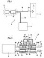
Fig. 1 : eine schematische Darstellung einer erfindungsgemäßen Vorrichtung zur Zufuhr eines Reduktionsmittels in Form eines Harnstoff-Wasser-Gemischs in einen Abgasstrang einer Verbrennungskraftmaschine; -
Fig. 2 : eine vergrößerte und teilweise geschnittene Darstellung des Ausschnitts II inFig. 1 . - Die als Ganzes in
Fig. 1 dargestellte Vorrichtung 2 dient zur Zufuhr eines Reduktionsmittels in ein in Richtung des Pfeils A vom Abgas eines Dieselmotors (nicht dargestellt) durchströmtes Abgasrohr 4. Das zugeführte Reduktionsmittel ist bevorzugt ein Harnstoff-Wasser-Gemisch (AdBlue), jedoch können auch andere Reduktionsmittel verwendet werden, insbesondere flüssige Reduktionsmittel. Die Vorrichtung 2 besteht im Wesentlichen aus einem Vorratsbehälter 6 für das Reduktionsmittel, einer herkömmlichen kontinuierlich arbeitenden Förderpumpe 8 für ein flüssiges Reduktionsmittel, wie ein Harnstoff-Wasser-Gemisch, deren Saugseite durch eine Saugleitung 10 mit dem Vorratsbehälter 6 verbunden ist und deren Druckseite durch eine Druckleitung 12 mit einer am Abgasrohr 4 angebrachten Einspritzdüse 14 verbunden ist, sowie einer Zumesseinheit 16 zur zeitweiligen Zumessung des von der Förderpumpe 8 geförderten Reduktionsmittels durch die Einspritzdüse 14 in das Abgasrohr 4. - Bei der Einspritzdüse 14, die das Reduktionsmittel zur besseren Durchmischung mit dem Abgas als Sprühkegel in das Abgasrohr 4 eindüst, wie in
Fig. 1 schematisch durch Pfeile B dargestellt, handelt es sich um eine druckgesteuerte Düse, die sich öffnet, wenn der Druck in der Druckleitung 12 vor der Düse 14 einen voreingestellten Öffnungsdruck der Düse 14 übersteigt. Solange jedoch der Druck in der Druckleitung 12 vor der Düse 14 unter dem Öffnungsdruck der Düse 14 liegt, bleibt diese geschlossen. - Wie am besten in
Fig. 2 dargestellt, verläuft sowohl die von der Förderpumpe 8 zur Einspritzdüse 14 führende Druckleitung 12 als auch die vom Vorratsbehälter 6 zur Förderpumpe 8 führende Saugleitung 12 durch die Zumesseinheit 16, wobei innerhalb der Zumesseinheit 16 angeordnete Leitungsabschnitte 18, 20 der Druckleitung 12 und der Saugleitung 10 zweckmäßig parallel zueinander ausgerichtet sind. Diese Leitungsabschnitte 18, 20 sind innerhalb der Zumesseinheit 16 durch einen Rückströmkanal 22 verbunden, der mit Hilfe eines Magnetventils 24 der Zumesseinheit 16 wahlweise geöffnet oder geschlossen werden kann. - Das Magnetventil 24 umfasst ein Gehäuse 26, eine in einem Spulenraum 28 des Gehäuses 26 untergebrachte, durch Stromzuführungen (nicht dargestellt) mit Strom beaufschlagbare Spule 30, einen von der Spule 30 umgebenen und entlang einer Längsachse L der Spule 30 beweglichen Magnetanker 32, ein starr mit dem Magnetanker 32 verbundenes Ventilglied 34 in Form einer Ventilnadel, sowie eine Schraubendruckfeder 36, die zwischen dem Gehäuse 26 und dem vom Ventilglied 34 abgewandten Stirnende des Magnetankers 32 angeordnet ist.
- In
Fig. 2 ist zur Vereinfachung der Zeichnung die Druckleitung 12 oberhalb von der Saugleitung 10 und das Magnetventil 24 oberhalb von der Druckleitung dargestellt, während in der Praxis vorzugsweise die Druckleitung 12, die Saugleitung 10 und der Rückströmkanal 22 in einer Ebene nebeneinander liegen und das Magnetventil 24 außerhalb dieser Ebene oberhalb oder unterhalb des Rückströmkanals 22 angeordnet ist. - In stromlosem Zustand der Spule 30 drückt die Druckfeder 36 das Ventilglied 34 gegen einen Ventilsitz 38 im Rückströmkanal 22, um diesen letzteren zu verschließen, während eine Stromzufuhr zur Spule 30 bewirkt, dass der Magnetanker 32 entgegen der Kraft der Druckfeder 36 in Richtung der Längsachse L der Spule 30 verschoben und dadurch das Ventilglied 34 unter Öffnen des Rückströmkanals 22 vom Ventilsitz 38 abgehoben wird.
- Bei geöffnetem Rückströmkanal 22 fördert die Förderpumpe 8 aus dem Vorratsbehälter angesaugtes Reduktionsmittel im Kreislauf durch einen die Druckseite der Förderpumpe 8 mit dem Rückströmkanal 22 in der Zumesseinheit 16 verbindenden Leitungsabschnitt 40 der Druckleitung 12, den Rückströmkanal 22, sowie einen den Rückströmkanal 22 mit der Saugseite der Förderpumpe verbindenden Leitungsabschnitt 42 der Saugleitung 10, so dass sich in dem an die Zumesseinheit 16 anschließenden, zur Einspritzdüse 14 führenden Leitungsabschnitt 44 der Druckleitung 12 kein Druck aufbauen kann. Somit bleibt die Einspritzdüse 14 geschlossen, und es wird kein Reduktionsmittel in das Abgasrohr 4 zugeführt. Sobald von einem Steuergerät (nicht dargestellt) des Motors eine Zufuhr von Reduktionsmittel in das Abgasrohr 4 angefordert wird, wird die Stromzufuhr zur Spule 30 des Magnetventils 24 unterbrochen, woraufhin die Druckfeder 36 das Ventilglied 34 gegen den Ventilsitz 38 im Rückströmkanal 22 drückt und diesen verschließt, wie in
Fig. 2 dargestellt. Wenn die Förderpumpe 8 bei geschlossenem Rückströmkanal 22 Reduktionsmittel aus dem Vorratsbehälter 6 in die Druckleitung 12 fördert, wie durch die Pfeile C und D inFig. 2 dargestellt, baut sich in der Druckleitung 12 ein Druck auf, der beim Überschreiten des Öffnungsdrucks der Einspritzdüse 14 zu einer Zufuhr von Reduktionsmittel in das Abgasrohr 4 führt. - Die in das Abgasrohr 4 zugeführte Menge des Reduktionsmittels ergibt sich aus der Leistung der Förderpumpe 8, der Kennlinie der Einspritzdüse 14 sowie der Verschlussdauer des Rückströmkanals 22 und kann daher durch Veränderung des zuletzt genannten Parameters gesteuert werden.
- Wenn zwischen der Förderpumpe 8 und der Einspritzdüse 14 ein zusätzlicher Druckregler (nicht dargestellt) vorgesehen ist, ergibt sich die in das Abgasrohr 4 zugeführte Menge des Reduktionsmittels aus dem am Druckregler eingestellten Druck und der Verschlussdauer des Rückströmkanals 22, so dass zur Steuerung der in das Abgasrohr 4 zugeführten Menge des Reduktionsmittels ebenfalls die Verschlussdauer des Rückströmkanals 22 verändert werden kann.
- Da das Magnetventil 24 bzw. Komponenten des Magnetventils 24, wie die Spule 30, die Stromzuleitungen zur Spule 30 innerhalb des Gehäuses 26, sowie ggf. auch der Magnetanker 32 in der Regel chemisch nicht gegen Reduktionsmittel bzw. deren Bestandteile oder Zersetzungsprodukte beständig sind, ist eine vom Ventilglied 34 durchsetzte Stufenbohrung 46 zwischen dem Magnetventil 24 und dem Ventilsitz 38 des Rückströmkanals 22 durch eine elastisch verformbare Membran 48 flüssigkeits- und gasdicht verschlossen, um ein Eindringen von Reduktionsmittel oder Bestandteilen bzw. Zersetzungsprodukten desselben aus dem Rückströmkanal 22 in den Spulenraum 28 des Magnetventils 24 zu verhindern.
- Dazu ist die ringförmige Membran 48 mit ihrem inneren Umfangsrand flüssigkeits- und gasdicht in eine umlaufende Nut im Umfang des Ventilglieds 34 eingebettet, während ihr äußerer Umfangrand flüssigkeits- und gasdicht zwischen einer Ringschulter der Stufenbohrung 46 und einer teilweise in die Stufenbohrung 46 ragenden Spulenhalterung 50 des Magnetventils 24 festgeklemmt ist. Die bei geschlossenem Rückströmkanal 22 unverformte Membran 48 wird elastisch verformt, wenn der Magnetanker 32 durch Stromzufuhr zur Spule 30 entgegen der Kraft der Feder 36 in Richtung der Längsachse L der Spule 30 verlagert und dabei das Ventilglied 34 vom Ventilsitz 38 abgehoben wird. Dabei wird jedoch der Ringspalt zwischen dem Ventilglied 34 und der Wand der Stufenbohrung 46 in jeder Ventilstellung des Ventilglieds 34 durch die Membran 48 hermetisch verschlossen.
- Während die Förderpumpe 8, die Druckleitung 12, die Saugleitung 10, der Vorratsbehälter 6 und ein ggf. zwischen dem Vorratsbehälter 6 und der Förderpumpe 8 angeordneter Filter (nicht dargestellt) in bekannter Weise so ausgebildet sind, dass sie im Falle eines Gefrierens des in ihnen enthaltenen flüssigen Reduktionsmittels gegen den dadurch bewirkten Eisdruck beständig sind, wird eine Eisdruckbeständigkeit der in
Fig. 2 dargestellten Zumesseinheit 16 dadurch erreicht, dass die durch die Zumesseinheit 16 verlaufenden Leitungsabschnitte 18 bzw. 20 der Druckleitung 12 und der Saugleitung 10 auf einem Teil ihrer Länge von röhrenförmigen Kompressionskörpern 52 umgeben sind. Die Kompressionskörper 52 sind elastisch verformbar, so dass sie bei einer Volumenvergrößerung des in der Zumesseinheit 16 enthaltenen flüssigen Reduktionsmittels infolge seines Gefrierens etwas zusammengedrückt werden und beim Auftauen des Reduktionsmittels wieder ihre ursprüngliche Form annehmen. - Da mit einer solchen Zumesseinheit 16 sämtliche Komponenten der Vorrichtung 2 eisdruckfest ausgebildet werden können, kann auf eine aufwändige Entleerung der Leitungen 10, 12 verzichtet werden. Außerdem werden Fehldosierungen vermieden, die sich infolge einer unvollständigen Entleerung der Leitungen 10, 12 ergeben können, da die in den Leitungen 10, 12 verbliebenen Restmengen des flüssigen Reduktionsmittels beim Entlüften der Leitungen 10, 12 zu ungewollten Fehlermengen und damit zu Abweichungen in der Bilanz des in das Abgasrohr 4 zugeführten Reduktionsmittels und folglich auch der gewünschten Dosierstrategie führen können.
- Das für die Zumesseinheit 16 beschriebene Prinzip wird auch in der Einspritzdüse 14 angewandt, um diese eisdruckfest zu machen, indem innerhalb der Einspritzdüse 14 zumindest ein Teil der Druckleitung 12 von einem röhrenförmigen Kompressionskörper (nicht dargestellt) umgeben ist.
Claims (8)
- Vorrichtung zur Zufuhr eines Reduktionsmittels in einen Abgasstrang einer Verbrennungskraftmaschine,- mit einer Förderpumpe zur Förderung des Reduktionsmittels aus einem Vorratsbehälter in den Abgasstrang.- wobei eine zwischen der Förderpumpe (8) und dem Abgasstrang (4) angeordnete Zumesseinrichtung (16) vorgesehen ist, die von der Förderpumpe (8) kontinuierlich gefördertes Reduktionsmittel zeitweilig in den Abgasstrang (4) zuführen kann, wobei die Zumesseinrichtung (16) eine Druckseite der Förderpumpe (8) wahlweise mit einer Saugseite der Förderpumpe (8) verbindet oder von der Saugseite trennt,- ein Steuergerät vorgesehen ist zur Ansteuerung der Zumesseinrichtung,- zwischen der Zumesseinrichtung (16) und dem Abgasstrang (4) eine Einspritzdüse (14) zum Eindüsen des Reduktionsmittels in den Abgasstrang (4) angeordnet ist, dadurch gekennzeichnet, dass- das Steuergerät eingerichtet ist zu einer derartigen Ansteuerung der Zumesseinrichtung, dass im Falle einer erforderlichen Zufuhr von Reduktionsmittel in den Abgasstrang die Druckseite von der Saugseite getrennt wird, so dass der Druck des zur Einspritzdüse (14) zugeführten Reduktionsmittels zu einer Zufuhr von Reduktionsmittel in den Abgasstrang (4) führt, wobei- die Zumesseinrichtung (16) entlang von einer Druckleitung (12) zwischen der Förderpumpe (8) und der Einspritzdüse (14) sowie entlang von einer Saugleitung (10) zwischen der Förderpumpe (8) und dem Vorratsbehälter (8) angeordnet ist, und wobei die Zumesseinrichtung (16) die Druckleitung (12) und die Saugleitung (10) wahlweise miteinander verbindet oder voneinander trennt.
- Vorrichtung nach Anspruch 1, dadurch gekennzeichnet, dass die Zumesseinrichtung (16) einen die Druckleitung (12) und die Saugleitung (10) verbindenden Rückströmkanal (22) und ein steuerbares Ventil (24) zum Verschließen bzw. Öffnen des Rückströmkanals (22) umfasst.
- Vorrichtung nach Anspruch 2, dadurch gekennzeichnet, dass das Ventil ein Magnetventil (24) ist und ein durch die Kraft einer Feder (36) beaufschlagte Ventilglied (34) aufweist, das den Rückströmkanal (22) in stromlosem Zustand des Magnetventils (24) verschließt.
- Vorrichtung nach Anspruch 3, gekennzeichnet durch eine elastisch verformbare Membran (48), die eine vom Ventilglied (34) durchsetzte Öffnung (46) zwischen dem Magnetventil (24) und dem Rückströmkanal (22) um das Ventilglied (34) herum hermetisch verschließ.
- Vorrichtung nach Anspruch 4, dadurch gekennzeichnet, dass die Membran (48) ringförmig ist, wobei sie entlang ihres inneren Umfangs flüssigkeitsdicht mit dem Ventilglied (34) und entlang ihres äußeren Umfangs flüssigkeitsdicht mit einer Begrenzungswand der Öffnung (46) verbunden ist.
- Vorrichtung nach einem der vorangehenden Ansprüche, dadurch gekennzeichnet, dass die Druckleitung (12) und die Saugleitung (10) innerhalb der Zumesseinrichtung (16) mindestens teilweise von elastisch verformbaren Kompressionskörpern (52) begrenzt werden.
- Vorrichtung nach einem der vorangehenden Ansprüche, dadurch gekennzeichnet, dass die Zumesseinrichtung (16) ein von der Förderpumpe (8) getrenntes Bauteil ist.
- Vorrichtung nach einem der vorhergehenden Ansprüche, dadurch gekennzeichnet, dass die Einspritzdüse (14) mindestens einen elastisch verformbaren Kompressionskörper umfasst, der eine Leitung zur Zufuhr des Reduktionsmittels in den Abgasstrang (4) innerhalb der Einspritzdüse (14) mindestens abschnittsweise umgibt.
Applications Claiming Priority (2)
| Application Number | Priority Date | Filing Date | Title |
|---|---|---|---|
| DE200610019051 DE102006019051A1 (de) | 2006-04-25 | 2006-04-25 | Vorrichtung zur Zufuhr eines Reduktionsmittels in einen Abgasstrang einer Verbrennungskraftmaschine |
| PCT/EP2007/052108 WO2007122035A1 (de) | 2006-04-25 | 2007-03-07 | Vorrichtung zur zufuhr eines reduktionsmittels in einen abgasstrang einer verbrennungskraftmaschine |
Publications (2)
| Publication Number | Publication Date |
|---|---|
| EP2013456A1 EP2013456A1 (de) | 2009-01-14 |
| EP2013456B1 true EP2013456B1 (de) | 2010-10-13 |
Family
ID=38069258
Family Applications (1)
| Application Number | Title | Priority Date | Filing Date |
|---|---|---|---|
| EP20070726666 Ceased EP2013456B1 (de) | 2006-04-25 | 2007-03-07 | Vorrichtung zur zufuhr eines reduktionsmittels in einen abgasstrang einer verbrennungskraftmaschine |
Country Status (6)
| Country | Link |
|---|---|
| US (1) | US8122709B2 (de) |
| EP (1) | EP2013456B1 (de) |
| JP (1) | JP2009534580A (de) |
| CN (1) | CN101421494B (de) |
| DE (2) | DE102006019051A1 (de) |
| WO (1) | WO2007122035A1 (de) |
Families Citing this family (15)
| Publication number | Priority date | Publication date | Assignee | Title |
|---|---|---|---|---|
| DE102008010106A1 (de) * | 2008-02-20 | 2009-08-27 | Robert Bosch Gmbh | Dosiersystem für Abgasnachbehandlung |
| FR2954403B1 (fr) * | 2009-12-22 | 2012-03-09 | Ti Automotive Fuel Systems Sas | Dispositif d'injection d'additifs aqueux dans une ligne d'echappement de vehicule automobile |
| DE102010013695A1 (de) | 2010-04-01 | 2011-10-06 | Emitec Gesellschaft Für Emissionstechnologie Mbh | Verfahren zum Betrieb einer Fördereinheit für ein Reduktionsmittel |
| DE102010038394A1 (de) * | 2010-07-26 | 2012-01-26 | Robert Bosch Gmbh | Verfahren zur Dosierung eines Reagenzmittels in einen Abgaskanal und Vorrichtung zur Durchführung des Verfahrens |
| DE102010052600A1 (de) * | 2010-11-25 | 2012-05-31 | Daimler Ag | Pumpanordnung zum Fördern einer Reduktionsmittellösung für die Abgasnachbehandlung und Verfahren zum Betreiben einer Pumpanordnung |
| DE102012019951B4 (de) * | 2012-10-11 | 2025-08-14 | Man Energy Solutions Se | Abgasnachbehandlungssystem für eine Brennkraftmaschine |
| CN103147828B (zh) * | 2013-03-26 | 2016-08-17 | 凯龙高科技股份有限公司 | 用于尿素泵的气液单向混合装置 |
| DE112014006732B4 (de) | 2014-06-11 | 2025-07-17 | Tenneco Automotive Operating Company Inc. | Abgasnachbehandlungssystem |
| US10202883B2 (en) | 2014-11-21 | 2019-02-12 | Tenneco (Suzhou) Emission System Co., Ltd. | Common rail assembly, urea injection system and application thereof |
| CN105673171B (zh) | 2014-11-21 | 2019-05-24 | 天纳克(苏州)排放系统有限公司 | 尾气后处理组件 |
| CN105673154B (zh) | 2014-11-21 | 2019-11-08 | 天纳克(苏州)排放系统有限公司 | 共轨、该共轨的应用、尿素喷射系统及其控制方法 |
| JP6663680B2 (ja) * | 2015-10-20 | 2020-03-13 | ボッシュ株式会社 | 還元剤噴射装置の制御装置 |
| DE102015118147A1 (de) | 2015-10-23 | 2017-04-27 | Eberspächer Exhaust Technology GmbH & Co. KG | Vorrichtung und Verfahren zur Abgabe von Reaktionsmittel in den Abgasstrom einer Brennkraftmaschine |
| CN106194706B (zh) * | 2016-09-22 | 2018-09-28 | 凯龙高科技股份有限公司 | 一种带阻尼孔的压力开关 |
| CN114439578B (zh) * | 2020-10-30 | 2024-09-13 | 长城汽车股份有限公司 | 尿素喷嘴、尿素喷射系统和车辆 |
Family Cites Families (17)
| Publication number | Priority date | Publication date | Assignee | Title |
|---|---|---|---|---|
| US5526837A (en) * | 1994-12-01 | 1996-06-18 | Robertshaw Controls Company | Solenoid controlled one-way valve |
| JPH0932540A (ja) * | 1995-07-13 | 1997-02-04 | Hino Motors Ltd | ディーゼルエンジンの排ガス浄化装置 |
| US5709080A (en) * | 1996-03-15 | 1998-01-20 | Caterpillar Inc. | Leak detection method and apparatus for an exhaust purification system |
| DE19743302C1 (de) * | 1997-09-30 | 1999-02-04 | Siemens Ag | Verfahren und Vorrichtung zum Ausstoßen und Zumessen von elektrisch leitfähigem, flüssigem Reduktionsmittel |
| DE19806265C5 (de) * | 1998-02-16 | 2004-07-22 | Siemens Ag | Dosiersystem |
| US6526746B1 (en) * | 2000-08-02 | 2003-03-04 | Ford Global Technologies, Inc. | On-board reductant delivery assembly |
| DE10047531A1 (de) * | 2000-09-22 | 2002-04-18 | Bosch Gmbh Robert | Vorrichtung zur Dosierung eines Reduktionsmittels |
| US6792966B2 (en) * | 2000-10-03 | 2004-09-21 | Federal-Mogul World Wide, Inc. | Fuel transfer pump and control |
| US6543746B2 (en) * | 2001-02-21 | 2003-04-08 | Delphi Technologies, Inc. | Shaft leakage containment system for a gas control valve |
| EP1236499B1 (de) * | 2001-03-02 | 2004-05-19 | Haldor Topsoe A/S | SCR Verfahren und Vorrichtung zur Reduktion von NOx-Emissionen |
| DE10150518C1 (de) | 2001-10-12 | 2003-05-08 | Siemens Ag | Verfahren und Vorrichtung zur Abgasnachbehandlung bei einer Brennkraftmaschine |
| US6810661B2 (en) | 2002-08-09 | 2004-11-02 | Ford Global Technologies, Llc | Method and system for freeze protecting liquid NOx reductants for vehicle application |
| US20040093856A1 (en) | 2002-11-18 | 2004-05-20 | Dingle Philip J. G. | Apparatus and method for reductant dosing of an exhaust |
| DE102004030441A1 (de) | 2004-06-24 | 2006-01-12 | Robert Bosch Gmbh | Dosierventilanordnung sowie Verfahren zum Betreiben einer Dosierventilanordnung |
| DE102004050023A1 (de) * | 2004-10-13 | 2006-04-27 | L'orange Gmbh | Einrichtung zur dosierten Einspritzung eines Reduktionsmittels in den Abgastrakt einer Brennkraftmaschine |
| DE102005002318A1 (de) * | 2005-01-17 | 2006-07-27 | Robert Bosch Gmbh | Abgasnachbehandlungsverfahren und Vorrichtung hierzu |
| KR100788302B1 (ko) * | 2006-04-13 | 2007-12-27 | 주식회사 코벡엔지니어링 | 고속제상 히트펌프 |
-
2006
- 2006-04-25 DE DE200610019051 patent/DE102006019051A1/de not_active Withdrawn
-
2007
- 2007-03-07 DE DE200750005350 patent/DE502007005350D1/de active Active
- 2007-03-07 WO PCT/EP2007/052108 patent/WO2007122035A1/de not_active Ceased
- 2007-03-07 CN CN2007800127212A patent/CN101421494B/zh not_active Expired - Fee Related
- 2007-03-07 JP JP2009507006A patent/JP2009534580A/ja not_active Withdrawn
- 2007-03-07 EP EP20070726666 patent/EP2013456B1/de not_active Ceased
- 2007-03-07 US US12/298,046 patent/US8122709B2/en not_active Expired - Fee Related
Also Published As
| Publication number | Publication date |
|---|---|
| DE102006019051A1 (de) | 2007-10-31 |
| EP2013456A1 (de) | 2009-01-14 |
| DE502007005350D1 (de) | 2010-11-25 |
| WO2007122035A1 (de) | 2007-11-01 |
| JP2009534580A (ja) | 2009-09-24 |
| US8122709B2 (en) | 2012-02-28 |
| CN101421494A (zh) | 2009-04-29 |
| CN101421494B (zh) | 2011-04-06 |
| US20090064667A1 (en) | 2009-03-12 |
Similar Documents
| Publication | Publication Date | Title |
|---|---|---|
| EP2013456B1 (de) | Vorrichtung zur zufuhr eines reduktionsmittels in einen abgasstrang einer verbrennungskraftmaschine | |
| DE102009023325B4 (de) | Verfahren zur Adaption der Injektionsmittelzufuhr in einem Injektionssystem | |
| EP2504540B1 (de) | Verfahren zum betrieb einer fördervorrichtung für ein reduktionsmittel | |
| EP2791481B1 (de) | Dosieranordnung für ein flüssiges abgasnachbehandlungsmittel und dosierverfahren | |
| EP1435458A1 (de) | Dosierpumpenaggregat | |
| DE10035678A1 (de) | On-Board-System für die Zufuhr von Reduktionsmitteln | |
| EP2839154B1 (de) | Dosiervorrichtung | |
| DE10231216A1 (de) | Einrichtung zur Abgasnachbehandlung von Kraftfahrzeugen, insbesondere Dieselkraftfahrzeugen | |
| WO2011141278A1 (de) | Vorrichtung zur reduktion von schadstoffen im abgasstrom eines verbrennungsmotors | |
| DE102010029340A1 (de) | Verfahren zum Betreiben eines SCR-Katalysators | |
| EP2636862B1 (de) | Fördereinheit für ein flüssiges Additiv sowie Verfahren zum Betrieb dieser Fördereinheit | |
| EP2669484B1 (de) | Einspritzsystem, Abgasnachbehandlungseinrichtung | |
| DE102010031651A1 (de) | Dosiervorrichtung | |
| EP2288795B1 (de) | Scr-system mit mehreren tanks | |
| EP2693014B1 (de) | Reduktionsmitteldosiersystem mit Dosierkammer zur exakten Dosiermengeneinstellung | |
| EP2614229B1 (de) | Reduktionsmitteldosiersystem zur eindüsung eines reduktionsmittels in den abgasstrom eines verbrennungsmotors | |
| WO2012150103A1 (de) | Pumpvorrichtung für dosiersystem | |
| EP2662550B1 (de) | Reduktionsmitteldosiersystem mit automatischer Belüftung der Reduktionsmittelleitung | |
| WO2014060313A1 (de) | Reduktionsmittelzuführeinrichtung | |
| EP2864602B1 (de) | Dosiersystem zur eindüsung eines reduktionsmittels in eine abgasleitung einer brennkraftmaschine | |
| DE102006061734A1 (de) | Vorrichtung zum Dosieren eines Reduktionsmittels | |
| DE102012216283A1 (de) | Pumpe und Anordnung zur Abgasnachbehandlung mit Pumpe | |
| DE102008006837A1 (de) | Baugruppe mit Einspritzvorrichtung und Pumpe, insbesondere für eine Abgasanlage, und Verfahren zum Betreiben einer Einspritzvorrichtung | |
| WO2009071427A1 (de) | Vorrichtung zur kraftstoffeinspritzung bei einer brennkraftmaschine | |
| EP4368818A1 (de) | Dosiersystem mit dosierpumpe mit ausschiebender feder |
Legal Events
| Date | Code | Title | Description |
|---|---|---|---|
| PUAI | Public reference made under article 153(3) epc to a published international application that has entered the european phase |
Free format text: ORIGINAL CODE: 0009012 |
|
| 17P | Request for examination filed |
Effective date: 20081125 |
|
| AK | Designated contracting states |
Kind code of ref document: A1 Designated state(s): AT BE BG CH CY CZ DE DK EE ES FI FR GB GR HU IE IS IT LI LT LU LV MC MT NL PL PT RO SE SI SK TR |
|
| AX | Request for extension of the european patent |
Extension state: AL BA HR MK RS |
|
| 17Q | First examination report despatched |
Effective date: 20090316 |
|
| RBV | Designated contracting states (corrected) |
Designated state(s): DE FR |
|
| GRAP | Despatch of communication of intention to grant a patent |
Free format text: ORIGINAL CODE: EPIDOSNIGR1 |
|
| GRAS | Grant fee paid |
Free format text: ORIGINAL CODE: EPIDOSNIGR3 |
|
| GRAA | (expected) grant |
Free format text: ORIGINAL CODE: 0009210 |
|
| AK | Designated contracting states |
Kind code of ref document: B1 Designated state(s): DE FR |
|
| REF | Corresponds to: |
Ref document number: 502007005350 Country of ref document: DE Date of ref document: 20101125 Kind code of ref document: P |
|
| PLBE | No opposition filed within time limit |
Free format text: ORIGINAL CODE: 0009261 |
|
| STAA | Information on the status of an ep patent application or granted ep patent |
Free format text: STATUS: NO OPPOSITION FILED WITHIN TIME LIMIT |
|
| 26N | No opposition filed |
Effective date: 20110714 |
|
| REG | Reference to a national code |
Ref country code: DE Ref legal event code: R097 Ref document number: 502007005350 Country of ref document: DE Effective date: 20110714 |
|
| REG | Reference to a national code |
Ref country code: FR Ref legal event code: PLFP Year of fee payment: 10 |
|
| REG | Reference to a national code |
Ref country code: FR Ref legal event code: PLFP Year of fee payment: 11 |
|
| REG | Reference to a national code |
Ref country code: FR Ref legal event code: PLFP Year of fee payment: 12 |
|
| PGFP | Annual fee paid to national office [announced via postgrant information from national office to epo] |
Ref country code: DE Payment date: 20190520 Year of fee payment: 13 |
|
| PGFP | Annual fee paid to national office [announced via postgrant information from national office to epo] |
Ref country code: FR Payment date: 20200324 Year of fee payment: 14 |
|
| REG | Reference to a national code |
Ref country code: DE Ref legal event code: R119 Ref document number: 502007005350 Country of ref document: DE |
|
| PG25 | Lapsed in a contracting state [announced via postgrant information from national office to epo] |
Ref country code: DE Free format text: LAPSE BECAUSE OF NON-PAYMENT OF DUE FEES Effective date: 20201001 |
|
| PG25 | Lapsed in a contracting state [announced via postgrant information from national office to epo] |
Ref country code: FR Free format text: LAPSE BECAUSE OF NON-PAYMENT OF DUE FEES Effective date: 20210331 |