EP2013456B1 - Dispositif pour acheminer un agent reducteur dans une branche de gaz d'echappement d'un moteur a combustion interne - Google Patents
Dispositif pour acheminer un agent reducteur dans une branche de gaz d'echappement d'un moteur a combustion interne Download PDFInfo
- Publication number
- EP2013456B1 EP2013456B1 EP20070726666 EP07726666A EP2013456B1 EP 2013456 B1 EP2013456 B1 EP 2013456B1 EP 20070726666 EP20070726666 EP 20070726666 EP 07726666 A EP07726666 A EP 07726666A EP 2013456 B1 EP2013456 B1 EP 2013456B1
- Authority
- EP
- European Patent Office
- Prior art keywords
- reducing agent
- pressure
- line
- metering device
- feed pump
- Prior art date
- Legal status (The legal status is an assumption and is not a legal conclusion. Google has not performed a legal analysis and makes no representation as to the accuracy of the status listed.)
- Ceased
Links
Images
Classifications
-
- B—PERFORMING OPERATIONS; TRANSPORTING
- B01—PHYSICAL OR CHEMICAL PROCESSES OR APPARATUS IN GENERAL
- B01D—SEPARATION
- B01D53/00—Separation of gases or vapours; Recovering vapours of volatile solvents from gases; Chemical or biological purification of waste gases, e.g. engine exhaust gases, smoke, fumes, flue gases, aerosols
- B01D53/34—Chemical or biological purification of waste gases
- B01D53/92—Chemical or biological purification of waste gases of engine exhaust gases
- B01D53/94—Chemical or biological purification of waste gases of engine exhaust gases by catalytic processes
- B01D53/9404—Removing only nitrogen compounds
- B01D53/9409—Nitrogen oxides
- B01D53/9431—Processes characterised by a specific device
-
- B—PERFORMING OPERATIONS; TRANSPORTING
- B01—PHYSICAL OR CHEMICAL PROCESSES OR APPARATUS IN GENERAL
- B01D—SEPARATION
- B01D53/00—Separation of gases or vapours; Recovering vapours of volatile solvents from gases; Chemical or biological purification of waste gases, e.g. engine exhaust gases, smoke, fumes, flue gases, aerosols
- B01D53/34—Chemical or biological purification of waste gases
- B01D53/74—General processes for purification of waste gases; Apparatus or devices specially adapted therefor
- B01D53/86—Catalytic processes
- B01D53/90—Injecting reactants
-
- F—MECHANICAL ENGINEERING; LIGHTING; HEATING; WEAPONS; BLASTING
- F01—MACHINES OR ENGINES IN GENERAL; ENGINE PLANTS IN GENERAL; STEAM ENGINES
- F01N—GAS-FLOW SILENCERS OR EXHAUST APPARATUS FOR MACHINES OR ENGINES IN GENERAL; GAS-FLOW SILENCERS OR EXHAUST APPARATUS FOR INTERNAL-COMBUSTION ENGINES
- F01N3/00—Exhaust or silencing apparatus having means for purifying, rendering innocuous, or otherwise treating exhaust
- F01N3/08—Exhaust or silencing apparatus having means for purifying, rendering innocuous, or otherwise treating exhaust for rendering innocuous
- F01N3/10—Exhaust or silencing apparatus having means for purifying, rendering innocuous, or otherwise treating exhaust for rendering innocuous by thermal or catalytic conversion of noxious components of exhaust
- F01N3/18—Exhaust or silencing apparatus having means for purifying, rendering innocuous, or otherwise treating exhaust for rendering innocuous by thermal or catalytic conversion of noxious components of exhaust characterised by methods of operation; Control
- F01N3/20—Exhaust or silencing apparatus having means for purifying, rendering innocuous, or otherwise treating exhaust for rendering innocuous by thermal or catalytic conversion of noxious components of exhaust characterised by methods of operation; Control specially adapted for catalytic conversion
- F01N3/206—Adding periodically or continuously substances to exhaust gases for promoting purification, e.g. catalytic material in liquid form, NOx reducing agents
- F01N3/2066—Selective catalytic reduction [SCR]
-
- F—MECHANICAL ENGINEERING; LIGHTING; HEATING; WEAPONS; BLASTING
- F01—MACHINES OR ENGINES IN GENERAL; ENGINE PLANTS IN GENERAL; STEAM ENGINES
- F01N—GAS-FLOW SILENCERS OR EXHAUST APPARATUS FOR MACHINES OR ENGINES IN GENERAL; GAS-FLOW SILENCERS OR EXHAUST APPARATUS FOR INTERNAL-COMBUSTION ENGINES
- F01N3/00—Exhaust or silencing apparatus having means for purifying, rendering innocuous, or otherwise treating exhaust
- F01N3/08—Exhaust or silencing apparatus having means for purifying, rendering innocuous, or otherwise treating exhaust for rendering innocuous
- F01N3/10—Exhaust or silencing apparatus having means for purifying, rendering innocuous, or otherwise treating exhaust for rendering innocuous by thermal or catalytic conversion of noxious components of exhaust
- F01N3/18—Exhaust or silencing apparatus having means for purifying, rendering innocuous, or otherwise treating exhaust for rendering innocuous by thermal or catalytic conversion of noxious components of exhaust characterised by methods of operation; Control
- F01N3/20—Exhaust or silencing apparatus having means for purifying, rendering innocuous, or otherwise treating exhaust for rendering innocuous by thermal or catalytic conversion of noxious components of exhaust characterised by methods of operation; Control specially adapted for catalytic conversion
- F01N3/206—Adding periodically or continuously substances to exhaust gases for promoting purification, e.g. catalytic material in liquid form, NOx reducing agents
- F01N3/208—Control of selective catalytic reduction [SCR], e.g. by adjusting the dosing of reducing agent
-
- F—MECHANICAL ENGINEERING; LIGHTING; HEATING; WEAPONS; BLASTING
- F01—MACHINES OR ENGINES IN GENERAL; ENGINE PLANTS IN GENERAL; STEAM ENGINES
- F01N—GAS-FLOW SILENCERS OR EXHAUST APPARATUS FOR MACHINES OR ENGINES IN GENERAL; GAS-FLOW SILENCERS OR EXHAUST APPARATUS FOR INTERNAL-COMBUSTION ENGINES
- F01N9/00—Electrical control of exhaust gas treating apparatus
-
- B—PERFORMING OPERATIONS; TRANSPORTING
- B01—PHYSICAL OR CHEMICAL PROCESSES OR APPARATUS IN GENERAL
- B01D—SEPARATION
- B01D2251/00—Reactants
- B01D2251/20—Reductants
- B01D2251/206—Ammonium compounds
-
- F—MECHANICAL ENGINEERING; LIGHTING; HEATING; WEAPONS; BLASTING
- F01—MACHINES OR ENGINES IN GENERAL; ENGINE PLANTS IN GENERAL; STEAM ENGINES
- F01N—GAS-FLOW SILENCERS OR EXHAUST APPARATUS FOR MACHINES OR ENGINES IN GENERAL; GAS-FLOW SILENCERS OR EXHAUST APPARATUS FOR INTERNAL-COMBUSTION ENGINES
- F01N2610/00—Adding substances to exhaust gases
- F01N2610/02—Adding substances to exhaust gases the substance being ammonia or urea
-
- F—MECHANICAL ENGINEERING; LIGHTING; HEATING; WEAPONS; BLASTING
- F01—MACHINES OR ENGINES IN GENERAL; ENGINE PLANTS IN GENERAL; STEAM ENGINES
- F01N—GAS-FLOW SILENCERS OR EXHAUST APPARATUS FOR MACHINES OR ENGINES IN GENERAL; GAS-FLOW SILENCERS OR EXHAUST APPARATUS FOR INTERNAL-COMBUSTION ENGINES
- F01N2610/00—Adding substances to exhaust gases
- F01N2610/14—Arrangements for the supply of substances, e.g. conduits
- F01N2610/1433—Pumps
-
- F—MECHANICAL ENGINEERING; LIGHTING; HEATING; WEAPONS; BLASTING
- F01—MACHINES OR ENGINES IN GENERAL; ENGINE PLANTS IN GENERAL; STEAM ENGINES
- F01N—GAS-FLOW SILENCERS OR EXHAUST APPARATUS FOR MACHINES OR ENGINES IN GENERAL; GAS-FLOW SILENCERS OR EXHAUST APPARATUS FOR INTERNAL-COMBUSTION ENGINES
- F01N2610/00—Adding substances to exhaust gases
- F01N2610/14—Arrangements for the supply of substances, e.g. conduits
- F01N2610/1453—Sprayers or atomisers; Arrangement thereof in the exhaust apparatus
- F01N2610/146—Control thereof, e.g. control of injectors or injection valves
-
- F—MECHANICAL ENGINEERING; LIGHTING; HEATING; WEAPONS; BLASTING
- F01—MACHINES OR ENGINES IN GENERAL; ENGINE PLANTS IN GENERAL; STEAM ENGINES
- F01N—GAS-FLOW SILENCERS OR EXHAUST APPARATUS FOR MACHINES OR ENGINES IN GENERAL; GAS-FLOW SILENCERS OR EXHAUST APPARATUS FOR INTERNAL-COMBUSTION ENGINES
- F01N2610/00—Adding substances to exhaust gases
- F01N2610/14—Arrangements for the supply of substances, e.g. conduits
- F01N2610/1473—Overflow or return means for the substances, e.g. conduits or valves for the return path
-
- F—MECHANICAL ENGINEERING; LIGHTING; HEATING; WEAPONS; BLASTING
- F01—MACHINES OR ENGINES IN GENERAL; ENGINE PLANTS IN GENERAL; STEAM ENGINES
- F01N—GAS-FLOW SILENCERS OR EXHAUST APPARATUS FOR MACHINES OR ENGINES IN GENERAL; GAS-FLOW SILENCERS OR EXHAUST APPARATUS FOR INTERNAL-COMBUSTION ENGINES
- F01N2900/00—Details of electrical control or of the monitoring of the exhaust gas treating apparatus
- F01N2900/06—Parameters used for exhaust control or diagnosing
- F01N2900/18—Parameters used for exhaust control or diagnosing said parameters being related to the system for adding a substance into the exhaust
- F01N2900/1806—Properties of reducing agent or dosing system
- F01N2900/1808—Pressure
-
- Y—GENERAL TAGGING OF NEW TECHNOLOGICAL DEVELOPMENTS; GENERAL TAGGING OF CROSS-SECTIONAL TECHNOLOGIES SPANNING OVER SEVERAL SECTIONS OF THE IPC; TECHNICAL SUBJECTS COVERED BY FORMER USPC CROSS-REFERENCE ART COLLECTIONS [XRACs] AND DIGESTS
- Y02—TECHNOLOGIES OR APPLICATIONS FOR MITIGATION OR ADAPTATION AGAINST CLIMATE CHANGE
- Y02T—CLIMATE CHANGE MITIGATION TECHNOLOGIES RELATED TO TRANSPORTATION
- Y02T10/00—Road transport of goods or passengers
- Y02T10/10—Internal combustion engine [ICE] based vehicles
- Y02T10/12—Improving ICE efficiencies
-
- Y—GENERAL TAGGING OF NEW TECHNOLOGICAL DEVELOPMENTS; GENERAL TAGGING OF CROSS-SECTIONAL TECHNOLOGIES SPANNING OVER SEVERAL SECTIONS OF THE IPC; TECHNICAL SUBJECTS COVERED BY FORMER USPC CROSS-REFERENCE ART COLLECTIONS [XRACs] AND DIGESTS
- Y02—TECHNOLOGIES OR APPLICATIONS FOR MITIGATION OR ADAPTATION AGAINST CLIMATE CHANGE
- Y02T—CLIMATE CHANGE MITIGATION TECHNOLOGIES RELATED TO TRANSPORTATION
- Y02T10/00—Road transport of goods or passengers
- Y02T10/10—Internal combustion engine [ICE] based vehicles
- Y02T10/40—Engine management systems
-
- Y—GENERAL TAGGING OF NEW TECHNOLOGICAL DEVELOPMENTS; GENERAL TAGGING OF CROSS-SECTIONAL TECHNOLOGIES SPANNING OVER SEVERAL SECTIONS OF THE IPC; TECHNICAL SUBJECTS COVERED BY FORMER USPC CROSS-REFERENCE ART COLLECTIONS [XRACs] AND DIGESTS
- Y10—TECHNICAL SUBJECTS COVERED BY FORMER USPC
- Y10T—TECHNICAL SUBJECTS COVERED BY FORMER US CLASSIFICATION
- Y10T137/00—Fluid handling
- Y10T137/8593—Systems
- Y10T137/85978—With pump
- Y10T137/85986—Pumped fluid control
- Y10T137/86027—Electric
Definitions
- the invention relates to a device for supplying a reducing agent, in particular a urea-water mixture, in an exhaust line of an internal combustion engine.
- AdBlue urea-water solution commonly referred to as AdBlue is generally fed into the exhaust gas line in order to reduce the nitrogen oxide content in the exhaust gas of diesel engines.
- the urea of the injected solution is converted in the exhaust gas line to ammonia (NH 3 ), which reduces the nitrogen oxides (NO x ) contained in the exhaust gas in a downstream SCR catalyst to form molecular nitrogen (N 2 ) and water (H 2 O). Since the nitrogen oxides (NO x ) can be almost completely removed from the exhaust gas in this way, diesel engines can be operated with a relatively lean mixture, which in turn allows fuel-efficient operation of the engines.
- the use of other reducing agents is also conceivable.
- the supply is carried out either by means of a feed pump without Congressnzumessfunktion or by means of a metering pump.
- the first-mentioned feed pumps have over the metering pumps the advantage that they are not only chemically resistant to the urea or free ammonia in the urea-water mixture, but in the case of freezing the urea-water mixture can also withstand the ice pressure caused by its volume expansion without damage, which is not guaranteed in the latter metering pumps.
- the present invention seeks to improve a device of the type mentioned in that it is not only resistant to reducing agents or their components resistant to ice and water-containing reducing agents, but also allows Congressnzuflop.
- the reducing agent is conveyed by means of a reducing agent pump to a metering valve and injected into a mixing chamber, where it is mixed with air.
- the mixture is supplied from the mixing chamber under pressure via a mixture line to the exhaust gas of the Brennleraftmaschine.
- the invention proposes a device for supplying a reducing agent having the features of the preamble of claim 1, between the pump and the exhaust line to provide an additional metering device, which feeds the pump continuously fed reducing agent temporarily into the exhaust system and thus takes over the Congressnzumessfunktion ,
- This solution makes it possible on the one hand to use proven conventional feed pumps without Quiltnzumessfunktion not only inexpensive, but also against reducing agents, such as a urea-water mixture, resistant and resistant to ice pressure.
- the feed pump can work throughout the operating time of the internal combustion engine, which can be dispensed with a control of the pump, which not only leads to cost savings, but also ensures a lower susceptibility due to the more robust construction of such feed pumps.
- the feed pump can also be driven directly by the internal combustion engine.
- the reducing agent is injected by means of an injection nozzle in the exhaust line.
- the pressure of the reducing agent in front of the nozzle opening when this pressure exceeds a certain opening pressure, and closing when the pressure falls below the opening pressure.
- the metering device which according to the invention connects the pressure side of the pump with a suction side of the pump, if no reducing agent is to be fed into the exhaust line, and which separates the pressure side of the pump from the suction side, if for the purpose of supplying a reducing agent in the exhaust line pressure is to be built up in front of the nozzle.
- the pressure side of the pump is connected to the suction side of the pump, the latter promotes the reducing agent in the circuit. This means that sufficient pressure can not build up in front of the nozzle, which exceeds the opening pressure of the nozzle, and thus that the nozzle remains closed. If, on the other hand, the pressure side of the pump is separated from its suction side, the continuous pumping automatically builds up pressure exceeding the opening pressure of the nozzle in front of the nozzle so that it opens and provides a supply of reducing agent into the exhaust gas line.
- the metering device is arranged along a pressure line connecting the pump to the nozzle and along a suction line connecting the pump to the reservoir and comprising a return flow channel connecting the pressure line and the suction line, which can be opened or closed as required by a controllable valve.
- the valve is advantageously designed as a solenoid valve and has a valve member which is pressed by the force of a spring against a valve seat in the return flow passage in order to close it.
- the valve member is lifted off the valve seat to open the return flow channel.
- solenoid valves such as the coil and the power supply to the coil
- these components should not with the reducing agent, such as urea -Water mixture, or its components or decomposition products, such as ammonia, come into contact to prevent corrosion and consequent malfunction.
- an opening penetrated by the valve member between a coil space of the solenoid valve and the return flow around the valve member is hermetically sealed by an elastically deformable membrane.
- the pressure line and / or the suction line are at least partially surrounded by elastically deformable compression bodies within the metering unit , which are compressed in the caused by the freezing volume expansion of the reducing agent and thus provide a significant reduction in freezing pressure.
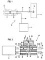
- the as a whole in Fig. 1 illustrated device 2 is used for supplying a reducing agent in an in the direction of arrow A from the exhaust of a diesel engine (not shown) through-flow exhaust pipe 4.
- the supplied reducing agent is preferably a urea-water mixture (AdBlue), but other reducing agents can be used, in particular, liquid reducing agents.
- the device 2 consists essentially of a reservoir 6 for the reducing agent, a conventional continuously operating feed pump 8 for a liquid reducing agent, such as a urea-water mixture whose suction side is connected by a suction line 10 to the reservoir 6 and the pressure side by a Pressure line 12 is connected to an attached to the exhaust pipe 4 injection nozzle 14, and a metering unit 16 for temporarily metering the funded by the feed pump 8 reducing agent through the injection nozzle 14 into the exhaust pipe.
- a liquid reducing agent such as a urea-water mixture
- the injection nozzle 14 which injects the reducing agent for better mixing with the exhaust gas as a spray cone in the exhaust pipe 4, as in Fig. 1 schematically represented by arrows B, it is a pressure-controlled nozzle, which opens when the pressure in the pressure line 12 in front of the nozzle 14 exceeds a preset opening pressure of the nozzle 14. However, as long as the pressure in the pressure line 12 in front of the nozzle 14 is below the opening pressure of the nozzle 14, this remains closed.
- both the leading from the feed pump 8 to the injector 14 pressure line 12 and the leading from the reservoir 6 to the feed pump 8 runs Suction line 12 through the metering unit 16, wherein arranged within the metering unit 16 line sections 18, 20 of the pressure line 12 and the suction line 10 are suitably aligned parallel to each other. These line sections 18, 20 are connected within the metering unit 16 through a return flow channel 22 which can be selectively opened or closed by means of a solenoid valve 24 of the metering unit 16.
- the solenoid valve 24 includes a housing 26, a coil 30 housed in a coil space 28 of the housing 26, by power supply lines (not shown) can be energized coil 30, one of the coil 30 and along a longitudinal axis L of the coil 30 movable magnet armature 32, a rigid with the armature 32 connected valve member 34 in the form of a valve needle, and a helical compression spring 36 which is disposed between the housing 26 and the end remote from the valve member 34 front end of the armature 32.
- the pressure line 12 is shown above the suction line 10 and the solenoid valve 24 above the pressure line, while in practice preferably the pressure line 12, the suction line 10 and the return flow 22 in a plane next to each other and the solenoid valve 24 outside this Level above or below the return flow 22 is arranged.
- the compression spring 36 presses the valve member 34 against a valve seat 38 in the return flow 22 to close the latter, while a current supply to the coil 30 causes the armature 32 against the force of the compression spring 36 in the direction of the longitudinal axis L. the coil 30 is displaced and thereby the valve member 34 is lifted by opening the return flow channel 22 from the valve seat 38.
- the feed pump 8 delivers reductant sucked from the reservoir into the circuit through a line section 40 of the pressure line 12 connecting the pressure side of the feed pump 8 to the return flow channel 22 in the metering unit 16, the return flow channel 22 and the return flow channel 22 to the suction side Feed line connecting line section 42 of the suction line 10, so that in the adjoining the metering unit 16, leading to the injection nozzle 14 line section 44 of the pressure line 12 can not build up pressure.
- the injection nozzle 14 remains closed and no reducing agent is supplied into the exhaust pipe 4.
- the amount of reducing agent supplied into the exhaust pipe 4 results from the power of the feed pump 8, the characteristic curve of the injection nozzle 14 and the closing duration of the return flow channel 22 and can therefore be controlled by changing the latter parameter.
- the amount of reducing agent fed into the exhaust pipe 4 results from the pressure set on the pressure regulator and the closing duration of the return flow channel 22, so that the control of the in the Exhaust pipe 4 supplied amount of the reducing agent also the closing duration of the return flow 22 can be changed.
- the solenoid valve 24 or components of the solenoid valve 24, such as the coil 30, the power supply lines to the coil 30 within the housing 26, and possibly also the armature 32 are usually chemically resistant to reducing agents or their components or decomposition products, is a stepped bore 46 penetrated by the valve member 34 between the solenoid valve 24 and the valve seat 38 of remindströmkanals 22 liquid-tight and gas-tight by an elastically deformable membrane 48 to penetration of reducing agent or components or decomposition products thereof from the return flow 22 into the coil space 28 of the Solenoid valve 24 to prevent.
- the annular membrane 48 with its inner peripheral edge liquid and gas-tight embedded in a circumferential groove in the circumference of the valve member 34, while its outer peripheral edge liquid and gas tight between an annular shoulder of the stepped bore 46 and a partially projecting into the stepped bore 46 coil holder 50 of Solenoid valve 24 is clamped.
- the undeformed at 48 closed return flow membrane 48 is elastically deformed when the armature 32 displaced by power to the coil 30 against the force of the spring 36 in the direction of the longitudinal axis L of the coil 30 while the valve member 34 is lifted from the valve seat 38.
- the annular gap between the valve member 34 and the wall of the stepped bore 46 in each valve position of the valve member 34 is hermetically sealed by the membrane 48.
- an ice pressure resistance of in Fig. 2 shown metering unit 16 achieved in that the extending through the metering unit 16 line sections 18 and 20 of the pressure line 12 and the suction line 10 are surrounded on part of their length of tubular compression bodies 52.
- the compression bodies 52 are elastically deformable, so that they are slightly compressed in an increase in volume of the liquid reducing agent contained in the metering unit 16 due to its freezing and assume their original shape during thawing of the reducing agent.
- the principle described for the metering unit 16 is also applied in the injection nozzle 14 to make them ice-tight by at least a portion of the pressure line 12 is surrounded by a tubular compression body (not shown) within the injection nozzle 14.
Landscapes
- Engineering & Computer Science (AREA)
- Chemical & Material Sciences (AREA)
- Chemical Kinetics & Catalysis (AREA)
- Combustion & Propulsion (AREA)
- Health & Medical Sciences (AREA)
- Mechanical Engineering (AREA)
- General Engineering & Computer Science (AREA)
- Environmental & Geological Engineering (AREA)
- Toxicology (AREA)
- Biomedical Technology (AREA)
- Analytical Chemistry (AREA)
- General Chemical & Material Sciences (AREA)
- Oil, Petroleum & Natural Gas (AREA)
- Exhaust Gas After Treatment (AREA)
Abstract
Claims (8)
- Dispositif pour acheminer un agent réducteur dans une branche de gaz d'échappement d'un moteur à combustion interne,- comprenant une pompe de refoulement pour refouler l'agent réducteur hors d'un réservoir dans la branche de gaz d'échappement,- un dispositif de dosage (16) disposé entre la pompe de refoulement (8) et la branche de gaz d'échappement (4) étant prévu, lequel peut acheminer l'agent réducteur refoulé en continu par la pompe de refoulement (8) temporairement dans la branche de gaz d'échappement (4),- le dispositif de dosage (16) reliant un côté pression de la pompe de refoulement (8) de manière sélective à un côté aspiration de la pompe de refoulement (8) ou le séparant du côté aspiration,- un appareil de commande étant prévu pour commander le dispositif de dosage,- entre le dispositif de dosage (16) et la branche de gaz d'échappement (4) étant disposée une buse d'injection (14) pour injecter l'agent réducteur dans la branche de gaz d'échappement (4),caractérisé en ce que- l'appareil de commande est prévu pour effectuer une commande du dispositif de dosage de telle sorte que dans le cas d'une alimentation requise en agent réducteur dans la branche de gaz d'échappement, le côté pression soit séparé du côté aspiration, de sorte que la pression de l'agent réducteur acheminé à la buse d'injection (14) conduise à une alimentation en agent réducteur dans la branche de gaz d'échappement (4),- le dispositif de dosage (16) étant disposé le long d'une conduite de pression (12) entre la pompe de refoulement (8) et la buse d'injection (14) et le long d'une conduite d'aspiration (10) entre la pompe de refoulement (8) et le réservoir (8), et le dispositif de dosage (16) reliant la conduite de pression (12) et la conduite d'aspiration (10) de manière sélective l'une à l'autre ou les séparant l'une de l'autre.
- Dispositif selon la revendication 1, caractérisé en ce que le dispositif de dosage (16) comprend un canal de reflux (22) reliant la conduite de pression (12) et la conduite d'aspiration (10) et une soupape commandable (24) pour fermer ou ouvrir le canal de reflux (22).
- Dispositif selon la revendication 2, caractérisé en ce que la soupape est une électrovanne (24) et présente un organe de soupape (34) sollicité par la force d'un ressort (36), qui ferme le canal de reflux (22) dans l'état non alimenté en courant de l'électrovanne (24).
- Dispositif selon la revendication 3, caractérisé par une membrane déformable élastiquement (48), qui ferme une ouverture (46) traversée par l'organe de soupape (34) entre l'électrovanne (24) et le canal de reflux (22) de manière hermétique tout autour de l'organe de soupape (34).
- Dispositif selon la revendication 4, caractérisé en ce que la membrane (48) est annulaire, et elle est connectée le long de sa périphérie intérieure de manière étanche aux fluides à l'organe de soupape (34) et le long de sa périphérie extérieure de manière étanche aux fluides à une paroi de limitation de l'ouverture (46).
- Dispositif selon l'une quelconque des revendications précédentes, caractérisé en ce que la conduite de pression (12) et la conduite d'aspiration (10) sont limitées à l'intérieur du dispositif de dosage (16) au moins en partie par des corps de compression déformables élastiquement (52).
- Dispositif selon l'une quelconque des revendications précédentes, caractérisé en ce que le dispositif de dosage (16) est un composant séparé de la pompe de refoulement (8).
- Dispositif selon l'une quelconque des revendications précédentes, caractérisé en ce que la buse d'injection (14) comprend au moins un corps de compression déformable élastiquement, qui entoure au moins en partie une conduite pour l'alimentation en agent réducteur dans la branche de gaz d'échappement (4) à l'intérieur de la buse d'injection (14).
Applications Claiming Priority (2)
| Application Number | Priority Date | Filing Date | Title |
|---|---|---|---|
| DE200610019051 DE102006019051A1 (de) | 2006-04-25 | 2006-04-25 | Vorrichtung zur Zufuhr eines Reduktionsmittels in einen Abgasstrang einer Verbrennungskraftmaschine |
| PCT/EP2007/052108 WO2007122035A1 (fr) | 2006-04-25 | 2007-03-07 | Dispositif pour acheminer un agent réducteur dans une branche de gaz d'échappement d'un moteur à combustion interne |
Publications (2)
| Publication Number | Publication Date |
|---|---|
| EP2013456A1 EP2013456A1 (fr) | 2009-01-14 |
| EP2013456B1 true EP2013456B1 (fr) | 2010-10-13 |
Family
ID=38069258
Family Applications (1)
| Application Number | Title | Priority Date | Filing Date |
|---|---|---|---|
| EP20070726666 Ceased EP2013456B1 (fr) | 2006-04-25 | 2007-03-07 | Dispositif pour acheminer un agent reducteur dans une branche de gaz d'echappement d'un moteur a combustion interne |
Country Status (6)
| Country | Link |
|---|---|
| US (1) | US8122709B2 (fr) |
| EP (1) | EP2013456B1 (fr) |
| JP (1) | JP2009534580A (fr) |
| CN (1) | CN101421494B (fr) |
| DE (2) | DE102006019051A1 (fr) |
| WO (1) | WO2007122035A1 (fr) |
Families Citing this family (15)
| Publication number | Priority date | Publication date | Assignee | Title |
|---|---|---|---|---|
| DE102008010106A1 (de) * | 2008-02-20 | 2009-08-27 | Robert Bosch Gmbh | Dosiersystem für Abgasnachbehandlung |
| FR2954403B1 (fr) * | 2009-12-22 | 2012-03-09 | Ti Automotive Fuel Systems Sas | Dispositif d'injection d'additifs aqueux dans une ligne d'echappement de vehicule automobile |
| DE102010013695A1 (de) * | 2010-04-01 | 2011-10-06 | Emitec Gesellschaft Für Emissionstechnologie Mbh | Verfahren zum Betrieb einer Fördereinheit für ein Reduktionsmittel |
| DE102010038394A1 (de) * | 2010-07-26 | 2012-01-26 | Robert Bosch Gmbh | Verfahren zur Dosierung eines Reagenzmittels in einen Abgaskanal und Vorrichtung zur Durchführung des Verfahrens |
| DE102010052600A1 (de) * | 2010-11-25 | 2012-05-31 | Daimler Ag | Pumpanordnung zum Fördern einer Reduktionsmittellösung für die Abgasnachbehandlung und Verfahren zum Betreiben einer Pumpanordnung |
| DE102012019951B4 (de) * | 2012-10-11 | 2025-08-14 | Man Energy Solutions Se | Abgasnachbehandlungssystem für eine Brennkraftmaschine |
| CN103147828B (zh) * | 2013-03-26 | 2016-08-17 | 凯龙高科技股份有限公司 | 用于尿素泵的气液单向混合装置 |
| US10180096B2 (en) | 2014-06-11 | 2019-01-15 | Tenneco Automotive Operating Company Inc. | Fluid delivery system with line pressure control valve |
| CN105673154B (zh) | 2014-11-21 | 2019-11-08 | 天纳克(苏州)排放系统有限公司 | 共轨、该共轨的应用、尿素喷射系统及其控制方法 |
| CN105673171B (zh) | 2014-11-21 | 2019-05-24 | 天纳克(苏州)排放系统有限公司 | 尾气后处理组件 |
| WO2016078538A1 (fr) | 2014-11-21 | 2016-05-26 | 天纳克(苏州)排放系统有限公司 | Ensemble rail commun, système d'injection d'urée et son application |
| JP6663680B2 (ja) * | 2015-10-20 | 2020-03-13 | ボッシュ株式会社 | 還元剤噴射装置の制御装置 |
| DE102015118147A1 (de) | 2015-10-23 | 2017-04-27 | Eberspächer Exhaust Technology GmbH & Co. KG | Vorrichtung und Verfahren zur Abgabe von Reaktionsmittel in den Abgasstrom einer Brennkraftmaschine |
| CN106194706B (zh) * | 2016-09-22 | 2018-09-28 | 凯龙高科技股份有限公司 | 一种带阻尼孔的压力开关 |
| CN114439578B (zh) * | 2020-10-30 | 2024-09-13 | 长城汽车股份有限公司 | 尿素喷嘴、尿素喷射系统和车辆 |
Family Cites Families (17)
| Publication number | Priority date | Publication date | Assignee | Title |
|---|---|---|---|---|
| US5526837A (en) * | 1994-12-01 | 1996-06-18 | Robertshaw Controls Company | Solenoid controlled one-way valve |
| JPH0932540A (ja) * | 1995-07-13 | 1997-02-04 | Hino Motors Ltd | ディーゼルエンジンの排ガス浄化装置 |
| US5709080A (en) * | 1996-03-15 | 1998-01-20 | Caterpillar Inc. | Leak detection method and apparatus for an exhaust purification system |
| DE19743302C1 (de) | 1997-09-30 | 1999-02-04 | Siemens Ag | Verfahren und Vorrichtung zum Ausstoßen und Zumessen von elektrisch leitfähigem, flüssigem Reduktionsmittel |
| DE19806265C5 (de) * | 1998-02-16 | 2004-07-22 | Siemens Ag | Dosiersystem |
| US6526746B1 (en) * | 2000-08-02 | 2003-03-04 | Ford Global Technologies, Inc. | On-board reductant delivery assembly |
| DE10047531A1 (de) * | 2000-09-22 | 2002-04-18 | Bosch Gmbh Robert | Vorrichtung zur Dosierung eines Reduktionsmittels |
| US6792966B2 (en) * | 2000-10-03 | 2004-09-21 | Federal-Mogul World Wide, Inc. | Fuel transfer pump and control |
| US6543746B2 (en) * | 2001-02-21 | 2003-04-08 | Delphi Technologies, Inc. | Shaft leakage containment system for a gas control valve |
| ATE267041T1 (de) * | 2001-03-02 | 2004-06-15 | Haldor Topsoe As | Scr verfahren und vorrichtung zur reduktion von nox-emissionen |
| DE10150518C1 (de) * | 2001-10-12 | 2003-05-08 | Siemens Ag | Verfahren und Vorrichtung zur Abgasnachbehandlung bei einer Brennkraftmaschine |
| US6810661B2 (en) | 2002-08-09 | 2004-11-02 | Ford Global Technologies, Llc | Method and system for freeze protecting liquid NOx reductants for vehicle application |
| US20040093856A1 (en) * | 2002-11-18 | 2004-05-20 | Dingle Philip J. G. | Apparatus and method for reductant dosing of an exhaust |
| DE102004030441A1 (de) | 2004-06-24 | 2006-01-12 | Robert Bosch Gmbh | Dosierventilanordnung sowie Verfahren zum Betreiben einer Dosierventilanordnung |
| DE102004050023A1 (de) * | 2004-10-13 | 2006-04-27 | L'orange Gmbh | Einrichtung zur dosierten Einspritzung eines Reduktionsmittels in den Abgastrakt einer Brennkraftmaschine |
| DE102005002318A1 (de) | 2005-01-17 | 2006-07-27 | Robert Bosch Gmbh | Abgasnachbehandlungsverfahren und Vorrichtung hierzu |
| KR100788302B1 (ko) * | 2006-04-13 | 2007-12-27 | 주식회사 코벡엔지니어링 | 고속제상 히트펌프 |
-
2006
- 2006-04-25 DE DE200610019051 patent/DE102006019051A1/de not_active Withdrawn
-
2007
- 2007-03-07 EP EP20070726666 patent/EP2013456B1/fr not_active Ceased
- 2007-03-07 US US12/298,046 patent/US8122709B2/en not_active Expired - Fee Related
- 2007-03-07 DE DE200750005350 patent/DE502007005350D1/de active Active
- 2007-03-07 JP JP2009507006A patent/JP2009534580A/ja not_active Withdrawn
- 2007-03-07 CN CN2007800127212A patent/CN101421494B/zh not_active Expired - Fee Related
- 2007-03-07 WO PCT/EP2007/052108 patent/WO2007122035A1/fr not_active Ceased
Also Published As
| Publication number | Publication date |
|---|---|
| WO2007122035A1 (fr) | 2007-11-01 |
| CN101421494A (zh) | 2009-04-29 |
| EP2013456A1 (fr) | 2009-01-14 |
| US8122709B2 (en) | 2012-02-28 |
| DE102006019051A1 (de) | 2007-10-31 |
| DE502007005350D1 (de) | 2010-11-25 |
| JP2009534580A (ja) | 2009-09-24 |
| CN101421494B (zh) | 2011-04-06 |
| US20090064667A1 (en) | 2009-03-12 |
Similar Documents
| Publication | Publication Date | Title |
|---|---|---|
| EP2013456B1 (fr) | Dispositif pour acheminer un agent reducteur dans une branche de gaz d'echappement d'un moteur a combustion interne | |
| DE102009023325B4 (de) | Verfahren zur Adaption der Injektionsmittelzufuhr in einem Injektionssystem | |
| EP2504540B1 (fr) | Procédé de fonctionement d'un dispositif d'alimentation d'un moyen de reduction | |
| EP2791481B1 (fr) | Système de dosage pour un produit liquide de retraitement des gaz d'échappement et procédé de dosage | |
| EP1435458A1 (fr) | Unité de pompe de dosage | |
| DE10346220A1 (de) | Brennkraftmaschine mit Abgasnachbehandlungssystem | |
| DE10035678A1 (de) | On-Board-System für die Zufuhr von Reduktionsmitteln | |
| DE10231216A1 (de) | Einrichtung zur Abgasnachbehandlung von Kraftfahrzeugen, insbesondere Dieselkraftfahrzeugen | |
| WO2011141278A1 (fr) | Dispositif de réduction de substances polluantes dans le flux de gaz d'échappement d'un moteur à combustion interne | |
| EP2839154B1 (fr) | Dispositif de dosage | |
| DE102010029340A1 (de) | Verfahren zum Betreiben eines SCR-Katalysators | |
| EP2636862B1 (fr) | Unité de transport pour un additif liquide et procédé de fonctionnement de celui-ci | |
| EP2669484B1 (fr) | Système d'injection, dispositif de post-traitement des gaz d'échappement | |
| DE102010031651A1 (de) | Dosiervorrichtung | |
| EP2288795B1 (fr) | Systeme scr dote de plusieurs reservoirs | |
| EP2693014B1 (fr) | Système de dosage d'agent de réduction avec chambre de dosage pour le réglage exact de la quantité de dosage | |
| EP2614229B1 (fr) | Système de dosage d'agent réducteur pour injection d'un agent réducteur dans le flux de gaz d'échappement d'un moteur à combustion interne | |
| WO2012150103A1 (fr) | Dispositif de pompage pour système de dosage | |
| EP2662550B1 (fr) | Système de dosage d'agent réducteur avec aération automatique de la conduite d'agent réducteur | |
| WO2014060313A1 (fr) | Système d'alimentation d'agent réducteur | |
| EP2864602B1 (fr) | Système de dosage destiné à injecter un réducteur dans une conduite d'échappement d'un moteur à combustion interne | |
| DE102006061734A1 (de) | Vorrichtung zum Dosieren eines Reduktionsmittels | |
| DE102012216283A1 (de) | Pumpe und Anordnung zur Abgasnachbehandlung mit Pumpe | |
| DE102008006837A1 (de) | Baugruppe mit Einspritzvorrichtung und Pumpe, insbesondere für eine Abgasanlage, und Verfahren zum Betreiben einer Einspritzvorrichtung | |
| WO2009071427A1 (fr) | Dispositif d'injection de carburant dans un moteur à combustion interne |
Legal Events
| Date | Code | Title | Description |
|---|---|---|---|
| PUAI | Public reference made under article 153(3) epc to a published international application that has entered the european phase |
Free format text: ORIGINAL CODE: 0009012 |
|
| 17P | Request for examination filed |
Effective date: 20081125 |
|
| AK | Designated contracting states |
Kind code of ref document: A1 Designated state(s): AT BE BG CH CY CZ DE DK EE ES FI FR GB GR HU IE IS IT LI LT LU LV MC MT NL PL PT RO SE SI SK TR |
|
| AX | Request for extension of the european patent |
Extension state: AL BA HR MK RS |
|
| 17Q | First examination report despatched |
Effective date: 20090316 |
|
| RBV | Designated contracting states (corrected) |
Designated state(s): DE FR |
|
| GRAP | Despatch of communication of intention to grant a patent |
Free format text: ORIGINAL CODE: EPIDOSNIGR1 |
|
| GRAS | Grant fee paid |
Free format text: ORIGINAL CODE: EPIDOSNIGR3 |
|
| GRAA | (expected) grant |
Free format text: ORIGINAL CODE: 0009210 |
|
| AK | Designated contracting states |
Kind code of ref document: B1 Designated state(s): DE FR |
|
| REF | Corresponds to: |
Ref document number: 502007005350 Country of ref document: DE Date of ref document: 20101125 Kind code of ref document: P |
|
| PLBE | No opposition filed within time limit |
Free format text: ORIGINAL CODE: 0009261 |
|
| STAA | Information on the status of an ep patent application or granted ep patent |
Free format text: STATUS: NO OPPOSITION FILED WITHIN TIME LIMIT |
|
| 26N | No opposition filed |
Effective date: 20110714 |
|
| REG | Reference to a national code |
Ref country code: DE Ref legal event code: R097 Ref document number: 502007005350 Country of ref document: DE Effective date: 20110714 |
|
| REG | Reference to a national code |
Ref country code: FR Ref legal event code: PLFP Year of fee payment: 10 |
|
| REG | Reference to a national code |
Ref country code: FR Ref legal event code: PLFP Year of fee payment: 11 |
|
| REG | Reference to a national code |
Ref country code: FR Ref legal event code: PLFP Year of fee payment: 12 |
|
| PGFP | Annual fee paid to national office [announced via postgrant information from national office to epo] |
Ref country code: DE Payment date: 20190520 Year of fee payment: 13 |
|
| PGFP | Annual fee paid to national office [announced via postgrant information from national office to epo] |
Ref country code: FR Payment date: 20200324 Year of fee payment: 14 |
|
| REG | Reference to a national code |
Ref country code: DE Ref legal event code: R119 Ref document number: 502007005350 Country of ref document: DE |
|
| PG25 | Lapsed in a contracting state [announced via postgrant information from national office to epo] |
Ref country code: DE Free format text: LAPSE BECAUSE OF NON-PAYMENT OF DUE FEES Effective date: 20201001 |
|
| PG25 | Lapsed in a contracting state [announced via postgrant information from national office to epo] |
Ref country code: FR Free format text: LAPSE BECAUSE OF NON-PAYMENT OF DUE FEES Effective date: 20210331 |