EP2013921B1 - Verfahren zum einhüllen eines aktors - Google Patents
Verfahren zum einhüllen eines aktors Download PDFInfo
- Publication number
- EP2013921B1 EP2013921B1 EP07705254A EP07705254A EP2013921B1 EP 2013921 B1 EP2013921 B1 EP 2013921B1 EP 07705254 A EP07705254 A EP 07705254A EP 07705254 A EP07705254 A EP 07705254A EP 2013921 B1 EP2013921 B1 EP 2013921B1
- Authority
- EP
- European Patent Office
- Prior art keywords
- shroud
- actuator
- end piece
- sealant material
- intermediate layer
- Prior art date
- Legal status (The legal status is an assumption and is not a legal conclusion. Google has not performed a legal analysis and makes no representation as to the accuracy of the status listed.)
- Not-in-force
Links
- 238000000034 method Methods 0.000 title claims abstract description 32
- 239000012812 sealant material Substances 0.000 claims abstract description 24
- 239000000446 fuel Substances 0.000 claims abstract description 22
- 239000002318 adhesion promoter Substances 0.000 claims description 33
- 239000000853 adhesive Substances 0.000 claims description 28
- 230000001070 adhesive effect Effects 0.000 claims description 28
- 239000004593 Epoxy Substances 0.000 claims description 17
- 238000000576 coating method Methods 0.000 claims description 17
- 239000011248 coating agent Substances 0.000 claims description 14
- 229920002313 fluoropolymer Polymers 0.000 claims description 13
- 239000000463 material Substances 0.000 claims description 12
- 239000007822 coupling agent Substances 0.000 claims description 11
- 239000004811 fluoropolymer Substances 0.000 claims description 8
- -1 fluorosilicones Polymers 0.000 claims description 8
- 239000011258 core-shell material Substances 0.000 claims description 7
- 125000003700 epoxy group Chemical group 0.000 claims description 6
- 230000008569 process Effects 0.000 claims description 6
- BLRPTPMANUNPDV-UHFFFAOYSA-N Silane Chemical compound [SiH4] BLRPTPMANUNPDV-UHFFFAOYSA-N 0.000 claims description 5
- 238000002485 combustion reaction Methods 0.000 claims description 5
- 150000007973 cyanuric acids Chemical class 0.000 claims description 5
- 229920000647 polyepoxide Polymers 0.000 claims description 5
- 229920001296 polysiloxane Polymers 0.000 claims description 5
- 229910000077 silane Inorganic materials 0.000 claims description 5
- 238000009832 plasma treatment Methods 0.000 claims description 4
- 229920001169 thermoplastic Polymers 0.000 claims description 4
- 239000000565 sealant Substances 0.000 claims description 3
- BPQQTUXANYXVAA-UHFFFAOYSA-N Orthosilicate Chemical compound [O-][Si]([O-])([O-])[O-] BPQQTUXANYXVAA-UHFFFAOYSA-N 0.000 claims description 2
- 238000005229 chemical vapour deposition Methods 0.000 claims description 2
- 239000012530 fluid Substances 0.000 description 6
- 125000000524 functional group Chemical group 0.000 description 6
- 239000004812 Fluorinated ethylene propylene Substances 0.000 description 4
- 239000002033 PVDF binder Substances 0.000 description 4
- 229920001774 Perfluoroether Polymers 0.000 description 4
- 229920000840 ethylene tetrafluoroethylene copolymer Polymers 0.000 description 4
- 239000000203 mixture Substances 0.000 description 4
- 229920009441 perflouroethylene propylene Polymers 0.000 description 4
- 229920001343 polytetrafluoroethylene Polymers 0.000 description 4
- 239000004810 polytetrafluoroethylene Substances 0.000 description 4
- 229920002981 polyvinylidene fluoride Polymers 0.000 description 4
- 238000006243 chemical reaction Methods 0.000 description 3
- 238000004132 cross linking Methods 0.000 description 3
- 229920001971 elastomer Polymers 0.000 description 3
- 230000009477 glass transition Effects 0.000 description 3
- 125000001436 propyl group Chemical group [H]C([*])([H])C([H])([H])C([H])([H])[H] 0.000 description 3
- 239000000126 substance Substances 0.000 description 3
- WYTZZXDRDKSJID-UHFFFAOYSA-N (3-aminopropyl)triethoxysilane Chemical compound CCO[Si](OCC)(OCC)CCCN WYTZZXDRDKSJID-UHFFFAOYSA-N 0.000 description 2
- OXYZDRAJMHGSMW-UHFFFAOYSA-N 3-chloropropyl(trimethoxy)silane Chemical compound CO[Si](OC)(OC)CCCCl OXYZDRAJMHGSMW-UHFFFAOYSA-N 0.000 description 2
- JTXUAHIMULPXKY-UHFFFAOYSA-N 3-trihydroxysilylpropan-1-amine Chemical compound NCCC[Si](O)(O)O JTXUAHIMULPXKY-UHFFFAOYSA-N 0.000 description 2
- TZZGHGKTHXIOMN-UHFFFAOYSA-N 3-trimethoxysilyl-n-(3-trimethoxysilylpropyl)propan-1-amine Chemical compound CO[Si](OC)(OC)CCCNCCC[Si](OC)(OC)OC TZZGHGKTHXIOMN-UHFFFAOYSA-N 0.000 description 2
- SJECZPVISLOESU-UHFFFAOYSA-N 3-trimethoxysilylpropan-1-amine Chemical compound CO[Si](OC)(OC)CCCN SJECZPVISLOESU-UHFFFAOYSA-N 0.000 description 2
- LFQSCWFLJHTTHZ-UHFFFAOYSA-N Ethanol Chemical compound CCO LFQSCWFLJHTTHZ-UHFFFAOYSA-N 0.000 description 2
- 229920000106 Liquid crystal polymer Polymers 0.000 description 2
- 239000004696 Poly ether ether ketone Substances 0.000 description 2
- 239000004697 Polyetherimide Substances 0.000 description 2
- 239000004642 Polyimide Substances 0.000 description 2
- 239000004734 Polyphenylene sulfide Substances 0.000 description 2
- 150000001412 amines Chemical class 0.000 description 2
- 125000003118 aryl group Chemical group 0.000 description 2
- 230000004888 barrier function Effects 0.000 description 2
- 239000003225 biodiesel Substances 0.000 description 2
- 238000000151 deposition Methods 0.000 description 2
- OTARVPUIYXHRRB-UHFFFAOYSA-N diethoxy-methyl-[3-(oxiran-2-ylmethoxy)propyl]silane Chemical compound CCO[Si](C)(OCC)CCCOCC1CO1 OTARVPUIYXHRRB-UHFFFAOYSA-N 0.000 description 2
- 239000000806 elastomer Substances 0.000 description 2
- 230000007613 environmental effect Effects 0.000 description 2
- QHSJIZLJUFMIFP-UHFFFAOYSA-N ethene;1,1,2,2-tetrafluoroethene Chemical group C=C.FC(F)=C(F)F QHSJIZLJUFMIFP-UHFFFAOYSA-N 0.000 description 2
- HQQADJVZYDDRJT-UHFFFAOYSA-N ethene;prop-1-ene Chemical group C=C.CC=C HQQADJVZYDDRJT-UHFFFAOYSA-N 0.000 description 2
- FWDBOZPQNFPOLF-UHFFFAOYSA-N ethenyl(triethoxy)silane Chemical compound CCO[Si](OCC)(OCC)C=C FWDBOZPQNFPOLF-UHFFFAOYSA-N 0.000 description 2
- NKSJNEHGWDZZQF-UHFFFAOYSA-N ethenyl(trimethoxy)silane Chemical compound CO[Si](OC)(OC)C=C NKSJNEHGWDZZQF-UHFFFAOYSA-N 0.000 description 2
- 239000000945 filler Substances 0.000 description 2
- 239000003502 gasoline Substances 0.000 description 2
- 238000010438 heat treatment Methods 0.000 description 2
- 229910052751 metal Inorganic materials 0.000 description 2
- 239000002184 metal Substances 0.000 description 2
- 125000002496 methyl group Chemical group [H]C([H])([H])* 0.000 description 2
- PHQOGHDTIVQXHL-UHFFFAOYSA-N n'-(3-trimethoxysilylpropyl)ethane-1,2-diamine Chemical compound CO[Si](OC)(OC)CCCNCCN PHQOGHDTIVQXHL-UHFFFAOYSA-N 0.000 description 2
- 238000002161 passivation Methods 0.000 description 2
- 229920001643 poly(ether ketone) Polymers 0.000 description 2
- 229920002492 poly(sulfone) Polymers 0.000 description 2
- 229920002312 polyamide-imide Polymers 0.000 description 2
- 229920002480 polybenzimidazole Polymers 0.000 description 2
- 229920006393 polyether sulfone Polymers 0.000 description 2
- 229920002530 polyetherether ketone Polymers 0.000 description 2
- 229920001601 polyetherimide Polymers 0.000 description 2
- 229920001721 polyimide Polymers 0.000 description 2
- 229920000069 polyphenylene sulfide Polymers 0.000 description 2
- 239000002904 solvent Substances 0.000 description 2
- 229920001187 thermosetting polymer Polymers 0.000 description 2
- 239000004416 thermosoftening plastic Substances 0.000 description 2
- FRGPKMWIYVTFIQ-UHFFFAOYSA-N triethoxy(3-isocyanatopropyl)silane Chemical compound CCO[Si](OCC)(OCC)CCCN=C=O FRGPKMWIYVTFIQ-UHFFFAOYSA-N 0.000 description 2
- BPSIOYPQMFLKFR-UHFFFAOYSA-N trimethoxy-[3-(oxiran-2-ylmethoxy)propyl]silane Chemical compound CO[Si](OC)(OC)CCCOCC1CO1 BPSIOYPQMFLKFR-UHFFFAOYSA-N 0.000 description 2
- XLYOFNOQVPJJNP-UHFFFAOYSA-N water Substances O XLYOFNOQVPJJNP-UHFFFAOYSA-N 0.000 description 2
- KBQVDAIIQCXKPI-UHFFFAOYSA-N 3-trimethoxysilylpropyl prop-2-enoate Chemical compound CO[Si](OC)(OC)CCCOC(=O)C=C KBQVDAIIQCXKPI-UHFFFAOYSA-N 0.000 description 1
- CERQOIWHTDAKMF-UHFFFAOYSA-M Methacrylate Chemical compound CC(=C)C([O-])=O CERQOIWHTDAKMF-UHFFFAOYSA-M 0.000 description 1
- RTAQQCXQSZGOHL-UHFFFAOYSA-N Titanium Chemical compound [Ti] RTAQQCXQSZGOHL-UHFFFAOYSA-N 0.000 description 1
- QCWXUUIWCKQGHC-UHFFFAOYSA-N Zirconium Chemical compound [Zr] QCWXUUIWCKQGHC-UHFFFAOYSA-N 0.000 description 1
- 125000004423 acyloxy group Chemical group 0.000 description 1
- 125000001931 aliphatic group Chemical group 0.000 description 1
- 125000003545 alkoxy group Chemical group 0.000 description 1
- 239000004411 aluminium Substances 0.000 description 1
- 229910052782 aluminium Inorganic materials 0.000 description 1
- XAGFODPZIPBFFR-UHFFFAOYSA-N aluminium Chemical compound [Al] XAGFODPZIPBFFR-UHFFFAOYSA-N 0.000 description 1
- 125000003277 amino group Chemical group 0.000 description 1
- 125000004429 atom Chemical group 0.000 description 1
- 230000008901 benefit Effects 0.000 description 1
- 229910052799 carbon Inorganic materials 0.000 description 1
- 125000004432 carbon atom Chemical group C* 0.000 description 1
- 230000008859 change Effects 0.000 description 1
- 238000003486 chemical etching Methods 0.000 description 1
- 150000001875 compounds Chemical class 0.000 description 1
- 239000000356 contaminant Substances 0.000 description 1
- 238000007872 degassing Methods 0.000 description 1
- 230000008021 deposition Effects 0.000 description 1
- 238000007598 dipping method Methods 0.000 description 1
- 230000000694 effects Effects 0.000 description 1
- 125000004185 ester group Chemical group 0.000 description 1
- 125000001033 ether group Chemical group 0.000 description 1
- 125000001301 ethoxy group Chemical group [H]C([H])([H])C([H])([H])O* 0.000 description 1
- 125000001495 ethyl group Chemical group [H]C([H])([H])C([H])([H])* 0.000 description 1
- 230000008020 evaporation Effects 0.000 description 1
- 238000001704 evaporation Methods 0.000 description 1
- 238000011049 filling Methods 0.000 description 1
- 239000000499 gel Substances 0.000 description 1
- 229910052736 halogen Inorganic materials 0.000 description 1
- 150000002367 halogens Chemical class 0.000 description 1
- 229920006258 high performance thermoplastic Polymers 0.000 description 1
- 230000002706 hydrostatic effect Effects 0.000 description 1
- 238000002347 injection Methods 0.000 description 1
- 239000007924 injection Substances 0.000 description 1
- 239000012948 isocyanate Substances 0.000 description 1
- 150000002513 isocyanates Chemical class 0.000 description 1
- 239000007788 liquid Substances 0.000 description 1
- 150000002738 metalloids Chemical group 0.000 description 1
- 125000000956 methoxy group Chemical group [H]C([H])([H])O* 0.000 description 1
- 230000004048 modification Effects 0.000 description 1
- 238000012986 modification Methods 0.000 description 1
- 238000000465 moulding Methods 0.000 description 1
- 125000000962 organic group Chemical group 0.000 description 1
- 230000035699 permeability Effects 0.000 description 1
- 239000004033 plastic Substances 0.000 description 1
- 229920003023 plastic Polymers 0.000 description 1
- 229920000642 polymer Polymers 0.000 description 1
- 239000000843 powder Substances 0.000 description 1
- 239000003755 preservative agent Substances 0.000 description 1
- 125000002924 primary amino group Chemical group [H]N([H])* 0.000 description 1
- 125000002572 propoxy group Chemical group [*]OC([H])([H])C(C([H])([H])[H])([H])[H] 0.000 description 1
- 230000001681 protective effect Effects 0.000 description 1
- 239000002516 radical scavenger Substances 0.000 description 1
- 150000003254 radicals Chemical class 0.000 description 1
- 229920005989 resin Polymers 0.000 description 1
- 239000011347 resin Substances 0.000 description 1
- 238000007789 sealing Methods 0.000 description 1
- 229910052710 silicon Inorganic materials 0.000 description 1
- 239000010703 silicon Substances 0.000 description 1
- 238000004528 spin coating Methods 0.000 description 1
- 238000005507 spraying Methods 0.000 description 1
- 239000010936 titanium Substances 0.000 description 1
- 229910052719 titanium Inorganic materials 0.000 description 1
- 229910052723 transition metal Inorganic materials 0.000 description 1
- 150000003624 transition metals Chemical class 0.000 description 1
- PZJJKWKADRNWSW-UHFFFAOYSA-N trimethoxysilicon Chemical compound CO[Si](OC)OC PZJJKWKADRNWSW-UHFFFAOYSA-N 0.000 description 1
- 125000000391 vinyl group Chemical group [H]C([*])=C([H])[H] 0.000 description 1
- 229910052726 zirconium Inorganic materials 0.000 description 1
Images

Classifications
-
- F—MECHANICAL ENGINEERING; LIGHTING; HEATING; WEAPONS; BLASTING
- F02—COMBUSTION ENGINES; HOT-GAS OR COMBUSTION-PRODUCT ENGINE PLANTS
- F02M—SUPPLYING COMBUSTION ENGINES IN GENERAL WITH COMBUSTIBLE MIXTURES OR CONSTITUENTS THEREOF
- F02M61/00—Fuel-injectors not provided for in groups F02M39/00 - F02M57/00 or F02M67/00
- F02M61/16—Details not provided for in, or of interest apart from, the apparatus of groups F02M61/02 - F02M61/14
- F02M61/166—Selection of particular materials
-
- F—MECHANICAL ENGINEERING; LIGHTING; HEATING; WEAPONS; BLASTING
- F02—COMBUSTION ENGINES; HOT-GAS OR COMBUSTION-PRODUCT ENGINE PLANTS
- F02M—SUPPLYING COMBUSTION ENGINES IN GENERAL WITH COMBUSTIBLE MIXTURES OR CONSTITUENTS THEREOF
- F02M55/00—Fuel-injection apparatus characterised by their fuel conduits or their venting means; Arrangements of conduits between fuel tank and pump F02M37/00
- F02M55/004—Joints; Sealings
-
- F—MECHANICAL ENGINEERING; LIGHTING; HEATING; WEAPONS; BLASTING
- F02—COMBUSTION ENGINES; HOT-GAS OR COMBUSTION-PRODUCT ENGINE PLANTS
- F02M—SUPPLYING COMBUSTION ENGINES IN GENERAL WITH COMBUSTIBLE MIXTURES OR CONSTITUENTS THEREOF
- F02M61/00—Fuel-injectors not provided for in groups F02M39/00 - F02M57/00 or F02M67/00
- F02M61/16—Details not provided for in, or of interest apart from, the apparatus of groups F02M61/02 - F02M61/14
- F02M61/168—Assembling; Disassembling; Manufacturing; Adjusting
-
- F—MECHANICAL ENGINEERING; LIGHTING; HEATING; WEAPONS; BLASTING
- F02—COMBUSTION ENGINES; HOT-GAS OR COMBUSTION-PRODUCT ENGINE PLANTS
- F02M—SUPPLYING COMBUSTION ENGINES IN GENERAL WITH COMBUSTIBLE MIXTURES OR CONSTITUENTS THEREOF
- F02M63/00—Other fuel-injection apparatus having pertinent characteristics not provided for in groups F02M39/00 - F02M57/00 or F02M67/00; Details, component parts, or accessories of fuel-injection apparatus, not provided for in, or of interest apart from, the apparatus of groups F02M39/00 - F02M61/00 or F02M67/00; Combination of fuel pump with other devices, e.g. lubricating oil pump
- F02M63/0012—Valves
- F02M63/0014—Valves characterised by the valve actuating means
- F02M63/0015—Valves characterised by the valve actuating means electrical, e.g. using solenoid
- F02M63/0026—Valves characterised by the valve actuating means electrical, e.g. using solenoid using piezoelectric or magnetostrictive actuators
-
- H—ELECTRICITY
- H10—SEMICONDUCTOR DEVICES; ELECTRIC SOLID-STATE DEVICES NOT OTHERWISE PROVIDED FOR
- H10N—ELECTRIC SOLID-STATE DEVICES NOT OTHERWISE PROVIDED FOR
- H10N30/00—Piezoelectric or electrostrictive devices
- H10N30/01—Manufacture or treatment
- H10N30/02—Forming enclosures or casings
-
- H—ELECTRICITY
- H10—SEMICONDUCTOR DEVICES; ELECTRIC SOLID-STATE DEVICES NOT OTHERWISE PROVIDED FOR
- H10N—ELECTRIC SOLID-STATE DEVICES NOT OTHERWISE PROVIDED FOR
- H10N30/00—Piezoelectric or electrostrictive devices
- H10N30/80—Constructional details
- H10N30/88—Mounts; Supports; Enclosures; Casings
- H10N30/883—Additional insulation means preventing electrical, physical or chemical damage, e.g. protective coatings
-
- F—MECHANICAL ENGINEERING; LIGHTING; HEATING; WEAPONS; BLASTING
- F02—COMBUSTION ENGINES; HOT-GAS OR COMBUSTION-PRODUCT ENGINE PLANTS
- F02M—SUPPLYING COMBUSTION ENGINES IN GENERAL WITH COMBUSTIBLE MIXTURES OR CONSTITUENTS THEREOF
- F02M2200/00—Details of fuel-injection apparatus, not otherwise provided for
- F02M2200/16—Sealing of fuel injection apparatus not otherwise provided for
-
- F—MECHANICAL ENGINEERING; LIGHTING; HEATING; WEAPONS; BLASTING
- F02—COMBUSTION ENGINES; HOT-GAS OR COMBUSTION-PRODUCT ENGINE PLANTS
- F02M—SUPPLYING COMBUSTION ENGINES IN GENERAL WITH COMBUSTIBLE MIXTURES OR CONSTITUENTS THEREOF
- F02M2200/00—Details of fuel-injection apparatus, not otherwise provided for
- F02M2200/80—Fuel injection apparatus manufacture, repair or assembly
- F02M2200/8023—Fuel injection apparatus manufacture, repair or assembly the assembly involving use of quick-acting mechanisms, e.g. clips
-
- F—MECHANICAL ENGINEERING; LIGHTING; HEATING; WEAPONS; BLASTING
- F02—COMBUSTION ENGINES; HOT-GAS OR COMBUSTION-PRODUCT ENGINE PLANTS
- F02M—SUPPLYING COMBUSTION ENGINES IN GENERAL WITH COMBUSTIBLE MIXTURES OR CONSTITUENTS THEREOF
- F02M2200/00—Details of fuel-injection apparatus, not otherwise provided for
- F02M2200/80—Fuel injection apparatus manufacture, repair or assembly
- F02M2200/8038—Fuel injection apparatus manufacture, repair or assembly the assembly involving use of adhesives, glue or the like
-
- F—MECHANICAL ENGINEERING; LIGHTING; HEATING; WEAPONS; BLASTING
- F02—COMBUSTION ENGINES; HOT-GAS OR COMBUSTION-PRODUCT ENGINE PLANTS
- F02M—SUPPLYING COMBUSTION ENGINES IN GENERAL WITH COMBUSTIBLE MIXTURES OR CONSTITUENTS THEREOF
- F02M2200/00—Details of fuel-injection apparatus, not otherwise provided for
- F02M2200/90—Selection of particular materials
- F02M2200/9015—Elastomeric or plastic materials
-
- F—MECHANICAL ENGINEERING; LIGHTING; HEATING; WEAPONS; BLASTING
- F02—COMBUSTION ENGINES; HOT-GAS OR COMBUSTION-PRODUCT ENGINE PLANTS
- F02M—SUPPLYING COMBUSTION ENGINES IN GENERAL WITH COMBUSTIBLE MIXTURES OR CONSTITUENTS THEREOF
- F02M2200/00—Details of fuel-injection apparatus, not otherwise provided for
- F02M2200/90—Selection of particular materials
- F02M2200/9038—Coatings
-
- Y—GENERAL TAGGING OF NEW TECHNOLOGICAL DEVELOPMENTS; GENERAL TAGGING OF CROSS-SECTIONAL TECHNOLOGIES SPANNING OVER SEVERAL SECTIONS OF THE IPC; TECHNICAL SUBJECTS COVERED BY FORMER USPC CROSS-REFERENCE ART COLLECTIONS [XRACs] AND DIGESTS
- Y10—TECHNICAL SUBJECTS COVERED BY FORMER USPC
- Y10T—TECHNICAL SUBJECTS COVERED BY FORMER US CLASSIFICATION
- Y10T428/00—Stock material or miscellaneous articles
- Y10T428/13—Hollow or container type article [e.g., tube, vase, etc.]
Definitions
- the invention relates to an actuator arrangement for use in a fuel injector of the type intended for use in a fuel system of an internal combustion engine.
- a piezoelectric actuator is operable to control the delivery of fuel into a combustion space.
- the piezoelectric actuator typically includes a stack of piezoelectric elements across which a voltage is applied in use through an electrical connector.
- a fuel injector of this type is described in the Applicant's granted patent EP 0995901 .
- the piezoelectric actuator is immersed in fuel throughout its operational life. Moreover, when the fuel injection system is in use, the actuator is exposed to fuel at rail pressure ranging from, for example, 200 to 2000 bar. It is reasonable to expect an injector to have a lifetime of 15 years (>130000 hours). To protect the piezoelectric actuator from damage, it is important that the actuator is sealed off from fuel within the accumulator volume, in order to prevent the ingress of fuel into the joints between the individual elements forming the actuator.
- the fuel may be, for example, diesel, biodiesel, gasoline or mixtures optionally containing water and/or alcohol. It is also important to protect the piezoelectric actuator from environmental contaminants such as moisture. The presence of a fluid in the actuator can cause electrochemical effects and lead to a short circuit failure.
- the piezoelectric actuator When the actuator is used in a hydrostatically pressurized mode, as described for example in the Applicant's granted patent EP 1096137 , the piezoelectric actuator must be protected from the ingress of hydrostatic pressurised fluid.
- the piezoelectric actuator can be provided with a coating or sleeve composed of a flexible sealant material, as described, for example, in EP 0995901 .
- the coating helps to seal the elements of the piezoelectric actuator from fuel in the accumulator volume. Further, as the coating is flexible, the actuator is subjected to the compressive load applied by the fuel under pressure, helping to reduce the propagation of cracks in the structure. For this purpose, it is known to use an over-moulding technique to encapsulate the piezoelectric actuator within a plastics coating, or a sleeve member as described in the Applicant's granted patent application WO 02/061856 .
- the coating or sleeve may also encapsulate the electrical connector, as described in the Applicant's granted patent EP 1079097 .
- the sleeve is preferably formed from a low permeability fluoropolymer such as, for example, ethylene tetrafluoroethylene (ETFE), polytetrafluoroethylene (PTFE), fluorinated ethylene propylene (FEP), perfluoroalkoxy (PFA), or polyvinylidene fluoride (PVDF).
- a low permeability fluoropolymer such as, for example, ethylene tetrafluoroethylene (ETFE), polytetrafluoroethylene (PTFE), fluorinated ethylene propylene (FEP), perfluoroalkoxy (PFA), or polyvinylidene fluoride (PVDF).
- the aforementioned sleeves are preferably formed from elastic or heat-shrink materials such as tubes with open first and second ends such that the actuator can be inserted into the open tube.
- the tube is then allowed to contract elastically, or is made to contract by the application of heat (i.e. heat shrinkage), in order to encapsulate the actuator.
- heat i.e. heat shrinkage
- One or more clips may be provided at the ends of the sleeve in order to improve end sealing, as described in the Applicant's co-pending application EP 05256852 .
- the clips are placed externally with respect to the sleeve and exert a constrictive force sufficient to urge the sleeve against the underlying external surface of the actuator so as to create a seal at the interface between the sleeve and the actuator surface. Nevertheless, under the challenging environmental conditions within a fuel injector there remains a risk that fluid may migrate underneath the ends of the sleeve despite the presence of the clips.
- a method for enshrouding an actuator for use in a fuel injector comprising the steps of providing an actuator, having a body section, a first end piece and a second end piece; providing a flexible shroud having first and second ends; applying a sealant material to at least one portion of an exterior surface of the end pieces, and/or to at least one part of the shroud such that the sealant material is disposed only between the shroud and the end pieces; and enshrouding the actuator with the shroud so that the shroud extends along the length of the actuator from the first end piece to the second end piece and is conformed to the contours of the actuator and such that the sealant material provides an intermediate layer between the end pieces and the shroud and forms a fluid-tight seal between them.
- the shroud comprises a material selected from a fluoropolymer or a thermoplastic polymer.
- the sealant material is an adhesive.
- the adhesive is selected from the group comprising silicones, fluorosilicones, fluorocarbon polymers, epoxies and cyanurates.
- the adhesive is a toughened epoxy, ideally a core-shell toughened epoxy.
- the adhesive has a high cross-linking density and a glass transition temperature above 80 °C, ideally above 90 °C.
- the method comprises the additional step of applying a coupling agent to at least one surface that will contact the sealant material, prior to application of the sealant material.
- the coupling agent comprises an adhesion promoter, ideally a silane, and most ideally a functional silane adapted to react with the surface of the end pieces of the actuator and/or with the surface of the sleeve, and with the sealant material of the intermediate layer.
- the adhesion promoter is selected from acryloxypropyl)trimethoxysilane, 3-aminopropyltriethoxysilane, 3-aminopropyltrimethoxysilane, aminopropylsilanetriol, N-(2-aminoethyl)-3-aminopropyltrimethoxysilane, (3-glycidoxypropyl)trimethoxysilane, (3-glycidoxypropyl)methyldiethoxysilane, 3-chloropropyltrimethoxysilane, 3-isocyanatopropyltriethoxysilane, vinyltriethoxysilane, vinyltrimethoxysilane, bis(trimethoxysilylpropyl)amine, and bis[3-trimethoxysilyl)propyl]-ethylenediamine.
- the coupling agent may comprise a mixture of one or more adhesion promoters.
- the shroud comprises a plurality of layers or coatings.
- at least one layer or coating comprises a fluoropolymer.
- at least one layer or coating comprises a material adapted to regulate the permeation of ionic species through the shroud.
- the method comprises the additional step of applying a clip externally to the shroud, the clip being adapted to apply a constrictive force to the shroud and urge the shroud towards the underlying intermediate layer.
- an enshrouded actuator arrangement comprising an actuator having a body section, a first end piece and a second end piece; and a shroud, comprising a fluoropolymer; characterised in that the arrangement further comprises: an intermediate layer comprising a sealant material, the intermediate layer being disposed between a portion of the first end piece and the shroud; and an intermediate layer comprising a sealant material, the intermediate layer being disposed between a portion of the second end piece and the shroud; such that the sealant layers form a fluid-tight seal between the end pieces and the shroud.
- the shroud is flexible and extends along the length of the actuator from the first end piece to the second end piece and conforms to the contours of the actuator
- the sealant material comprises an adhesive selected from the group comprising silicones, fluorosilicones, fluorocarbon polymers, epoxies and cyanurates.
- the adhesive is a toughened epoxy, preferably a core-shell toughened epoxy.
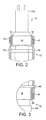
- Figure 1 shows an actuator arrangement 10 comprising a known piezoelectric actuator 20 that has been encapsulated in accordance with the method of the present invention.
- the actuator 20 comprises at least one piezoelectric element (not shown), and is suitable for use in a fuel injector of an internal combustion engine.
- the actuator 20 includes a generally cylindrical body section 12, comprising a central major portion 125 containing a piezoelectric element or stack, and first and second ends.
- a flexible sleeve 50 having first and second ends corresponding to the first and second ends respectively of the actuator 20, and which enshrouds and is conformed to the contours of the actuator 20.
- the sleeve 50 extends along the length of the actuator 20 from the upper end piece 14 to the lower end piece 16.
- the intermediate layers 70, 80 comprise a cured or set sealant material, such as an adhesive, such that the intermediate layers 70, 80 bond the sleeve 50 to, respectively, the portions 18, 19 to form a fluid-tight seal at either end of the actuator 20.
- the intermediate layers 70, 80 comprise a core-shell toughened epoxy with high cross-linking density and a glass transition temperature above 90 °C.
- the actuator 20 is encapsulated as follows. An adhesion promoter is applied to the exterior surface of the two end pieces 14, 16 at the respective portions 18, 19 and subsequently cured. The adhesion promoter is also applied to the interior surface of sleeve 50 and cured.
- Adhesive is applied to the portions 18, 19 on top of the area previously treated with adhesion promoter.
- the sleeve 50 is applied so as to enshroud the actuator 20 such that the interior surface of the sleeve 50, previously treated with adhesion promoter, contacts the adhesive.
- the adhesive could optionally be applied to the interior surface of the sleeve 50 instead of, or in addition to, the exterior surface of the end pieces 14, 16.
- the adhesive contacts a surface that has been treated with adhesion promoter although, optionally, the adhesive may contact a surface that has not been treated with adhesion promoter. It is preferred that the adhesion promoter and adhesive are not applied to the surface of central portion 125, which contains the piezoelectric stack.
- adhesive may be applied to a thickness of between about 50 nanometers and about 200 micrometers.
- adhesive may be applied to a thickness of 10 to 50 micrometers.
- the adhesion promoter of the present invention may be any suitable coupling agent, but is preferably a silane, suitably a functionalised silane.
- the adhesion promoter preferably comprises one or more functional groups adapted for reaction with the surfaces to which it is applied, and one or more functional groups adapted for reaction with the sealant layer.
- Suitable coupling agents/adhesion promoters may be generally described by the following formula: Y a - L - M - X b wherein Y is an organofunctional group, L is a linker, M is preferably a metal or semi-metal (metalloid) atom, and X is a hydrolysable group.
- the organofunctional group (Y) is adapted to react with functional groups of the adhesive
- the hydrolysable group (X) is adapted to react with the surface of the end pieces 14, 16 and/or the sleeve 50.
- this results in covalent bonding between the adhesive and the surface.
- M is preferably silicon, or a transition metal such as aluminium, titanium or zirconium.
- atom M may be selected from organic coupling agents where M is, for example, a carbon atom.
- the organofunctional group Y may be selected from amino (R-NH)or amine (R-NH 2 ) groups, where R is an organic group being either aliphatic or aromatic or another amino group.
- Y may be selected from epoxy, isocyanate, methacrylate or vinyl groups.
- X may also comprise methyl, ethyl or propyl groups,or acyloxy, halogen or amine.
- adhesion promoter may be selected from the list comprising:
- the adhesion promoter may be adapted to react with itself to form a very thin layer.
- the adhesion promoter may comprise functional groups that can react upon the application of heat.
- the application of adhesion promoter should lead to a change in surface tension of the surface to which it is applied.
- the adhesion promoter is applied to the surface of the portions 18, 19 and/or the sleeve 50 in the form of a resin, but may optionally be a gel, liquid, powder, or any other suitable form.
- the adhesion promoter may be deposited using a deposition technique such as, for example, dipping, spraying, spin coating or vapour deposition.
- the adhesion promoter may be cured by heat treatment, or by irradiation, or by evaporation of solvent, or by exposure to ambient humidity. It will be appreciated by one skilled in the art that any one of these methods may be more or less suited to curing the particular adhesion promoter used. In addition, the adhesive may be cured by similar methods.
- the sealant material used to form the intermediate layers 70, 80 may be selected from the list comprising thermosets or elastomers.
- Suitable elastomers may include silicones, fluorosilicones and fluorocarbon polymers.
- Suitable thermosets may include epoxies and cyanurates.
- the adhesive is a toughened epoxy, comprising tougheners selected from rubber tougheners or core-shell tougheners. Most suitably the adhesive is a core-shell toughened epoxy, and has a high cross-linking density.
- the adhesive has a glass transition temperature above 80 °C, preferably above 90 °C.
- the adhesive material may be adapted to contain advantageous materials or substances, for example free radical or ionic species scavenger compounds or preservatives.
- the sleeve 50 comprises a tube of heat-shrink material with open first and second ends, and is made to shrink around the actuator 20 by the application of heat.
- the adhesion promoter and/or adhesive is/are adapted such that they are not fully cured by the process of heat-shrinking the sleeve 50.
- a further heat treatment may be applied after the sleeve has been shrunk, in order to ensure full reaction of the adhesive with the adhesion promoter and to maximise adhesion strength.
- clips 30, 40 are provided at the first and second ends of the actuator 20. Clips of this kind are disclosed fully in, for example, the Applicant's co-pending application EP 05256852 , so will not be described in detail here.
- the clips 30, 40 are positioned externally with respect to the sleeve 50, such that the interior surface of the clips 30, 40 bears against the exterior of the sleeve 50 and exerts a constrictive force upon thereon that is sufficient to urge the interior surface of the sleeve 50 against the intermediate layers 70, 80.
- One of the clips 30 encircles the upper end piece 14 just short of electrical connector 145, whilst the other clip 40 encircles the lower end piece 16 just short of load transmitting member 165.
- the clips 30, 40 are applied over the sleeve 50 such that the interior surface of the sleeve 50, coated with dry adhesion promoter, is held against the intermediate layers 70, 80.
- the sleeve 50 is an example of various shrouds that could be used to enshroud the actuator 20.
- the shroud is a tube with first and second open ends such that the actuator 20 can be inserted into the open tube.
- the shroud is composed of a heat shrink polymer that can be made to shrink to fit the contours of the enshrouded actuator upon the application of heat.
- the shroud is formed from a fluoropolymer such as ethylene tetrafluoroethylene (ETFE), polytetrafluoroethylene (PTFE), fluorinated ethylene propylene (FEP), perfluoroalkoxy (PFA), or polyvinylidene fluoride (PVDF).
- the shroud may also be a high performance thermoplastic overmoulding, suitably a semi-crystalline thermoplastic.
- thermoplastic overmoulding examples include polyphenylene sulfide (PPS), polyamidimides (PAI), polysulfones (PSU), polyethersulfones (PES), polybenzimidazoles (PBI), polyetherketones (PEK), polyetheretherketones (PEEK), polyetherimide (PEI), polyimide (PI), polyphenylenterephtalamide (PPA), and liquid crystalline polymers (LCP).
- PPS polyphenylene sulfide
- PAI polyamidimides
- PSU polysulfones
- PES polybenzimidazoles
- PEK polyetherketones
- PEEK polyetheretherketones
- PEI polyetherimide
- PI polyimide
- PPA polyphenylenterephtalamide
- LCP liquid crystalline polymers
- the surface of the portions 18, 19 of the end pieces 14, 16 and/or the shroud 50 may be treated prior to the application of adhesion promoter, or prior to contact with the intermediate layer 70, 80 if adhesion promoter is not used, in order to further improve adhesion to the intermediate layer 70, 80.
- a suitable treatment may comprise, for example, chemical etching.
- a further suitable treatment process is to apply a gas plasma treatment to the active portions 18, 19 of the end pieces 14, 16 prior to the application of the adhesion promoter.
- Plasma treatment processes are effective at altering the surface of materials to improve their reactive properties.
- the applied gas plasma increases the functional groups present on the surface of the end pieces 14, 16.
- the adhesion promoter bonds with the functional groups. The adhesive bonds with the adhesion promoter more effectively.
- a polymeric passivation layer may be provided immediately adjacent the surface of the stack, radially inwardly of the sleeve 50.
- a passivation layer is known to be suitable for suppressing electrical arcing over the surface of the stack, sometimes referred to in the art as 'surface flashovers'.
- Another such layer may be a barrier layer as described, for example, in the Applicant's co-pending applications GB 0602956.5 and GB 0604467.1 .
- adhesive may be provided between the surface of the enshrouded actuator and the sleeve or barrier layer adjacent to it, and between this and each additional layer. It should therefore be appreciated that the term 'actuator' should be construed as referring to a complete functioning piezoelectric device including all protective measures, e.g. as described above, applied thereto.
- At least one filler material or other substance disposed between the exterior surface of the actuator and the interior surface of the sleeve.
- the actuator 20 may be of any type.
- the encapsulated actuator arrangement When the encapsulated actuator arrangement is disposed within a fuel injector system, it may be exposed to fuel comprising diesel, biodiesel, gasoline or mixtures optionally containing water and/or alcohol.
Landscapes
- Engineering & Computer Science (AREA)
- Chemical & Material Sciences (AREA)
- Combustion & Propulsion (AREA)
- Mechanical Engineering (AREA)
- General Engineering & Computer Science (AREA)
- Manufacturing & Machinery (AREA)
- Fuel-Injection Apparatus (AREA)
- Sealing Material Composition (AREA)
- Adhesives Or Adhesive Processes (AREA)
Claims (14)
- Verfahren zum Ummanteln eines Aktors zur Verwendung in einer Kraftstoffeinspritzvorrichtung, das die folgenden Schritte beinhaltet:Bereitstellen eines Aktors (20) mit einem Körperabschnitt (12), einem ersten Endstück (14) und einem zweiten Endstück (16),Bereitstellen einer flexiblen Ummantelung (50) mit einem ersten und einem zweiten Ende,Auftragen eines Dichtungsmaterials auf wenigstens einen Abschnitt (18, 19) einer Außenfläche der Endstücke (14, 16) und/oder auf wenigstens einen entsprechenden Teil der Ummantelung (50), so dass das Dichtungsmaterial nur zwischen der Ummantelung und den Endstücken angeordnet ist, undUmmanteln des Aktors (20) mit der Ummantelung (50), so dass die Ummantelung (50) von dem ersten Endstück (14) bis zum zweiten Endstück (16) längs entlang dem Aktor (20) verläuft und an die Konturen des Aktors (20) angepasst ist und so dass das Dichtungsmaterial eine Zwischenschicht (70, 80) zwischen den Endstücken (14, 16) und der Ummantelung (50) bereitstellt und eine fluiddichte Abdichtung zwischen ihnen bildet.
- Verfahren nach Anspruch 1, bei dem die Ummantelung (50) ein aus einem Fluorpolymer und einem thermoplastischen Polymer ausgewähltes Material aufweist.
- Verfahren nach Anspruch 1 oder Anspruch 2, bei dem das Dichtungsmaterial ein Klebstoff ist, der vorzugsweise aus der Gruppe ausgewählt wird, die Silikone, Fluorsilikone, Fluor-Kohlenstoff-Polymere, Epoxidharze und Cyanurate oder ein gehärtetes Epoxidharz, vorzugsweise ein gehärtetes Core-Shell-Epoxidharz, beinhaltet.
- Verfahren nach einem der vorhergehenden Ansprüche, bei dem das Verfahren den zusätzlichen Schritt des Auftragens eines Haftvermittlers auf wenigstens eine Oberfläche beinhaltet, die mit dem Dichtungsmaterial in Kontakt kommen wird, bevor das Dichtungsmaterial aufgetragen wird.
- Verfahren nach Anspruch 4, bei dem der Haftvermittler einen Haftungsförderer beinhaltet.
- Verfahren nach Anspruch 5, bei dem der Haftungsförderer ein Silan beinhaltet.
- Verfahren nach einem der Ansprüche 4 bis 6, das ferner den Schritt des Anwendens eines Gasplasmabehandlungsprozesses auf die wenigstens eine Oberfläche beinhaltet, bevor der Haftvermittler aufgetragen wird.
- Verfahren nach einem der Ansprüche 4 bis 6, das ferner den Schritt des Aufbringens einer Schicht von amorphem Silikat auf die wenigstens eine Oberfläche mithilfe eines verbrennungsinduzierten chemischen Gasphasenabscheidungsverfahrens, bevor der Haftvermittler aufgebracht wird, beinhaltet.
- Verfahren nach einem der vorhergehenden Ansprüche, bei dem die Ummantelung mehrere Schichten oder Beschichtungen aufweist.
- Verfahren nach Anspruch 9, bei dem wenigstens eine Schicht oder Beschichtung ein Fluorpolymer aufweist.
- Verfahren nach Anspruch 9 oder Anspruch 10, bei dem wenigstens eine Schicht oder Beschichtung ein Material aufweist, das zur Regulierung der Permeation von ionischen Species durch die Ummantelung angepasst ist.
- Verfahren nach einem der vorhergehenden Ansprüche, wobei das Verfahren den zusätzlichen Schritt des Anbringens eines Sicherungselements (30, 40) außen an der Ummantelung (50) aufweist, wobei das Sicherungselement die Aufgabe hat, eine einengende Kraft auf die Ummantelung (50) auszuüben und die Ummantelung (50) in Richtung auf die darunterliegende Zwischenschicht (70, 80) zu drücken.
- Ummantelte Aktoranordnung (10), die Folgendes beinhaltet:einen Aktor (20) mit einem Körperabschnitt (12), einem ersten Endstück (14) und einem zweiten Endstück (16) undeine Ummantelung (50), die ein Fluorpolymer aufweist,dadurch gekennzeichnet, dass die Anordnung (10) ferner Folgendes aufweist:eine Zwischenschicht (70), die ein Dichtungsmaterial aufweist, wobei die Zwischenschicht (70) zwischen einem Abschnitt (18) des ersten Endstücks (14) und der Ummantelung (50) angeordnet ist, undeine Zwischenschicht (80), die ein Dichtungsmaterial aufweist, wobei die Zwischenschicht (80) zwischen einem Abschnitt (19) des zweiten Endstücks (16) und der Ummantelung (50) angeordnet ist,so dass die Dichtungsmittelschichten (70, 80) nur zwischen der Ummantelung (50) und den Endstücken (14, 16) angeordnet sind, um dadurch eine fluiddichte Abdichtung zwischen den Endstücken (14, 16) und der Ummantelung (50) zu bilden,wobei die Ummantelung (50) flexibel ist und von dem ersten Endstück (14) bis zum zweiten Endstück (16) längs entlang dem Aktor (20) verläuft und den Konturen des Aktors (50) angepasst ist.
- Ummantelte Aktoranordnung (10) nach Anspruch 3, bei der das Dichtungsmaterial einen Klebstoff aufweist, der aus der Gruppe ausgewählt ist, die Silikone, Fluorsilikone, Fluor-Kohlenstoff-Polymere, Epoxidharze und Cyanurate oder ein gehärtetes Epoxidharz, vorzugsweise ein gehärtetes Core-Shell-Epoxidharz beinhaltet.
Priority Applications (1)
| Application Number | Priority Date | Filing Date | Title |
|---|---|---|---|
| EP07705254A EP2013921B1 (de) | 2006-05-03 | 2007-02-21 | Verfahren zum einhüllen eines aktors |
Applications Claiming Priority (3)
| Application Number | Priority Date | Filing Date | Title |
|---|---|---|---|
| EP06252352 | 2006-05-03 | ||
| PCT/GB2007/000623 WO2007128948A1 (en) | 2006-05-03 | 2007-02-21 | Method for enshrouding an actuator |
| EP07705254A EP2013921B1 (de) | 2006-05-03 | 2007-02-21 | Verfahren zum einhüllen eines aktors |
Publications (2)
| Publication Number | Publication Date |
|---|---|
| EP2013921A1 EP2013921A1 (de) | 2009-01-14 |
| EP2013921B1 true EP2013921B1 (de) | 2011-05-11 |
Family
ID=36795454
Family Applications (1)
| Application Number | Title | Priority Date | Filing Date |
|---|---|---|---|
| EP07705254A Not-in-force EP2013921B1 (de) | 2006-05-03 | 2007-02-21 | Verfahren zum einhüllen eines aktors |
Country Status (5)
| Country | Link |
|---|---|
| US (1) | US8236115B2 (de) |
| EP (1) | EP2013921B1 (de) |
| JP (1) | JP5031824B2 (de) |
| AT (1) | ATE509377T1 (de) |
| WO (1) | WO2007128948A1 (de) |
Families Citing this family (11)
| Publication number | Priority date | Publication date | Assignee | Title |
|---|---|---|---|---|
| DE102008003821A1 (de) * | 2008-01-10 | 2009-07-16 | Epcos Ag | Piezoelektrische Aktoreinheit |
| EP2086028B1 (de) * | 2008-01-30 | 2011-09-21 | Delphi Technologies Holding S.à.r.l. | Klemme |
| DE102008010561A1 (de) * | 2008-02-22 | 2009-09-03 | Robert Bosch Gmbh | Einspritzventil mit Magnetverklebung |
| DE102009046377A1 (de) * | 2009-11-04 | 2011-05-26 | Robert Bosch Gmbh | Kraftstoffeinspritzventil |
| EP2343746B1 (de) | 2010-01-11 | 2012-10-24 | Delphi Technologies Holding S.à.r.l. | Verfahren zur Verkapselung eines Aktuators mit einem piezoelektrischen Aktuatorstapel |
| EP2372139B1 (de) | 2010-03-25 | 2012-10-31 | Delphi Technologies Holding S.à.r.l. | Aktuatoranordnung zur Verwendung mit einem Kraftstoffinjektor |
| EP2378107A1 (de) * | 2010-04-19 | 2011-10-19 | Delphi Technologies Holding S.à.r.l. | Aktuatoranordnung zur Verwendung mit einem Kraftstoffinjektor |
| FR2985215B1 (fr) | 2011-12-28 | 2014-09-19 | Saint Gobain Performance Plast | Revetements polymeres deposes sur des substrats par des techniques de projection thermique |
| CN103182808A (zh) | 2011-12-28 | 2013-07-03 | 圣戈班高功能塑料集团 | 一种包括含氟聚合物表面层以及非氟聚合物过渡层的多层复合物 |
| PL2867019T3 (pl) | 2012-06-29 | 2023-04-24 | Saint-Gobain Performance Plastics Pampus Gmbh | Łożysko ślizgowe zawierające system podkładu jako promotor przyczepności |
| KR101663975B1 (ko) | 2012-09-28 | 2016-10-12 | 생―고뱅 퍼포먼스 플라스틱스 팜푸스 게엠베하 | 조합성 접착 슬라이드 층을 가지는 무-보수 슬라이드 베어링 |
Family Cites Families (16)
| Publication number | Priority date | Publication date | Assignee | Title |
|---|---|---|---|---|
| US4465547A (en) * | 1983-09-29 | 1984-08-14 | General Electric Company | Method of bonding a poly (vinylidene fluoride) solid to a solid substrate |
| KR900007766B1 (ko) * | 1985-06-26 | 1990-10-19 | 더 다우 케미칼 캄파니 | 고무-개질 에폭시 화합물 |
| JPH02276280A (ja) * | 1989-04-18 | 1990-11-13 | Toyota Motor Corp | 圧電積層体 |
| US5326643A (en) * | 1991-10-07 | 1994-07-05 | International Business Machines Corporation | Adhesive layer in multi-level packaging and organic material as a metal diffusion barrier |
| US5500279A (en) * | 1994-08-26 | 1996-03-19 | Eastman Kodak Company | Laminated metal structure and metod of making same |
| US5882466A (en) * | 1996-08-08 | 1999-03-16 | Minnesota Mining And Manufacturing Company | Aqueous bonding composition |
| US5776235A (en) * | 1996-10-04 | 1998-07-07 | Dow Corning Corporation | Thick opaque ceramic coatings |
| JPH11106443A (ja) | 1997-10-01 | 1999-04-20 | Sekisui Chem Co Ltd | 塩化ビニル系グラフト樹脂及び共重合体ラテックスの製造方法 |
| DE19818068A1 (de) * | 1998-04-22 | 1999-10-28 | Siemens Ag | Piezoelektronischer Aktor für einen Stellantrieb |
| DE19914411A1 (de) * | 1999-03-30 | 2000-10-12 | Bosch Gmbh Robert | Piezoelektrischer Aktor |
| JP2002053735A (ja) | 2000-08-09 | 2002-02-19 | Sumitomo Bakelite Co Ltd | エポキシ樹脂組成物及び半導体装置 |
| GB0102500D0 (en) * | 2001-02-01 | 2001-03-14 | Delphi Tech Inc | Method of assembling an actuator arrangement |
| JP3900918B2 (ja) | 2001-12-10 | 2007-04-04 | 株式会社デンソー | 圧電アクチュエータ |
| JP4036440B2 (ja) * | 2002-03-29 | 2008-01-23 | 東洋合成工業株式会社 | 新規な感光性化合物及び感光性樹脂並びに感光性組成物 |
| US7250477B2 (en) * | 2002-12-20 | 2007-07-31 | General Electric Company | Thermoset composite composition, method, and article |
| JP2004251368A (ja) | 2003-02-20 | 2004-09-09 | Air Water Inc | 弁用シートリングの製造方法、弁体の製造方法 |
-
2007
- 2007-02-21 WO PCT/GB2007/000623 patent/WO2007128948A1/en not_active Ceased
- 2007-02-21 EP EP07705254A patent/EP2013921B1/de not_active Not-in-force
- 2007-02-21 US US12/226,946 patent/US8236115B2/en not_active Expired - Fee Related
- 2007-02-21 AT AT07705254T patent/ATE509377T1/de not_active IP Right Cessation
- 2007-02-21 JP JP2009508445A patent/JP5031824B2/ja not_active Expired - Fee Related
Also Published As
| Publication number | Publication date |
|---|---|
| EP2013921A1 (de) | 2009-01-14 |
| US20090304957A1 (en) | 2009-12-10 |
| JP5031824B2 (ja) | 2012-09-26 |
| US8236115B2 (en) | 2012-08-07 |
| JP2009535564A (ja) | 2009-10-01 |
| ATE509377T1 (de) | 2011-05-15 |
| WO2007128948A1 (en) | 2007-11-15 |
Similar Documents
| Publication | Publication Date | Title |
|---|---|---|
| US8236115B2 (en) | Method for enshrouding an actuator | |
| EP1984960B1 (de) | Piezoelektrischer aktuator | |
| EP1984959A2 (de) | Dämmbeschichtungen für eine piezoelektrische vorrichtung | |
| EP4235134A2 (de) | Druckdetektor mit einer sensoreinheit | |
| CN100373650C (zh) | 用于电气部件的钝化材料及多层结构的压电部件 | |
| KR101012065B1 (ko) | 밀폐 전자 습식 디바이스 | |
| US10014757B2 (en) | Polymer-based layer structure with an oleophobic/hydrophobic surface, and electric machine comprising such a layer structure | |
| CN111434800B (zh) | 具有基于Si,C和O的粘接层的复合材料 | |
| US20040113525A1 (en) | Method of assembling an actuator arrangement | |
| US9475586B2 (en) | Method for sealing a fuel tank | |
| WO2005005554A2 (en) | Moisture-resistant nano-particle material and its applications | |
| US11548194B2 (en) | Method for manufacturing fluid device composite member | |
| EP1992022B1 (de) | Verkapselungsanordnung für eine elektronische komponente | |
| US20240132690A1 (en) | Coated Aerogels | |
| US20130328448A1 (en) | Piezo actuator with protection against environmental influences | |
| US20100031929A1 (en) | Piezoelectric Actuator with a Sheathing Composed of a Composite Material | |
| CN104094108B (zh) | 用于对废气传感器的壳体进行密封的堵头、废气传感器以及废气传感器的制造 | |
| US20100258086A1 (en) | Piezoelectric Device | |
| KR102569441B1 (ko) | 도료 조성물 및 도장 물품 | |
| JP7120236B2 (ja) | フィルムロールおよびフィルム束 | |
| DE102007037550A1 (de) | Piezoelektrisches Aktormodul und Brennstoffeinspritzventil | |
| JP2009534826A (ja) | カバーを備えたピエゾアクチュエータモジュールおよびカバーを備えたピエゾアクチュエータモジュールの製造方法 | |
| WO2011046059A1 (ja) | 液中物質検出装置の製造方法及び液中物質検出装置 | |
| DE102010062467A1 (de) | Piezoelektrisches Stellglied und Herstellungsverfahren von diesem | |
| Beck et al. | Hermetically Sealed Piezoceramic Actuators |
Legal Events
| Date | Code | Title | Description |
|---|---|---|---|
| PUAI | Public reference made under article 153(3) epc to a published international application that has entered the european phase |
Free format text: ORIGINAL CODE: 0009012 |
|
| 17P | Request for examination filed |
Effective date: 20081006 |
|
| AK | Designated contracting states |
Kind code of ref document: A1 Designated state(s): AT BE BG CH CY CZ DE DK EE ES FI FR GB GR HU IE IS IT LI LT LU LV MC NL PL PT RO SE SI SK TR |
|
| AX | Request for extension of the european patent |
Extension state: AL BA HR MK RS |
|
| 17Q | First examination report despatched |
Effective date: 20091022 |
|
| RAP1 | Party data changed (applicant data changed or rights of an application transferred) |
Owner name: DELPHI TECHNOLOGIES HOLDING S.A.R.L. |
|
| GRAP | Despatch of communication of intention to grant a patent |
Free format text: ORIGINAL CODE: EPIDOSNIGR1 |
|
| DAX | Request for extension of the european patent (deleted) | ||
| GRAS | Grant fee paid |
Free format text: ORIGINAL CODE: EPIDOSNIGR3 |
|
| GRAA | (expected) grant |
Free format text: ORIGINAL CODE: 0009210 |
|
| AK | Designated contracting states |
Kind code of ref document: B1 Designated state(s): AT BE BG CH CY CZ DE DK EE ES FI FR GB GR HU IE IS IT LI LT LU LV MC NL PL PT RO SE SI SK TR |
|
| REG | Reference to a national code |
Ref country code: GB Ref legal event code: FG4D |
|
| REG | Reference to a national code |
Ref country code: CH Ref legal event code: EP |
|
| REG | Reference to a national code |
Ref country code: IE Ref legal event code: FG4D |
|
| REG | Reference to a national code |
Ref country code: DE Ref legal event code: R096 Ref document number: 602007014512 Country of ref document: DE Effective date: 20110622 |
|
| REG | Reference to a national code |
Ref country code: NL Ref legal event code: VDEP Effective date: 20110511 |
|
| PG25 | Lapsed in a contracting state [announced via postgrant information from national office to epo] |
Ref country code: LT Free format text: LAPSE BECAUSE OF FAILURE TO SUBMIT A TRANSLATION OF THE DESCRIPTION OR TO PAY THE FEE WITHIN THE PRESCRIBED TIME-LIMIT Effective date: 20110511 Ref country code: SE Free format text: LAPSE BECAUSE OF FAILURE TO SUBMIT A TRANSLATION OF THE DESCRIPTION OR TO PAY THE FEE WITHIN THE PRESCRIBED TIME-LIMIT Effective date: 20110511 Ref country code: PT Free format text: LAPSE BECAUSE OF FAILURE TO SUBMIT A TRANSLATION OF THE DESCRIPTION OR TO PAY THE FEE WITHIN THE PRESCRIBED TIME-LIMIT Effective date: 20110912 |
|
| PG25 | Lapsed in a contracting state [announced via postgrant information from national office to epo] |
Ref country code: LV Free format text: LAPSE BECAUSE OF FAILURE TO SUBMIT A TRANSLATION OF THE DESCRIPTION OR TO PAY THE FEE WITHIN THE PRESCRIBED TIME-LIMIT Effective date: 20110511 Ref country code: GR Free format text: LAPSE BECAUSE OF FAILURE TO SUBMIT A TRANSLATION OF THE DESCRIPTION OR TO PAY THE FEE WITHIN THE PRESCRIBED TIME-LIMIT Effective date: 20110812 Ref country code: BE Free format text: LAPSE BECAUSE OF FAILURE TO SUBMIT A TRANSLATION OF THE DESCRIPTION OR TO PAY THE FEE WITHIN THE PRESCRIBED TIME-LIMIT Effective date: 20110511 Ref country code: IS Free format text: LAPSE BECAUSE OF FAILURE TO SUBMIT A TRANSLATION OF THE DESCRIPTION OR TO PAY THE FEE WITHIN THE PRESCRIBED TIME-LIMIT Effective date: 20110911 Ref country code: SI Free format text: LAPSE BECAUSE OF FAILURE TO SUBMIT A TRANSLATION OF THE DESCRIPTION OR TO PAY THE FEE WITHIN THE PRESCRIBED TIME-LIMIT Effective date: 20110511 Ref country code: ES Free format text: LAPSE BECAUSE OF FAILURE TO SUBMIT A TRANSLATION OF THE DESCRIPTION OR TO PAY THE FEE WITHIN THE PRESCRIBED TIME-LIMIT Effective date: 20110822 Ref country code: FI Free format text: LAPSE BECAUSE OF FAILURE TO SUBMIT A TRANSLATION OF THE DESCRIPTION OR TO PAY THE FEE WITHIN THE PRESCRIBED TIME-LIMIT Effective date: 20110511 Ref country code: AT Free format text: LAPSE BECAUSE OF FAILURE TO SUBMIT A TRANSLATION OF THE DESCRIPTION OR TO PAY THE FEE WITHIN THE PRESCRIBED TIME-LIMIT Effective date: 20110511 Ref country code: CY Free format text: LAPSE BECAUSE OF FAILURE TO SUBMIT A TRANSLATION OF THE DESCRIPTION OR TO PAY THE FEE WITHIN THE PRESCRIBED TIME-LIMIT Effective date: 20110511 |
|
| PG25 | Lapsed in a contracting state [announced via postgrant information from national office to epo] |
Ref country code: NL Free format text: LAPSE BECAUSE OF FAILURE TO SUBMIT A TRANSLATION OF THE DESCRIPTION OR TO PAY THE FEE WITHIN THE PRESCRIBED TIME-LIMIT Effective date: 20110511 |
|
| PG25 | Lapsed in a contracting state [announced via postgrant information from national office to epo] |
Ref country code: CZ Free format text: LAPSE BECAUSE OF FAILURE TO SUBMIT A TRANSLATION OF THE DESCRIPTION OR TO PAY THE FEE WITHIN THE PRESCRIBED TIME-LIMIT Effective date: 20110511 Ref country code: EE Free format text: LAPSE BECAUSE OF FAILURE TO SUBMIT A TRANSLATION OF THE DESCRIPTION OR TO PAY THE FEE WITHIN THE PRESCRIBED TIME-LIMIT Effective date: 20110511 |
|
| PG25 | Lapsed in a contracting state [announced via postgrant information from national office to epo] |
Ref country code: PL Free format text: LAPSE BECAUSE OF FAILURE TO SUBMIT A TRANSLATION OF THE DESCRIPTION OR TO PAY THE FEE WITHIN THE PRESCRIBED TIME-LIMIT Effective date: 20110511 Ref country code: SK Free format text: LAPSE BECAUSE OF FAILURE TO SUBMIT A TRANSLATION OF THE DESCRIPTION OR TO PAY THE FEE WITHIN THE PRESCRIBED TIME-LIMIT Effective date: 20110511 Ref country code: RO Free format text: LAPSE BECAUSE OF FAILURE TO SUBMIT A TRANSLATION OF THE DESCRIPTION OR TO PAY THE FEE WITHIN THE PRESCRIBED TIME-LIMIT Effective date: 20110511 Ref country code: DK Free format text: LAPSE BECAUSE OF FAILURE TO SUBMIT A TRANSLATION OF THE DESCRIPTION OR TO PAY THE FEE WITHIN THE PRESCRIBED TIME-LIMIT Effective date: 20110511 |
|
| PLBE | No opposition filed within time limit |
Free format text: ORIGINAL CODE: 0009261 |
|
| STAA | Information on the status of an ep patent application or granted ep patent |
Free format text: STATUS: NO OPPOSITION FILED WITHIN TIME LIMIT |
|
| 26N | No opposition filed |
Effective date: 20120214 |
|
| PG25 | Lapsed in a contracting state [announced via postgrant information from national office to epo] |
Ref country code: IT Free format text: LAPSE BECAUSE OF FAILURE TO SUBMIT A TRANSLATION OF THE DESCRIPTION OR TO PAY THE FEE WITHIN THE PRESCRIBED TIME-LIMIT Effective date: 20110511 |
|
| REG | Reference to a national code |
Ref country code: DE Ref legal event code: R097 Ref document number: 602007014512 Country of ref document: DE Effective date: 20120214 |
|
| PG25 | Lapsed in a contracting state [announced via postgrant information from national office to epo] |
Ref country code: MC Free format text: LAPSE BECAUSE OF NON-PAYMENT OF DUE FEES Effective date: 20120229 |
|
| REG | Reference to a national code |
Ref country code: CH Ref legal event code: PL |
|
| GBPC | Gb: european patent ceased through non-payment of renewal fee |
Effective date: 20120221 |
|
| PG25 | Lapsed in a contracting state [announced via postgrant information from national office to epo] |
Ref country code: CH Free format text: LAPSE BECAUSE OF NON-PAYMENT OF DUE FEES Effective date: 20120229 Ref country code: LI Free format text: LAPSE BECAUSE OF NON-PAYMENT OF DUE FEES Effective date: 20120229 |
|
| REG | Reference to a national code |
Ref country code: IE Ref legal event code: MM4A |
|
| PG25 | Lapsed in a contracting state [announced via postgrant information from national office to epo] |
Ref country code: IE Free format text: LAPSE BECAUSE OF NON-PAYMENT OF DUE FEES Effective date: 20120221 Ref country code: GB Free format text: LAPSE BECAUSE OF NON-PAYMENT OF DUE FEES Effective date: 20120221 |
|
| PG25 | Lapsed in a contracting state [announced via postgrant information from national office to epo] |
Ref country code: BG Free format text: LAPSE BECAUSE OF FAILURE TO SUBMIT A TRANSLATION OF THE DESCRIPTION OR TO PAY THE FEE WITHIN THE PRESCRIBED TIME-LIMIT Effective date: 20110811 |
|
| PG25 | Lapsed in a contracting state [announced via postgrant information from national office to epo] |
Ref country code: TR Free format text: LAPSE BECAUSE OF FAILURE TO SUBMIT A TRANSLATION OF THE DESCRIPTION OR TO PAY THE FEE WITHIN THE PRESCRIBED TIME-LIMIT Effective date: 20110511 |
|
| PG25 | Lapsed in a contracting state [announced via postgrant information from national office to epo] |
Ref country code: LU Free format text: LAPSE BECAUSE OF NON-PAYMENT OF DUE FEES Effective date: 20120221 |
|
| REG | Reference to a national code |
Ref country code: FR Ref legal event code: TP Owner name: DELPHI INTERNATIONAL OPERATIONS LUXEMBOURG S.A, LU Effective date: 20140516 |
|
| PG25 | Lapsed in a contracting state [announced via postgrant information from national office to epo] |
Ref country code: HU Free format text: LAPSE BECAUSE OF FAILURE TO SUBMIT A TRANSLATION OF THE DESCRIPTION OR TO PAY THE FEE WITHIN THE PRESCRIBED TIME-LIMIT Effective date: 20070221 |
|
| REG | Reference to a national code |
Ref country code: DE Ref legal event code: R081 Ref document number: 602007014512 Country of ref document: DE Owner name: DELPHI INTERNATIONAL OPERATIONS LUXEMBOURG S.A, LU Free format text: FORMER OWNER: DELPHI TECHNOLOGIES HOLDING S.A.R.L., BASCHARAGE, LU Effective date: 20140702 |
|
| REG | Reference to a national code |
Ref country code: FR Ref legal event code: PLFP Year of fee payment: 9 |
|
| PGFP | Annual fee paid to national office [announced via postgrant information from national office to epo] |
Ref country code: DE Payment date: 20150226 Year of fee payment: 9 |
|
| PGFP | Annual fee paid to national office [announced via postgrant information from national office to epo] |
Ref country code: FR Payment date: 20150217 Year of fee payment: 9 |
|
| REG | Reference to a national code |
Ref country code: DE Ref legal event code: R119 Ref document number: 602007014512 Country of ref document: DE |
|
| REG | Reference to a national code |
Ref country code: FR Ref legal event code: ST Effective date: 20161028 |
|
| PG25 | Lapsed in a contracting state [announced via postgrant information from national office to epo] |
Ref country code: FR Free format text: LAPSE BECAUSE OF NON-PAYMENT OF DUE FEES Effective date: 20160229 Ref country code: DE Free format text: LAPSE BECAUSE OF NON-PAYMENT OF DUE FEES Effective date: 20160901 |