EP2014198B1 - Ausklappbarer Bettrahmen und Bett, das einen solchen Bettrahmen umfasst - Google Patents
Ausklappbarer Bettrahmen und Bett, das einen solchen Bettrahmen umfasst Download PDFInfo
- Publication number
- EP2014198B1 EP2014198B1 EP20070291540 EP07291540A EP2014198B1 EP 2014198 B1 EP2014198 B1 EP 2014198B1 EP 20070291540 EP20070291540 EP 20070291540 EP 07291540 A EP07291540 A EP 07291540A EP 2014198 B1 EP2014198 B1 EP 2014198B1
- Authority
- EP
- European Patent Office
- Prior art keywords
- bed
- legs
- thighs
- bed base
- parts
- Prior art date
- Legal status (The legal status is an assumption and is not a legal conclusion. Google has not performed a legal analysis and makes no representation as to the accuracy of the status listed.)
- Active
Links
Images


Classifications
-
- A—HUMAN NECESSITIES
- A47—FURNITURE; DOMESTIC ARTICLES OR APPLIANCES; COFFEE MILLS; SPICE MILLS; SUCTION CLEANERS IN GENERAL
- A47C—CHAIRS; SOFAS; BEDS
- A47C20/00—Head-, foot- or like rests for beds, sofas or the like
- A47C20/04—Head-, foot- or like rests for beds, sofas or the like with adjustable inclination
- A47C20/041—Head-, foot- or like rests for beds, sofas or the like with adjustable inclination by electric motors
-
- A—HUMAN NECESSITIES
- A47—FURNITURE; DOMESTIC ARTICLES OR APPLIANCES; COFFEE MILLS; SPICE MILLS; SUCTION CLEANERS IN GENERAL
- A47C—CHAIRS; SOFAS; BEDS
- A47C20/00—Head-, foot- or like rests for beds, sofas or the like
- A47C20/08—Head-, foot- or like rests for beds, sofas or the like with means for adjusting two or more rests simultaneously
Definitions
- the invention relates to a bedding bedding deployable and a bed comprising such a bed base.
- beds comprising, in addition to a support, rolling or not, a bed base in several parts, including a central part - also called seat - is not generally reclining, but the other parts, that for the back and the head and usually also that for the legs, are reclining. While the back and head portion is generally tiltable to positions above the horizontal only, that is, it can only be raised from the horizontal and then back down horizontally, the leg section can often be tilted to positions both above and below the horizontal and then down or up towards the horizontal. Some of these beds are provided with separately tilting parts for the head and back and, similarly, for the thighs and legs.
- the tilting parts are often individually driven using rotary drive means such as rotating electrical machines or with the aid of jacks. But there are also beds with complex mechanisms where the complexity results mainly from a reduction in the number of motor sources obtained at the cost of a presence of many connecting bars, coupling elements and / or elements. of transmission.
- the support of such beds generally extends over the entire length of the bed base. Often, the support even surpasses the bed base and includes a frame surrounding the bed base on all four sides. This makes some manipulations of the bed and some gestures of use of this one difficult, even impossible.
- the bed is comfortable and allows, in addition to adjustment in a large number of positions, including easy access and exit.
- this comfort is often limited by the presence of a complex mechanism limiting the variation of the inclination of the part for the legs and, where appropriate, also for the thighs.
- the user of the bed is nevertheless limited in the choice of positions if the support frame prevents him from accessing or leaving the bed. .
- a bed having several parts and which is deployable in different positions is known from the document US-A-4,258,445 .
- the object of the invention is to propose at least a bed base, or even a bed with a bed frame, deployable having a simple structure and being easy to handle, while ensuring a wide variation of inclinations of the part or parts for thighs and legs.
- a bedding bedding deployable comprising at least four parts including a non-reclining center portion and at least one tiltable portion for the back and head, a tilt portion for the thighs and a tilt portion for the legs, the tiltable portions being pivotally mounted about the transverse pivot axes, and at least driving means for tilting, on command, the recliners for thighs and legs.
- the drive means for tilting the thigh and leg portions comprises a common drive source to which the thigh portion and the leg portion are connected so that the inclination of the part for the legs does not necessarily follow that of the part for the thighs and that the part for the legs can pass under a plane defined by the non-tilting central part, in order to be able to put the bed frame in chair position.
- the drive means for tilting the leg portion is connected to an axis of rotation driven directly by the drive means for tilting the thigh portion.
- the invention thus relates to the thighs and legs side of a deployable bed base and allows a user of a bed comprising such a bed base, using simple means, to tilt the legs, when they are at home. Horizon or above, to a lesser degree than the thighs so that you can rest or relax with knees slightly bent and yet fully supported without the need for cushions or other aids.
- the invention also makes it possible to incline the legs sharply downwards and with an inclination, taken in its absolute angular value, different from that of the thighs.
- the inclination of the parts for the thighs and for the legs and in particular the difference in inclination between the part for the thighs and that for the legs is obtained, according to one embodiment of the invention, by connecting the driving source to the portion for the thighs by at least one articulated arm and connecting the driving source to the leg portion by at least one arm fixed or adjustable length.
- the principle of the variable geometry of the training means of the parts for the thighs and the legs and the training of the part for the legs by the part for the thighs avoids loading the space below the bed base of a multitude of connecting rods, rods or other connecting elements and also allows, by placing the drive means directly on the bed base, to integrate the support of the bed on which the bed base rests, that in the measure where it possibly supports the common motor source.
- the drive means may be electric motors or cylinders or a combination of an electric motor with a jack, to name only training means most suitable for this type of bed base.
- the object of the invention is also achieved with a bed comprising a support by which the bed rests, rolling or stationary, on a floor and on which is mounted a bed base having the characteristics described above.
- the bed of the invention comprises a support having substantially the shape of a truncated frame on the side of the footboard.
- the bed frame is cantilevered relative to the support, at least the portion for the legs protruding from the support.
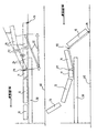
- a deployable bed base 10 comprises at least four parts, namely a central non-tilting portion 11 and at least three tilting portions.
- the tilting parts are on the one hand a part 12, 13 for the back and the head and, on the other hand, a portion 14 for the thighs and a portion 15 for the legs.
- the parts 12, 13 may be pivotally mounted to each other and may also be individually connected to drive means so as to tilt them separately.
- the parts 14 and 15 respectively for the thighs and for the legs are connected together by hinges represented for example on the figure 8 .
- the bed base of the invention 10 is mounted on a support 30 by which the bed thus formed rests on a floor 40.
- the portion 15 for the legs is provided with means 16 which allow it, when in contact with the ground 40, to roll on the ground.
- the means 16 may be in the form of rollers or in the form of side wheels and may be rigidly fixed to the leg portion 15, i.e. on a fixed axis, or to a leg of the leg. support giving some cushioning in support of the party 15 on the floor.
- the figure 1 represents the bed base of the invention in its basic position, that is to say all parts, inclinable or not, being in a horizontal position.
- the figure 2 represents the foundation of the invention with the portion 14 for the thighs and the portion 15 for the legs inclined relative to the horizontal.
- the figure 2 also shows that the tilting parts 12 to 15 are pivotally mounted about the transverse pivot axes P1 to P4 extending perpendicular to the plane of the figures.
- the figure 2 shows also that, according to the invention, when the portion 14 for the thighs is raised, the portion 15 for the legs is raised at the same time, but with a desired delay explained below.
- drive means represented by the force F1 with which they act on the parts 14, 15, give the part 14 an inclination D1 and that, at the same time, part of these drive means represented by the force F2 with which it acts on the part 15, gives the latter a resulting inclination D2 which is lower than the inclination D1 of the part 14.
- the drive means for changing the inclination of the parts for the thighs and the legs comprise a common driving source 21 to which the portion 14 for the thighs is connected directly, for example by fixing this part on the axis of a rotating electrical machine forming the common driving source, and to which the leg portion 15 is indirectly connected, for example by fixing an element 22 of adjustable length on the axis of the rotating electrical machine and by articulation of this element on the part for the legs.
- FIGS. 3 and 4 show how this provision of the invention can be used to other tilting movements of the parts 14, 15 respectively for the thighs and for the legs.
- the first movement is indicated in dotted lines. This is to lengthen the adjustable length member until the leg portion 15 has the same inclination as the portion 14 for the thighs.
- the second movement is achieved by changing the length of the adjustable length member by applying a force F3 on the leg portion 15.
- the force F3 is generated by retracting the adjustable length member, which lowers the portion 15 towards the ground 40 until a reaction force F5 of the ground 40 stops it or until the end of the race. of Part 15.
- the figure 4 more particularly represents the situation where the leg portion 15 is inclined so as to pass below the plane defined by the non-reclining central portion 11 and is in contact with the ground 40 and where the thigh portion 14 is moved back to the floor. horizontal by means of a force F4 developed by the drive means 21 for the part for the thighs.
- the figure 5 represents, in a superimposed view, the parts 14, 15 respectively in non-inclined position, therefore horizontal, and in an inclined position. It will be noted more particularly that the length of the element 22 remains constant during the passage of the two parts 14, 15 from the horizontal to the inclined position and the return to the horizontal position.
- the figure 6 represents a position of the bed base of the invention in which the portion 14 for the thighs is slightly raised while the portion 15 for the legs is strongly inclined towards the ground 40 and rests thereon. In addition, the part 13 for the head and the part 12 for the back are also raised. The bed base of the invention is then in the chair position.
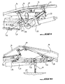
- FIGS 7 to 10 represent, in perspective, different views of an embodiment of the bed base of the invention.
- the bed base 10 of the invention therefore comprises, for the purposes of the invention, a first drive means 21 for tilting the portion 14 for the thighs and a second drive means 22 for tilting the portion 15 for the legs.
- the originality of the provisions of the present invention lies firstly in the fact that these two drive means are shaped to raise, that is to say, incline uphill, the two parts 14, 15 respectively for the thighs and for the legs using a single driving source 21.
- the rotational force generated by this driving source 21 is transmitted on the portion 14 for the thighs by an axis of rotation 25 to which the portion 14 is connected by arms articulated 23, 24.
- the portion 14 then drives, by its movement, the portion 15 for the legs which is articulated on the portion 14 by means of the pivot axis P2.
- the originality of the invention furthermore consists in the fact that the second drive means 22, whose length is adjustable and which is articulated on both the axis 25 and the part 15 for the legs, retains a constant length during this lifting parts 14, 15.
- the parts 14, 15 and the second drive means 22 evolve together so that, seen from the side the two initially flat portions 14, 15 form two adjacent sides of a triangle whose upper corner, represented by the axis P2, rises more and more above the third side represented by the means 22.
- a single driving source is sufficient to tilt the two parts 14, 15 in a manner adapted to the possible movements of the legs of a user of the bed and in particular adapted to folding of this user's knees.
- FIGS. 7 to 10 represent an embodiment of a bed according to the invention comprising a bed base according to the invention, as described above.
- the bed is represented on Figures 7 to 10 as a stationary bed with a support 30 formed essentially by two sections 31, 32 constituting longitudinal members of the support, as well as four adjustable feet 33 through which the support 30 rests on the ground 40.
- the portion 14 is hinged to the central portion 11 and is mounted, by means of two pairs of connecting rods 23, 24 on an axis 25 which is it is pivotally mounted in bearings 34 integral with the two longitudinal members 31, 32.
- the axis 25 is pivotally driven by the drive means 21, for example an electric motor, hydraulic or pneumatic.
- the drive means 22 for the part 15, made in the form of an electric jack, are mounted integral in rotation on the axis 25.
- the movable part of the jack 22 is attached, in an articulated manner, by a connecting rod 26, on the part 15 of the bed base of the invention.
- the cylinder 22 is hung both on the side of the portion 14 that the portion 15 by arcuate fasteners, so that the rod of the cylinder 22 is disposed in a plane substantially parallel to that which form the parts 14 and 15 when the bed extends flat.
- This substantially parallel arrangement allows, when only the drive means 21 is actuated, to rotate the leg portion 15 with a delay relative to the pivoting of the portion 14 for the thighs to obtain, for these two parts, inclinations ensuring not only a certain comfort for the user of the bed, but to ensure otherwise even a clinically necessary positioning, because it is necessary to avoid keeping the leg completely straight.
- the provisions of the invention can transform the bed frame, and thus the bed, chair.
- the driving means is actuated so that the portion 15 for the legs is inclined towards the ground, the portion 14 for the thighs being raised or not, and the drive means are also actuated for the parts 12, 13 respectively for the back and for the head.
- the design of the bed base of the invention and in particular the arrangement of the drive means of the two parts 14, 15 respectively for the thighs and the legs is also particularly suitable for producing a bed according to which the part 14 for the thighs and 15 for the legs are divided into two independent parts along the length of the bed in order to vary the position of the two parts 14, 15 individually for each of the two legs of a bed user.
- FIGS. 11 to 14 schematically represent a truncated support 30 to form a bed and the arrangement of the bed base 10 on this support.
- the support 30 comprises a truncated frame 35 which comprises the longitudinal members 31, 32 interconnected by cross members and which is held at a predetermined height above the ground 40 by four adjustable feet 33 resting on a base 36.
- the base 36 is formed essentially by U-shaped profiles and extended in the direction of the footboard by a plate 37.
- the plate 37 essentially fulfills two roles. The first is to provide a means of stabilization or protection tilting of the bed in case someone sits on the bed frame 10 on the side of the footboard.
- the base 36 extends over at least the entire length of the bed base 10 and is preferably even longer than this.
- the second role is that of presenting to a user of the bed an exit surface when he has turned the bed into a chair and wants to get out of the chair.
- the presence of a tray then prevents the user of the chair stumbles on profiles that would serve instead of the tray as bed stabilizer.
- edges of the plate 37 are advantageously made bevel.
- the base 36 has no stabilizing plate, but is shaped to be fixed to the ground, for example by means of lag bolts 38, to the right of the headboard to take any tilting efforts in case someone sits on the footboard.
- the base includes a counterweight 39 to balance an overload acting at the foot of the bed when someone sits on the footboard.
- the figure 15 represents finally, in a perspective view, an embodiment of a bedding furniture using the bed base 10 of the invention.
- the example shown is a convertible sofa with two places.
- This sofa has two bed bases 10 allowing two people using this sofa to adjust the inclination of the parts 14, 15 respectively for the thighs and for the legs independently of one another, or even to transform only one of the sommiers in armchair.
- the Tray can serve as a base for accessories such as a column stand for a TV receiver.
Landscapes
- Health & Medical Sciences (AREA)
- General Health & Medical Sciences (AREA)
- Nursing (AREA)
- Invalid Beds And Related Equipment (AREA)
Claims (9)
- Ausklappbarer Bettrahmen (10), der mindestens vier Teile aufweist, davon ein nicht verstellbares Mittelteil (11) und mindestens ein verstellbares Teil (12, 13) für den Rücken und den Kopf, ein verstellbares Teil (14) für die Oberschenkel und ein verstellbares Teil (15) für die Unterschenkel, wobei die verstellbaren Teile (12 bis 15) schwenkbar um querliegende Schwenkachsen (P1 bis P4) montiert sind, und mindestens Antriebsmittel (21, 22), die dazu bestimmt sind, auf Befehl die verstellbaren Teile (14, 15) für die Oberschenkel und für die Unterschenkel zu verstellen,
wobei die Antriebsmittel (21, 22) zum Verstellen der Teile für die Oberschenkel (14) und für die Unterschenkel (15) eine gemeinsame Antriebsquelle (21) aufweisen, mit der der Teil für die Oberschenkel (14) und der Teil für die Unterschenkel (15) derart verbunden sind, dass der Verstellung des Teils für die Unterschenkel nicht notwendigerweise der Verstellung des Teils (14) für die Oberschenkel folgt und dass der Teil (15) für die Unterschenkel unter eine Ebene führbar ist, die von dem nicht verstellbaren Mittelteil (11) definiert ist, damit der Bettrahmen in Sesselposition führbar ist, wobei das Antriebsmittel (22), das dazu bestimmt ist, den Teil (15) für die Oberschenkel zu verstellen, mit einer Rotationsachse (25) verbunden ist, dadurch gekennzeichnet, dass diese Rotationsachse (25) des Bettrahmens direkt von dem Antriebsmittel (21) angetrieben wird, das dazu bestimmt ist, den Teil (14) für die Oberschenkel zu verstellen. - Bettrahmen nach Anspruch 1, dadurch gekennzeichnet, dass das Antriebsmittel (22), das dazu bestimmt ist, auf den Teil (15) für die Unterschenkel einzuwirken, ein ausrückbares Element mit einstellbarer Länge aufweist.
- Bettrahmen nach Anspruch 1 oder 2, dadurch gekennzeichnet, dass die Antriebsmittel (21, 22) ausgebildet sind, damit, wenn der Teil (14) für die Oberschenkel aus der horizontalen Position verstellt ist, der Teil (15) für die Oberschenkel zunächst der Verstellung des Teils (14) für die Oberschenkel zu folgen scheint und schrittweise durch umgekehrte Rotation um die querliegende Rotationsachse (P2), mit der der Teil (15) für die Unterschenkel an dem Teil (14) für die Oberschenkel angelenkt ist, zurückbleibt.
- Bettrahmen nach einem der Ansprüche 1 bis 3, dadurch gekennzeichnet, dass der Teil (15) für die Unterschenkel mit Mitteln (16) ausgestattet ist, um ihm bei einem Kontakt mit einem Boden (40) zu erlauben, über dem Boden zu rollen.
- Bettrahmen nach einem der Ansprüche 1 bis 4, dadurch gekennzeichnet, dass die gemeinsame Antriebsquelle (21) einen Elektromotor aufweist, der im Verhältnis zum Mittelteil (11) in starrer Position montiert ist.
- Bettrahmen nach einem der Ansprüche 1 bis 5, dadurch gekennzeichnet, dass das Antriebsmittel (22) zum Verstellen des Teils (15) für die Unterschenkel einen ausfahrbaren Zylinder aufweist.
- Bettrahmen nach einem der Ansprüche 1 bis 6, dadurch gekennzeichnet, dass der Teil (14) für die Oberschenkel und der Teil (15) für die Unterschenkel gemäß der Länge des Betts in zwei unabhängige Teile geteilt sind, damit die Position der zwei Teile (14, 15) für jedes der zwei Beine eines Benutzers des Betts individuell variierbar ist.
- Bett, das einen Bettrahmen (10) nach einem der Ansprüche 1 bis 7 aufweist und eine Stütze (30), durch die das Bett auf einem Boden (40) ruht und auf der der Bettrahmen (10) montiert ist.
- Bett nach Anspruch 8, dadurch gekennzeichnet, dass die Stütze (30) einen an der Fußseite des Betts verkürzten Rahmen (35) aufweist und dass der Bettrahmen (10) im Verhältnis zur Stütze (30), zumindest der Teil (15) für die Unterschenkel, der über die Stütze (30) hinausragt, überhängend montiert ist.
Applications Claiming Priority (1)
| Application Number | Priority Date | Filing Date | Title |
|---|---|---|---|
| FR0655597A FR2909848B1 (fr) | 2006-12-18 | 2006-12-18 | Sommier de literie deployable et lit comprenant un tel sommier |
Publications (3)
| Publication Number | Publication Date |
|---|---|
| EP2014198A2 EP2014198A2 (de) | 2009-01-14 |
| EP2014198A3 EP2014198A3 (de) | 2011-02-16 |
| EP2014198B1 true EP2014198B1 (de) | 2012-05-16 |
Family
ID=38461153
Family Applications (1)
| Application Number | Title | Priority Date | Filing Date |
|---|---|---|---|
| EP20070291540 Active EP2014198B1 (de) | 2006-12-18 | 2007-12-17 | Ausklappbarer Bettrahmen und Bett, das einen solchen Bettrahmen umfasst |
Country Status (2)
| Country | Link |
|---|---|
| EP (1) | EP2014198B1 (de) |
| FR (1) | FR2909848B1 (de) |
Family Cites Families (5)
| Publication number | Priority date | Publication date | Assignee | Title |
|---|---|---|---|---|
| US4258445A (en) * | 1976-07-15 | 1981-03-31 | Zur Henry C | Beds and adjustable body supporting assemblies |
| DE4422850A1 (de) * | 1994-06-30 | 1996-01-04 | Guntram Erbe | Verstellbarer Einlegerahmen für Bettgestelle |
| FR2791536B1 (fr) * | 1999-03-31 | 2001-06-08 | Bernard Heyward | Systeme permettant l'articulation automatique de support de releve buste, tetiere d'un releve jambes et d'un repose pieds pour fauteuil ou d'un lit par manette unique |
| DE20006994U1 (de) * | 2000-04-15 | 2000-11-02 | Kuchel, Hans Joachim, 24576 Bad Bramstedt | Multifunktionsliege |
| IL138968A0 (en) * | 2000-10-12 | 2001-11-25 | Hollandia Internat | Articulated bed frame |
-
2006
- 2006-12-18 FR FR0655597A patent/FR2909848B1/fr active Active
-
2007
- 2007-12-17 EP EP20070291540 patent/EP2014198B1/de active Active
Also Published As
| Publication number | Publication date |
|---|---|
| FR2909848B1 (fr) | 2009-06-05 |
| EP2014198A2 (de) | 2009-01-14 |
| FR2909848A1 (fr) | 2008-06-20 |
| EP2014198A3 (de) | 2011-02-16 |
Similar Documents
| Publication | Publication Date | Title |
|---|---|---|
| EP1764070B1 (de) | Aufrichtstuhl mit Einstellungsvorrichtung des Fußstützneigungswinkels in stehender Position | |
| EP0699067B1 (de) | Hebevorrichtung für aufstehhilfen von rollstühlen und rollstuhl mit einer solchen vorrichtung | |
| EP2004124B1 (de) | Stuhl mit mehreren stellungen für körperbehinderte benutzer | |
| EP1864637B1 (de) | Sitz mit Senkrecht-Stellvorrichtung und verstellbarer Rückenlehne | |
| FR2483201A1 (fr) | Chaise au dossier inclinable comportant ou non un appui pour jambes mobile | |
| EP0077280B1 (de) | Aufrichtstuhl | |
| EP1488770B1 (de) | Hebestuhl mit automatisch veränderlicher Neigung der Rückenlehne | |
| JP6814449B2 (ja) | 高齢者または肥満者用の電動無重力チェア | |
| EP0231698A1 (de) | Umklappbare Fahrzeugsitze | |
| EP3463242B1 (de) | Stuhl | |
| EP3243492B1 (de) | Rollstuhl zur einnahme einer aufrechten position mit rückwärtig vertikalisierendem und abwärts gerichtetem bewegungsverlauf der fussstütze | |
| FR2898489A1 (fr) | Fauteuil roulant adapte aux escaliers | |
| EP2014198B1 (de) | Ausklappbarer Bettrahmen und Bett, das einen solchen Bettrahmen umfasst | |
| EP0183630A1 (de) | Veränderbarer Sitz | |
| CA2245907A1 (fr) | Fauteuil elevateur motorise | |
| EP2196177B1 (de) | Krankenbett mit Räder und zwei Schieberahmen | |
| WO1994001022A1 (fr) | Literie constituee d'un sommier a dossier relevable et matelas adapte | |
| FR2718621A1 (fr) | Sommier articulé à pivotement et coulissement. | |
| WO2002047513A1 (fr) | Fauteuil multi-positions | |
| WO2018104595A1 (fr) | Dispositif d'appui antérieur pour les membres inférieurs | |
| WO1991005531A1 (fr) | Leve-malade | |
| BE1016142A3 (fr) | Armature de fauteuil siege/couchette pour le reglage motorise d'un dossier. | |
| BE1018603A3 (fr) | Sommier pour un lit. | |
| FR2700934A3 (fr) | Meuble pous s'asseoir ou s'allonger ayant la forme d'une ottomane ou d'un récamier. | |
| FR2586180A1 (fr) | Procede pour realiser un meuble de repos articule et meuble obtenu par le procede |
Legal Events
| Date | Code | Title | Description |
|---|---|---|---|
| PUAI | Public reference made under article 153(3) epc to a published international application that has entered the european phase |
Free format text: ORIGINAL CODE: 0009012 |
|
| AK | Designated contracting states |
Kind code of ref document: A2 Designated state(s): AT BE BG CH CY CZ DE DK EE ES FI FR GB GR HU IE IS IT LI LT LU LV MC MT NL PL PT RO SE SI SK TR |
|
| AX | Request for extension of the european patent |
Extension state: AL BA HR MK RS |
|
| PUAL | Search report despatched |
Free format text: ORIGINAL CODE: 0009013 |
|
| AK | Designated contracting states |
Kind code of ref document: A3 Designated state(s): AT BE BG CH CY CZ DE DK EE ES FI FR GB GR HU IE IS IT LI LT LU LV MC MT NL PL PT RO SE SI SK TR |
|
| AX | Request for extension of the european patent |
Extension state: AL BA HR MK RS |
|
| RIC1 | Information provided on ipc code assigned before grant |
Ipc: A47C 20/04 20060101AFI20081205BHEP |
|
| 17P | Request for examination filed |
Effective date: 20110811 |
|
| AKX | Designation fees paid |
Designated state(s): AT BE BG CH CY LI |
|
| GRAP | Despatch of communication of intention to grant a patent |
Free format text: ORIGINAL CODE: EPIDOSNIGR1 |
|
| RIC1 | Information provided on ipc code assigned before grant |
Ipc: A47C 20/04 20060101AFI20111027BHEP Ipc: A47C 20/08 20060101ALI20111027BHEP |
|
| REG | Reference to a national code |
Ref country code: DE Ref legal event code: R108 Ref document number: 602007022637 Country of ref document: DE Effective date: 20111019 Ref country code: DE Ref legal event code: R108 Effective date: 20111019 |
|
| RBV | Designated contracting states (corrected) |
Designated state(s): AT BE BG CH CY CZ DE DK EE ES FI FR GB GR HU IE IS IT LI LT LU LV MC MT NL PL PT RO SE SI SK TR |
|
| GRAS | Grant fee paid |
Free format text: ORIGINAL CODE: EPIDOSNIGR3 |
|
| GRAA | (expected) grant |
Free format text: ORIGINAL CODE: 0009210 |
|
| AK | Designated contracting states |
Kind code of ref document: B1 Designated state(s): AT BE BG CH CY CZ DE DK EE ES FI FR GB GR HU IE IS IT LI LT LU LV MC MT NL PL PT RO SE SI SK TR |
|
| REG | Reference to a national code |
Ref country code: GB Ref legal event code: FG4D Free format text: NOT ENGLISH |
|
| REG | Reference to a national code |
Ref country code: CH Ref legal event code: EP |
|
| REG | Reference to a national code |
Ref country code: AT Ref legal event code: REF Ref document number: 557617 Country of ref document: AT Kind code of ref document: T Effective date: 20120615 |
|
| REG | Reference to a national code |
Ref country code: IE Ref legal event code: FG4D Free format text: LANGUAGE OF EP DOCUMENT: FRENCH |
|
| REG | Reference to a national code |
Ref country code: DE Ref legal event code: R096 Ref document number: 602007022637 Country of ref document: DE Effective date: 20120712 |
|
| REG | Reference to a national code |
Ref country code: NL Ref legal event code: VDEP Effective date: 20120516 |
|
| REG | Reference to a national code |
Ref country code: LT Ref legal event code: MG4D Effective date: 20120516 |
|
| PG25 | Lapsed in a contracting state [announced via postgrant information from national office to epo] |
Ref country code: CY Free format text: LAPSE BECAUSE OF FAILURE TO SUBMIT A TRANSLATION OF THE DESCRIPTION OR TO PAY THE FEE WITHIN THE PRESCRIBED TIME-LIMIT Effective date: 20120516 Ref country code: FI Free format text: LAPSE BECAUSE OF FAILURE TO SUBMIT A TRANSLATION OF THE DESCRIPTION OR TO PAY THE FEE WITHIN THE PRESCRIBED TIME-LIMIT Effective date: 20120516 Ref country code: PL Free format text: LAPSE BECAUSE OF FAILURE TO SUBMIT A TRANSLATION OF THE DESCRIPTION OR TO PAY THE FEE WITHIN THE PRESCRIBED TIME-LIMIT Effective date: 20120516 Ref country code: LT Free format text: LAPSE BECAUSE OF FAILURE TO SUBMIT A TRANSLATION OF THE DESCRIPTION OR TO PAY THE FEE WITHIN THE PRESCRIBED TIME-LIMIT Effective date: 20120516 Ref country code: IS Free format text: LAPSE BECAUSE OF FAILURE TO SUBMIT A TRANSLATION OF THE DESCRIPTION OR TO PAY THE FEE WITHIN THE PRESCRIBED TIME-LIMIT Effective date: 20120916 Ref country code: SE Free format text: LAPSE BECAUSE OF FAILURE TO SUBMIT A TRANSLATION OF THE DESCRIPTION OR TO PAY THE FEE WITHIN THE PRESCRIBED TIME-LIMIT Effective date: 20120516 |
|
| REG | Reference to a national code |
Ref country code: AT Ref legal event code: MK05 Ref document number: 557617 Country of ref document: AT Kind code of ref document: T Effective date: 20120516 |
|
| PG25 | Lapsed in a contracting state [announced via postgrant information from national office to epo] |
Ref country code: PT Free format text: LAPSE BECAUSE OF FAILURE TO SUBMIT A TRANSLATION OF THE DESCRIPTION OR TO PAY THE FEE WITHIN THE PRESCRIBED TIME-LIMIT Effective date: 20120917 Ref country code: SI Free format text: LAPSE BECAUSE OF FAILURE TO SUBMIT A TRANSLATION OF THE DESCRIPTION OR TO PAY THE FEE WITHIN THE PRESCRIBED TIME-LIMIT Effective date: 20120516 Ref country code: GR Free format text: LAPSE BECAUSE OF FAILURE TO SUBMIT A TRANSLATION OF THE DESCRIPTION OR TO PAY THE FEE WITHIN THE PRESCRIBED TIME-LIMIT Effective date: 20120817 Ref country code: LV Free format text: LAPSE BECAUSE OF FAILURE TO SUBMIT A TRANSLATION OF THE DESCRIPTION OR TO PAY THE FEE WITHIN THE PRESCRIBED TIME-LIMIT Effective date: 20120516 |
|
| PG25 | Lapsed in a contracting state [announced via postgrant information from national office to epo] |
Ref country code: CZ Free format text: LAPSE BECAUSE OF FAILURE TO SUBMIT A TRANSLATION OF THE DESCRIPTION OR TO PAY THE FEE WITHIN THE PRESCRIBED TIME-LIMIT Effective date: 20120516 Ref country code: DK Free format text: LAPSE BECAUSE OF FAILURE TO SUBMIT A TRANSLATION OF THE DESCRIPTION OR TO PAY THE FEE WITHIN THE PRESCRIBED TIME-LIMIT Effective date: 20120516 Ref country code: RO Free format text: LAPSE BECAUSE OF FAILURE TO SUBMIT A TRANSLATION OF THE DESCRIPTION OR TO PAY THE FEE WITHIN THE PRESCRIBED TIME-LIMIT Effective date: 20120516 Ref country code: AT Free format text: LAPSE BECAUSE OF FAILURE TO SUBMIT A TRANSLATION OF THE DESCRIPTION OR TO PAY THE FEE WITHIN THE PRESCRIBED TIME-LIMIT Effective date: 20120516 Ref country code: EE Free format text: LAPSE BECAUSE OF FAILURE TO SUBMIT A TRANSLATION OF THE DESCRIPTION OR TO PAY THE FEE WITHIN THE PRESCRIBED TIME-LIMIT Effective date: 20120516 Ref country code: NL Free format text: LAPSE BECAUSE OF FAILURE TO SUBMIT A TRANSLATION OF THE DESCRIPTION OR TO PAY THE FEE WITHIN THE PRESCRIBED TIME-LIMIT Effective date: 20120516 Ref country code: SK Free format text: LAPSE BECAUSE OF FAILURE TO SUBMIT A TRANSLATION OF THE DESCRIPTION OR TO PAY THE FEE WITHIN THE PRESCRIBED TIME-LIMIT Effective date: 20120516 |
|
| PG25 | Lapsed in a contracting state [announced via postgrant information from national office to epo] |
Ref country code: IT Free format text: LAPSE BECAUSE OF FAILURE TO SUBMIT A TRANSLATION OF THE DESCRIPTION OR TO PAY THE FEE WITHIN THE PRESCRIBED TIME-LIMIT Effective date: 20120516 |
|
| PLBE | No opposition filed within time limit |
Free format text: ORIGINAL CODE: 0009261 |
|
| STAA | Information on the status of an ep patent application or granted ep patent |
Free format text: STATUS: NO OPPOSITION FILED WITHIN TIME LIMIT |
|
| 26N | No opposition filed |
Effective date: 20130219 |
|
| PG25 | Lapsed in a contracting state [announced via postgrant information from national office to epo] |
Ref country code: ES Free format text: LAPSE BECAUSE OF FAILURE TO SUBMIT A TRANSLATION OF THE DESCRIPTION OR TO PAY THE FEE WITHIN THE PRESCRIBED TIME-LIMIT Effective date: 20120827 |
|
| REG | Reference to a national code |
Ref country code: DE Ref legal event code: R097 Ref document number: 602007022637 Country of ref document: DE Effective date: 20130219 |
|
| BERE | Be: lapsed |
Owner name: LA CIE CONTINENTALE SIMMONS Effective date: 20121231 |
|
| PG25 | Lapsed in a contracting state [announced via postgrant information from national office to epo] |
Ref country code: BG Free format text: LAPSE BECAUSE OF FAILURE TO SUBMIT A TRANSLATION OF THE DESCRIPTION OR TO PAY THE FEE WITHIN THE PRESCRIBED TIME-LIMIT Effective date: 20120816 Ref country code: MC Free format text: LAPSE BECAUSE OF NON-PAYMENT OF DUE FEES Effective date: 20121231 |
|
| REG | Reference to a national code |
Ref country code: CH Ref legal event code: PL |
|
| GBPC | Gb: european patent ceased through non-payment of renewal fee |
Effective date: 20121217 |
|
| REG | Reference to a national code |
Ref country code: IE Ref legal event code: MM4A |
|
| PG25 | Lapsed in a contracting state [announced via postgrant information from national office to epo] |
Ref country code: BE Free format text: LAPSE BECAUSE OF NON-PAYMENT OF DUE FEES Effective date: 20121231 |
|
| REG | Reference to a national code |
Ref country code: DE Ref legal event code: R119 Ref document number: 602007022637 Country of ref document: DE Effective date: 20130702 |
|
| PG25 | Lapsed in a contracting state [announced via postgrant information from national office to epo] |
Ref country code: LI Free format text: LAPSE BECAUSE OF NON-PAYMENT OF DUE FEES Effective date: 20121231 Ref country code: DE Free format text: LAPSE BECAUSE OF NON-PAYMENT OF DUE FEES Effective date: 20130702 Ref country code: IE Free format text: LAPSE BECAUSE OF NON-PAYMENT OF DUE FEES Effective date: 20121217 Ref country code: CH Free format text: LAPSE BECAUSE OF NON-PAYMENT OF DUE FEES Effective date: 20121231 |
|
| PG25 | Lapsed in a contracting state [announced via postgrant information from national office to epo] |
Ref country code: GB Free format text: LAPSE BECAUSE OF NON-PAYMENT OF DUE FEES Effective date: 20121217 Ref country code: MT Free format text: LAPSE BECAUSE OF FAILURE TO SUBMIT A TRANSLATION OF THE DESCRIPTION OR TO PAY THE FEE WITHIN THE PRESCRIBED TIME-LIMIT Effective date: 20120516 |
|
| PG25 | Lapsed in a contracting state [announced via postgrant information from national office to epo] |
Ref country code: TR Free format text: LAPSE BECAUSE OF FAILURE TO SUBMIT A TRANSLATION OF THE DESCRIPTION OR TO PAY THE FEE WITHIN THE PRESCRIBED TIME-LIMIT Effective date: 20120516 |
|
| PG25 | Lapsed in a contracting state [announced via postgrant information from national office to epo] |
Ref country code: LU Free format text: LAPSE BECAUSE OF NON-PAYMENT OF DUE FEES Effective date: 20121217 |
|
| PG25 | Lapsed in a contracting state [announced via postgrant information from national office to epo] |
Ref country code: HU Free format text: LAPSE BECAUSE OF FAILURE TO SUBMIT A TRANSLATION OF THE DESCRIPTION OR TO PAY THE FEE WITHIN THE PRESCRIBED TIME-LIMIT Effective date: 20071217 |
|
| REG | Reference to a national code |
Ref country code: FR Ref legal event code: PLFP Year of fee payment: 9 |
|
| REG | Reference to a national code |
Ref country code: FR Ref legal event code: PLFP Year of fee payment: 10 |
|
| REG | Reference to a national code |
Ref country code: FR Ref legal event code: PLFP Year of fee payment: 11 |
|
| PGFP | Annual fee paid to national office [announced via postgrant information from national office to epo] |
Ref country code: FR Payment date: 20251215 Year of fee payment: 19 |