EP2014990A1 - Dispositif de commande pour appareils ménagers - Google Patents
Dispositif de commande pour appareils ménagers Download PDFInfo
- Publication number
- EP2014990A1 EP2014990A1 EP08104516A EP08104516A EP2014990A1 EP 2014990 A1 EP2014990 A1 EP 2014990A1 EP 08104516 A EP08104516 A EP 08104516A EP 08104516 A EP08104516 A EP 08104516A EP 2014990 A1 EP2014990 A1 EP 2014990A1
- Authority
- EP
- European Patent Office
- Prior art keywords
- control panel
- operating device
- domestic appliance
- appliance operating
- control
- Prior art date
- Legal status (The legal status is an assumption and is not a legal conclusion. Google has not performed a legal analysis and makes no representation as to the accuracy of the status listed.)
- Granted
Links
Images


Classifications
-
- F—MECHANICAL ENGINEERING; LIGHTING; HEATING; WEAPONS; BLASTING
- F24—HEATING; RANGES; VENTILATING
- F24C—DOMESTIC STOVES OR RANGES ; DETAILS OF DOMESTIC STOVES OR RANGES, OF GENERAL APPLICATION
- F24C7/00—Stoves or ranges heated by electric energy
- F24C7/08—Arrangement or mounting of control or safety devices
- F24C7/082—Arrangement or mounting of control or safety devices on ranges, e.g. control panels, illumination
-
- A—HUMAN NECESSITIES
- A47—FURNITURE; DOMESTIC ARTICLES OR APPLIANCES; COFFEE MILLS; SPICE MILLS; SUCTION CLEANERS IN GENERAL
- A47L—DOMESTIC WASHING OR CLEANING; SUCTION CLEANERS IN GENERAL
- A47L15/00—Washing or rinsing machines for crockery or tableware
- A47L15/42—Details
- A47L15/4293—Arrangements for programme selection, e.g. control panels; Indication of the selected programme, programme progress or other parameters of the programme, e.g. by using display panels
-
- D—TEXTILES; PAPER
- D06—TREATMENT OF TEXTILES OR THE LIKE; LAUNDERING; FLEXIBLE MATERIALS NOT OTHERWISE PROVIDED FOR
- D06F—LAUNDERING, DRYING, IRONING, PRESSING OR FOLDING TEXTILE ARTICLES
- D06F34/00—Details of control systems for washing machines, washer-dryers or laundry dryers
- D06F34/28—Arrangements for program selection, e.g. control panels therefor; Arrangements for indicating program parameters, e.g. the selected program or its progress
Definitions
- the invention relates to a household appliance operating device according to the preamble of claim 1.
- the object of the invention is, in particular, to provide a generic device which is advantageously operable.
- the object is achieved by the features of the independent claims, while advantageous embodiments and modifications of the invention can be taken from the dependent claims.
- the invention is based on a domestic appliance operating device with a control panel and a control panel.
- control panel terminate in at least one area at least substantially with an upper and / or a lower outer edge of the control panel.
- a “control panel” is to be understood as a cover and / or in particular a front part of a domestic appliance in which a control panel is integrated with control elements and in particular has one or more recesses for control elements of a control panel.
- a “control element” can be formed by various elements that appear appropriate to a person skilled in the art, such as, in particular, a control knob or particularly advantageously an operator control key, etc.
- a “control panel” is to be understood as meaning, in particular, a field with associated control elements, the togetherness being understood can result from an operating logic and / or a spatial arrangement.
- a maximum distance between directly adjacent control elements is less than 5 cm and particularly advantageously less than 2 cm.
- an "outer edge” should also be understood to mean an edge limiting the control panel to the outside, in particular laterally next to it the control panel is arranged, and it is to be excluded an edge of a fully enclosed by the control panel recess.
- "essentially” in this context should be understood in particular to mean that the control panel has a distance to an upper and / or lower outer edge of less than 5% and advantageously less than 1% of a height of the control panel in this area and particularly advantageously none Distance has.
- the individual controls can be advantageously carried out large despite a clear overall structure, and in particular when the control panel has at least two successively arranged one above the other or in the direction of a vertical extent, substantially immediately adjoining controls.
- substantially immediately adjacent to one another is to be understood in particular that the operating elements in the direction of the vertical extent have a distance of less than 10 mm, advantageously less than 5 mm and particularly advantageously less than 2 mm.
- control panel in at least one area has a height less than 100 mm and advantageously less than 80 mm and particularly advantageously has a height between 70 mm and 50 mm.
- a "height" is to be understood as meaning, in particular, a front surface height formed by the control panel, which extends in particular in the vertical direction.
- the household appliance operating device has a one-piece user interface means, which forms at least part of a user interface of a first operating element and a second operating element.
- the user interface means may be formed by various means that appear appropriate to those skilled in the art, but particularly advantageous from a control film that can be simple, inexpensive and robust.
- the household appliance operating device has at least one control element arranged in the control panel with a symbol whose width extends at least over 80% of a control element width of the control element and / or its height at least over 80% of a control element height of the control element , whereby the clarity can be further improved and the operation can be further simplified, in particular if at least a large part of the controls has corresponding symbols.
- the domestic appliance operating device has a display arranged above the control panel, an operation can advantageously be supported by the display, and a concealment of the display by an operator even during an operation can be avoided.
- the display may have a length which is less than or equal to a length of the control panel or particularly advantageous, which is longer than a length of the control panel.
- control panel has at least two, preferably at least three and more preferably at least four control elements arranged one behind the other in a reading direction, which are to be actuated successively according to their arrangement in the reading direction in at least one operating logic.
- a "reading direction” is thereby to be understood in a basic operating position, as understood in particular in a position with a viewing direction substantially perpendicular to a front side from the front, from left to right.
- an "operating logic” is to be understood as meaning, in particular, a sensible and, in particular, recommended sequence of an actuation of operating elements.
- main switch preferably one end of the control panel is formed by a main switch, preferably a left end viewed in a basic operating position.
- a “main switch” should be understood in particular a switch for switching on and / or off.
- the operation can be simplified if the domestic appliance operating device has at least one signal means, which leads to an acknowledgment of an actuation of a control element is provided, and particularly preferably when the signal means is arranged in a surface region of an associated control element.
- the signal means has a slot-shaped configuration and / or if the signal means forms at least part of a frame of a control element, this can be positioned particularly advantageously in a space-saving and easily visible manner.
- a slot-shaped configuration should be understood in particular to mean that the signal means has a width at least three times and preferably at least five times greater than the width.
- a "frame” should be understood to mean, in particular, that the signal means limits the operating element laterally, and particularly preferably over at least 30% of its projected circumference. If the signal means forms a guide of a control element, additional components, installation space, installation effort and costs can be saved.
- the signal means is at least partially formed integrally with a sensor means, whereby further additional components, space, assembly costs and costs can be saved.
- a "side frame” should be understood to mean, in particular, a frame that laterally delimits the appliance door in a horizontal direction parallel to a front side.
- main program operating elements in cooking device operating devices is understood to mean heating element operating elements for selecting different heating elements, such as top heat, bottom heat, circulating air, grill and combinations thereof, in particular dishwashing program operating elements for selecting different washing programs and washing machine operating devices for selecting different washing programs.
- Fig. 1 shows a front view of a cooking appliance shown schematically with a cooking appliance operating device.
- the cooking appliance operating device comprises an H-shaped control panel 10a made of stainless steel with a transverse leg 50a with an integrated control panel 14a and two vertically extending legs 52a, 54a, which form a side frame of a household appliance door 48a of the cooking appliance or limit the appliance door 48a laterally.
- the transverse leg 50a of the control panel 10a has a height 12a of about 60 mm.
- the control panel 14a has the same height as the transverse leg 50a and closes over its entire length with a lower outer edge 16a and an upper outer edge 18a of the transverse leg 50a, whereby controls 20a - 28a are particularly large and easily optically and tactile detectable by an operator can be.
- the control panel 14a has the horizontal direction in a reading direction 44a from left to right successively arranged controls 20a - 28a, which are to operate according to the arrangement from left to right in a recommended operating logic sequentially.
- a left end of the control panel 14a is formed by the operating element 20a designed as an operating button, which extends over the entire height 12a of the control panel 10a and forms a main switch for switching the cooking appliance on and off.
- the operating element 20a is followed directly in the reading direction 44a by a functional block with the four operating elements 22a in the form of operating keys, which are arranged directly adjacent to one another in two rows and which are arranged next to one another immediately adjacent to one another in two rows.
- the operating elements 22a of the functional block form main program operating elements which are intended to select different types of heating, in the present case the type of heating combined with lower heat and upper heat, combined circulating air, grill and grill with circulating air.
- the operating block is followed by the operating element 24a formed by a rotary knob, which is provided in particular for setting a temperature.
- the operating element 24a is followed, in the reading direction 44a, by an operating block with the four operating elements 26a designed as operating keys, by means of which an alarm time or a time can be set up to an alarm, a time, an oven duration and an end time.
- the operating elements 26a are arranged adjacent to one another and directly adjacent to one another in two rows corresponding to the operating elements 22a in two rows.
- the operator control element 26a is adjoined by the operating element 28a in the reading direction 44a, which is intended to start a selected process and which extends in accordance with the operating element 20a over the entire height 12a of the control panel 10a.
- the operating element 28a forms the right end of the control panel 14a.
- the cooking appliance is first switched on at the control element 20a, then a corresponding type of heating is selected via the control elements 22a of the function block. Subsequently, a corresponding temperature is set on the operating element 24a, a baking time is set by means of the operating elements 26a of the operating block, and then the selected process is started by means of the operating element 28a.
- a strip-shaped display 42a is arranged, which has the same length as the transverse leg 50a and laterally extends beyond the control panel 14a due to its greater length relative to the control panel 14a.
- the display 42a is particularly intended to display selected types of heating by means of a text and by means of a symbol.
- the cooking appliance operating device comprises signaling means 46a, which are provided for acknowledging an actuation of the operating elements 20a, 22a, 26a, 28a ( FIG. 2 ).
- Each signal means 46a is arranged in a surface area of an associated control element 20a-28a.
- the signal means 46a are slit-shaped and integrally formed with sensor means, in that they are intended to transmit a sensor radiation, namely by being made permeable to sensor beams formed by infrared radiation. In the operated controls 20a, 22a, 26a, 28a visible light is emitted via the signal means 46a to the outside.
- the operating elements 20a, 22a, 26a, 28a each have symbols 32a, 34a, 38a, 40a which each extend over approximately 90% of a control element width 70a.
- the signal means 46a is arranged within the symbol 32a, while in the operating elements 22a, 26a, 28a the signal means 46a are respectively arranged in the area of the operating elements 22a, 26a, 28a immediately below the symbols 34a, 38a, 40a.
- FIGS. 2 to 7 Alternative embodiments are shown. Substantially identical components, features and functions are basically numbered by the same reference numerals. To distinguish the embodiments, however, the reference numerals of the embodiments, the letters a to e are added. The following description is essentially limited to the differences from the embodiment in FIG. 1 , wherein with respect to the same components, features and functions on the description of the embodiment in FIG. 1 can be referenced.
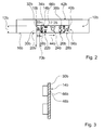
- FIG. 2 an alternative cooking appliance operating device is shown with a U-shaped control panel 10b.
- a control panel 14b is integrated, which has the same length as the transverse leg 56b.
- the transverse leg 56b of the control panel 10b has approximately a height 12b of 60 mm.
- a display 42b Above of the control panel 14b is arranged a display 42b, which has the same length as the transverse leg 56b or as the control panel 14b.
- the control panel 14b has a one-piece control surface means 30b which, except for a control element 24b formed by a rotary knob, forms a control surface 66b for all control elements 20b, 22b, 26b, 28b, on which symbols 32b, 34b, 38b, 40b are arranged.
- the user interface means 30b is formed by a control film ( FIG. 3 ).
- a control element width 70b is thereby formed by a respective symbol width and a control element height of a respective symbol height itself.
- the visible surface means 30b has transparent, slit-shaped portions for visible light and for a sensor beam, namely for infrared rays, which form signaling means 46b for acknowledging an actuation of the operating elements 20b, 22b, 26b, 28b, in surface areas of the respective operating elements 20b, 22b. 26b, 28b are arranged and formed integrally with sensor means of the cooking appliance operating device.
- the user interface means could alternatively and / or additionally be formed by a touch-sensitive means and / or also by a control panel itself.
- control elements 20b, 22b and the control elements 26b, 28b connect directly, seamlessly to each other, whereby an advantageous clarity and an advantageous cleaning option can be achieved.
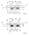
- FIG. 4 an alternative cooking appliance operating device is shown with a strip-shaped control panel 10c.
- a display 42c arranged above the control panel 10c has the same length as the control panel 10c.
- FIG. 5 an alternative Garellabedienvorraum is shown with a strip-shaped control panel 10d and a display 42d, which except for specially trained signal means 46d substantially the cooking appliance operating device FIG. 4 equivalent.
- the signal means 46d provided for acknowledging an actuation of operating elements 20d, 22d, 26d, 28d respectively form a frame and a guide for the operating elements 20d, 22d, 26d, 28d of the cooking appliance operating device ( FIG. 6 ).
- the signal means 46b extend laterally under the control panel 10d and in the present embodiment in particular an L-shaped frame profile.
- the Signaling means 46d are light-emitting means 58d, namely light-emitting diodes, arranged.
- the signal means 46d are designed as light guides, so that light emitted by the light sources 58d can be forwarded within the signal means 46d by a deflection angle 60d, in the present case by a deflection angle of 90 °.
- the operating elements 20d, 22d, 26d, 28d comprise lifting keys 68d, which have the same material on their front side as the operating panel 10d, namely, the lifting keys 68d are provided on their front side with a material layer 64d.
- the material layer 64d and the control panel 10d are made of stainless steel.
- FIG. 7 a cooking appliance with an alternative cooking appliance operating device is shown, which has a U-shaped control panel 10e and a substantially U-shaped control panel 14e.
- the control panel 10e has a total height 12e of about 60 mm and in the region of its transverse leg 56e a height 12e 'of about 30 mm. Above the transverse leg 56e, a display 42e is arranged.
- the control panel 14e has control elements 26e, 24e arranged directly next to one another on the left and right next to the display 42e, and control elements 26e arranged side by side in a row next to one another as control buttons underneath the display 42e.
- the operating elements 24e for setting a temperature are also embodied as operating keys with symbols 36e, and a functional block has, in comparison with the exemplary embodiments in FIGS FIGS. 1 to 6 six main program controls forming controls 22e, which are intended to select types of heating, in the present case, the types of heating bottom heat combined with top heat, thawing, convection, grill and grill combined with circulating air and self-cleaning.
- the operating elements 20e, 26e, 28e terminate in each case with an upper and with a lower outer edge 16e, 18e, 18e 'of the operating panel 10e, while the operating elements 22e, 24e, 26e' respectively with the upper or the lower outer edge 16e, 18e of the control panel Complete 10e.
Landscapes
- Engineering & Computer Science (AREA)
- Chemical & Material Sciences (AREA)
- Combustion & Propulsion (AREA)
- Mechanical Engineering (AREA)
- General Engineering & Computer Science (AREA)
- Push-Button Switches (AREA)
- Electric Stoves And Ranges (AREA)
- Cookers (AREA)
Priority Applications (1)
| Application Number | Priority Date | Filing Date | Title |
|---|---|---|---|
| PL08104516T PL2014990T3 (pl) | 2007-07-09 | 2008-06-24 | Urządzenie do obróbki termicznej z urządzeniem obsługowym urządzenia do obróbki termicznej |
Applications Claiming Priority (1)
| Application Number | Priority Date | Filing Date | Title |
|---|---|---|---|
| DE102007031885A DE102007031885A1 (de) | 2007-07-09 | 2007-07-09 | Hausgerätebedienvorrichtung |
Publications (2)
| Publication Number | Publication Date |
|---|---|
| EP2014990A1 true EP2014990A1 (fr) | 2009-01-14 |
| EP2014990B1 EP2014990B1 (fr) | 2020-08-26 |
Family
ID=39917660
Family Applications (1)
| Application Number | Title | Priority Date | Filing Date |
|---|---|---|---|
| EP08104516.3A Active EP2014990B1 (fr) | 2007-07-09 | 2008-06-24 | Dispositif de cuisson avec un dispositif de commande |
Country Status (4)
| Country | Link |
|---|---|
| EP (1) | EP2014990B1 (fr) |
| DE (1) | DE102007031885A1 (fr) |
| ES (1) | ES2814248T3 (fr) |
| PL (1) | PL2014990T3 (fr) |
Cited By (1)
| Publication number | Priority date | Publication date | Assignee | Title |
|---|---|---|---|---|
| WO2010112291A3 (fr) * | 2009-03-30 | 2011-02-24 | BSH Bosch und Siemens Hausgeräte GmbH | Dispositif de commande pour un appareil ménager et procédé pour faire fonctionner un appareil ménager au moyen d'un dispositif de commande |
Families Citing this family (2)
| Publication number | Priority date | Publication date | Assignee | Title |
|---|---|---|---|---|
| DE102014212396B4 (de) | 2014-06-27 | 2022-09-29 | BSH Hausgeräte GmbH | Haushaltsgerät mit einer perforierten Gerätekomponente |
| DE102021000885A1 (de) | 2021-02-19 | 2022-08-25 | Senay Buruk | Backofen/Herd in Kombination mit KühlfunktionBack-Kühl-KombiKühl-Back-Kombi |
Citations (5)
| Publication number | Priority date | Publication date | Assignee | Title |
|---|---|---|---|---|
| CH678784A5 (en) * | 1989-05-31 | 1991-10-31 | Electrolux Ag | Control panel for electric baking oven - has programme keyboard for accessing and selecting stored cooking programmes |
| DE9405473U1 (de) * | 1994-03-31 | 1994-05-26 | Noth, Winfried, 73525 Schwäbisch Gmünd | Herd |
| EP1569057A2 (fr) * | 2004-02-25 | 2005-08-31 | BSH Bosch und Siemens Hausgeräte GmbH | Champ d'un panneau de commande pour appareil électroménager à commande par programme |
| DE202007002887U1 (de) * | 2007-02-28 | 2007-04-19 | Störk-Tronic, Störk GmbH & Co KG | Bediensystem |
| DE102005049802A1 (de) | 2005-10-18 | 2007-04-19 | BSH Bosch und Siemens Hausgeräte GmbH | Haushaltsgerätebedienvorrichtung |
Family Cites Families (5)
| Publication number | Priority date | Publication date | Assignee | Title |
|---|---|---|---|---|
| US678784A (en) * | 1900-05-12 | 1901-07-16 | Katherine Magner | Neck-marking machine. |
| FR2622681B1 (fr) * | 1987-10-30 | 1990-10-12 | Europ Equip Menager | Dispositif d'affichage et de commande electronique pour des appareils de cuisson domestiques et procede de mise en oeuvre |
| DE29722024U1 (de) * | 1997-12-13 | 1998-04-02 | Platt, Nils, Dipl.-Ing. (FH), 74374 Zaberfeld | Schaltbare Glastüren von Haushaltsgeräten, wie Backofen, Mikrowelle, Kühlschrank und Waschmaschine |
| DE10349675A1 (de) * | 2003-10-24 | 2005-05-25 | BSH Bosch und Siemens Hausgeräte GmbH | Dunstabzugsvorrichtung mit einem Schirm aus transparentem Material |
| DE102004049691A1 (de) * | 2004-10-12 | 2006-04-13 | BSH Bosch und Siemens Hausgeräte GmbH | Bedieneinrichtung |
-
2007
- 2007-07-09 DE DE102007031885A patent/DE102007031885A1/de not_active Withdrawn
-
2008
- 2008-06-24 PL PL08104516T patent/PL2014990T3/pl unknown
- 2008-06-24 EP EP08104516.3A patent/EP2014990B1/fr active Active
- 2008-06-24 ES ES08104516T patent/ES2814248T3/es active Active
Patent Citations (5)
| Publication number | Priority date | Publication date | Assignee | Title |
|---|---|---|---|---|
| CH678784A5 (en) * | 1989-05-31 | 1991-10-31 | Electrolux Ag | Control panel for electric baking oven - has programme keyboard for accessing and selecting stored cooking programmes |
| DE9405473U1 (de) * | 1994-03-31 | 1994-05-26 | Noth, Winfried, 73525 Schwäbisch Gmünd | Herd |
| EP1569057A2 (fr) * | 2004-02-25 | 2005-08-31 | BSH Bosch und Siemens Hausgeräte GmbH | Champ d'un panneau de commande pour appareil électroménager à commande par programme |
| DE102005049802A1 (de) | 2005-10-18 | 2007-04-19 | BSH Bosch und Siemens Hausgeräte GmbH | Haushaltsgerätebedienvorrichtung |
| DE202007002887U1 (de) * | 2007-02-28 | 2007-04-19 | Störk-Tronic, Störk GmbH & Co KG | Bediensystem |
Cited By (1)
| Publication number | Priority date | Publication date | Assignee | Title |
|---|---|---|---|---|
| WO2010112291A3 (fr) * | 2009-03-30 | 2011-02-24 | BSH Bosch und Siemens Hausgeräte GmbH | Dispositif de commande pour un appareil ménager et procédé pour faire fonctionner un appareil ménager au moyen d'un dispositif de commande |
Also Published As
| Publication number | Publication date |
|---|---|
| DE102007031885A1 (de) | 2009-01-15 |
| EP2014990B1 (fr) | 2020-08-26 |
| ES2814248T3 (es) | 2021-03-26 |
| PL2014990T3 (pl) | 2021-04-06 |
Similar Documents
| Publication | Publication Date | Title |
|---|---|---|
| DE112008002807B4 (de) | Kochfeld und Verfahren zum Betreiben eines Kochfelds | |
| EP1338849A1 (fr) | Procédé de traitement et de préparation d'aliments dans un appareil de cuisson, panneau de commande pour appareil de cuisson et appareil de cuisson avec panneau de cuisson | |
| EP2095194A1 (fr) | Dispositif de commande et procédé pour la commande d'un appareil domestique à commande par programme | |
| DE19918290C1 (de) | Kochgerät mit einfach handhabbarer Bedieneinrichtung | |
| DE102005018298A1 (de) | Verfahren zur Ansteuerung und/oder Auswertung eines länglichen Sensorelements einer Bedieneinrichtung und eine solche Bedieneinrichtung | |
| DE102004024835B3 (de) | Sensoranordnung für eine Pseudokontinuierliche Betätigung | |
| EP3612002B1 (fr) | Procédé de commande d'un dispositif de chauffage d'un champ de cuisson et champ de cuisson | |
| EP2026010B1 (fr) | Dispositif de commande d'appareils ménagers | |
| EP2014990B1 (fr) | Dispositif de cuisson avec un dispositif de commande | |
| EP1844265A1 (fr) | Unite de reglage d'appareil domestique | |
| WO2009007291A2 (fr) | Dispositif de commande d'appareil ménager | |
| EP2702922A2 (fr) | Procédé de commande d'un appareil ménager et appareil ménager doté d'un dispositif de commande ergonomique | |
| EP3330617B1 (fr) | Plaque de cuisson et procédé de fonctionnement d'une telle plaque de cuisson | |
| DE102010063983A1 (de) | Hausgerät mit Individualprogrammen | |
| DE3010715A1 (de) | Bedienungstableau | |
| DE102004019329B4 (de) | Geschirrspülmaschine mit optischer Betriebsablaufanzeige | |
| DE19802865A1 (de) | Programmgesteuertes Haushaltgerät mit einer Bedienungshandhabe | |
| DE2723325C2 (de) | Sensorschalter-Einrichtung | |
| DE102005051297A1 (de) | Hausgerät mit einem Bedienelement | |
| DE102019215458A1 (de) | Anzeigevorrichtung für ein Haushaltsgerät, Haushaltsgerät mit Anzeigevorrichtung und Herstellungsverfahren für eine Anzeigevorrichtung | |
| BE1030351B1 (de) | Haushaltsgerät, vorzugsweise Küchengerät, besonders vorzugsweise Kochfeld | |
| DE102005028335A1 (de) | Geschirrspülmaschine | |
| EP3330616B1 (fr) | Plaque de cuisson et procédé de fonctionnement d'une telle plaque de cuisson | |
| DE102023104146A1 (de) | Haushaltsgerät, vorzugsweise Küchengerät, besonders vorzugsweise Kochfeld | |
| DE60117278T2 (de) | Vorrichtung für einen ofen zur verbesserung des einblicks in den ofenraum |
Legal Events
| Date | Code | Title | Description |
|---|---|---|---|
| PUAI | Public reference made under article 153(3) epc to a published international application that has entered the european phase |
Free format text: ORIGINAL CODE: 0009012 |
|
| AK | Designated contracting states |
Kind code of ref document: A1 Designated state(s): AT BE BG CH CY CZ DE DK EE ES FI FR GB GR HR HU IE IS IT LI LT LU LV MC MT NL NO PL PT RO SE SI SK TR |
|
| AX | Request for extension of the european patent |
Extension state: AL BA MK RS |
|
| 17P | Request for examination filed |
Effective date: 20090714 |
|
| 17Q | First examination report despatched |
Effective date: 20090814 |
|
| AKX | Designation fees paid |
Designated state(s): AT BE BG CH CY CZ DE DK EE ES FI FR GB GR HR HU IE IS IT LI LT LU LV MC MT NL NO PL PT RO SE SI SK TR |
|
| RAP1 | Party data changed (applicant data changed or rights of an application transferred) |
Owner name: BSH HAUSGERAETE GMBH |
|
| STAA | Information on the status of an ep patent application or granted ep patent |
Free format text: STATUS: EXAMINATION IS IN PROGRESS |
|
| GRAP | Despatch of communication of intention to grant a patent |
Free format text: ORIGINAL CODE: EPIDOSNIGR1 |
|
| STAA | Information on the status of an ep patent application or granted ep patent |
Free format text: STATUS: GRANT OF PATENT IS INTENDED |
|
| INTG | Intention to grant announced |
Effective date: 20200414 |
|
| RIC1 | Information provided on ipc code assigned before grant |
Ipc: D06F 34/28 20200101ALI20200327BHEP Ipc: A47L 15/42 20060101ALI20200327BHEP Ipc: F24C 7/08 20060101AFI20200327BHEP |
|
| GRAS | Grant fee paid |
Free format text: ORIGINAL CODE: EPIDOSNIGR3 |
|
| GRAA | (expected) grant |
Free format text: ORIGINAL CODE: 0009210 |
|
| STAA | Information on the status of an ep patent application or granted ep patent |
Free format text: STATUS: THE PATENT HAS BEEN GRANTED |
|
| AK | Designated contracting states |
Kind code of ref document: B1 Designated state(s): AT BE BG CH CY CZ DE DK EE ES FI FR GB GR HR HU IE IS IT LI LT LU LV MC MT NL NO PL PT RO SE SI SK TR |
|
| REG | Reference to a national code |
Ref country code: GB Ref legal event code: FG4D Free format text: NOT ENGLISH |
|
| REG | Reference to a national code |
Ref country code: CH Ref legal event code: EP |
|
| REG | Reference to a national code |
Ref country code: DE Ref legal event code: R096 Ref document number: 502008017133 Country of ref document: DE |
|
| REG | Reference to a national code |
Ref country code: AT Ref legal event code: REF Ref document number: 1306741 Country of ref document: AT Kind code of ref document: T Effective date: 20200915 |
|
| REG | Reference to a national code |
Ref country code: IE Ref legal event code: FG4D Free format text: LANGUAGE OF EP DOCUMENT: GERMAN |
|
| REG | Reference to a national code |
Ref country code: LT Ref legal event code: MG4D |
|
| PG25 | Lapsed in a contracting state [announced via postgrant information from national office to epo] |
Ref country code: BG Free format text: LAPSE BECAUSE OF FAILURE TO SUBMIT A TRANSLATION OF THE DESCRIPTION OR TO PAY THE FEE WITHIN THE PRESCRIBED TIME-LIMIT Effective date: 20201126 Ref country code: NO Free format text: LAPSE BECAUSE OF FAILURE TO SUBMIT A TRANSLATION OF THE DESCRIPTION OR TO PAY THE FEE WITHIN THE PRESCRIBED TIME-LIMIT Effective date: 20201126 Ref country code: HR Free format text: LAPSE BECAUSE OF FAILURE TO SUBMIT A TRANSLATION OF THE DESCRIPTION OR TO PAY THE FEE WITHIN THE PRESCRIBED TIME-LIMIT Effective date: 20200826 Ref country code: GR Free format text: LAPSE BECAUSE OF FAILURE TO SUBMIT A TRANSLATION OF THE DESCRIPTION OR TO PAY THE FEE WITHIN THE PRESCRIBED TIME-LIMIT Effective date: 20201127 Ref country code: LT Free format text: LAPSE BECAUSE OF FAILURE TO SUBMIT A TRANSLATION OF THE DESCRIPTION OR TO PAY THE FEE WITHIN THE PRESCRIBED TIME-LIMIT Effective date: 20200826 Ref country code: SE Free format text: LAPSE BECAUSE OF FAILURE TO SUBMIT A TRANSLATION OF THE DESCRIPTION OR TO PAY THE FEE WITHIN THE PRESCRIBED TIME-LIMIT Effective date: 20200826 Ref country code: FI Free format text: LAPSE BECAUSE OF FAILURE TO SUBMIT A TRANSLATION OF THE DESCRIPTION OR TO PAY THE FEE WITHIN THE PRESCRIBED TIME-LIMIT Effective date: 20200826 Ref country code: PT Free format text: LAPSE BECAUSE OF FAILURE TO SUBMIT A TRANSLATION OF THE DESCRIPTION OR TO PAY THE FEE WITHIN THE PRESCRIBED TIME-LIMIT Effective date: 20201228 |
|
| REG | Reference to a national code |
Ref country code: NL Ref legal event code: MP Effective date: 20200826 |
|
| PG25 | Lapsed in a contracting state [announced via postgrant information from national office to epo] |
Ref country code: IS Free format text: LAPSE BECAUSE OF FAILURE TO SUBMIT A TRANSLATION OF THE DESCRIPTION OR TO PAY THE FEE WITHIN THE PRESCRIBED TIME-LIMIT Effective date: 20201226 Ref country code: LV Free format text: LAPSE BECAUSE OF FAILURE TO SUBMIT A TRANSLATION OF THE DESCRIPTION OR TO PAY THE FEE WITHIN THE PRESCRIBED TIME-LIMIT Effective date: 20200826 Ref country code: NL Free format text: LAPSE BECAUSE OF FAILURE TO SUBMIT A TRANSLATION OF THE DESCRIPTION OR TO PAY THE FEE WITHIN THE PRESCRIBED TIME-LIMIT Effective date: 20200826 |
|
| REG | Reference to a national code |
Ref country code: ES Ref legal event code: FG2A Ref document number: 2814248 Country of ref document: ES Kind code of ref document: T3 Effective date: 20210326 |
|
| PG25 | Lapsed in a contracting state [announced via postgrant information from national office to epo] |
Ref country code: CZ Free format text: LAPSE BECAUSE OF FAILURE TO SUBMIT A TRANSLATION OF THE DESCRIPTION OR TO PAY THE FEE WITHIN THE PRESCRIBED TIME-LIMIT Effective date: 20200826 Ref country code: EE Free format text: LAPSE BECAUSE OF FAILURE TO SUBMIT A TRANSLATION OF THE DESCRIPTION OR TO PAY THE FEE WITHIN THE PRESCRIBED TIME-LIMIT Effective date: 20200826 Ref country code: DK Free format text: LAPSE BECAUSE OF FAILURE TO SUBMIT A TRANSLATION OF THE DESCRIPTION OR TO PAY THE FEE WITHIN THE PRESCRIBED TIME-LIMIT Effective date: 20200826 Ref country code: RO Free format text: LAPSE BECAUSE OF FAILURE TO SUBMIT A TRANSLATION OF THE DESCRIPTION OR TO PAY THE FEE WITHIN THE PRESCRIBED TIME-LIMIT Effective date: 20200826 |
|
| REG | Reference to a national code |
Ref country code: DE Ref legal event code: R097 Ref document number: 502008017133 Country of ref document: DE |
|
| PG25 | Lapsed in a contracting state [announced via postgrant information from national office to epo] |
Ref country code: SK Free format text: LAPSE BECAUSE OF FAILURE TO SUBMIT A TRANSLATION OF THE DESCRIPTION OR TO PAY THE FEE WITHIN THE PRESCRIBED TIME-LIMIT Effective date: 20200826 |
|
| PLBE | No opposition filed within time limit |
Free format text: ORIGINAL CODE: 0009261 |
|
| STAA | Information on the status of an ep patent application or granted ep patent |
Free format text: STATUS: NO OPPOSITION FILED WITHIN TIME LIMIT |
|
| 26N | No opposition filed |
Effective date: 20210527 |
|
| PG25 | Lapsed in a contracting state [announced via postgrant information from national office to epo] |
Ref country code: SI Free format text: LAPSE BECAUSE OF FAILURE TO SUBMIT A TRANSLATION OF THE DESCRIPTION OR TO PAY THE FEE WITHIN THE PRESCRIBED TIME-LIMIT Effective date: 20200826 |
|
| PG25 | Lapsed in a contracting state [announced via postgrant information from national office to epo] |
Ref country code: MC Free format text: LAPSE BECAUSE OF FAILURE TO SUBMIT A TRANSLATION OF THE DESCRIPTION OR TO PAY THE FEE WITHIN THE PRESCRIBED TIME-LIMIT Effective date: 20200826 |
|
| REG | Reference to a national code |
Ref country code: CH Ref legal event code: PL |
|
| REG | Reference to a national code |
Ref country code: BE Ref legal event code: MM Effective date: 20210630 |
|
| PG25 | Lapsed in a contracting state [announced via postgrant information from national office to epo] |
Ref country code: LU Free format text: LAPSE BECAUSE OF NON-PAYMENT OF DUE FEES Effective date: 20210624 |
|
| PG25 | Lapsed in a contracting state [announced via postgrant information from national office to epo] |
Ref country code: LI Free format text: LAPSE BECAUSE OF NON-PAYMENT OF DUE FEES Effective date: 20210630 Ref country code: IE Free format text: LAPSE BECAUSE OF NON-PAYMENT OF DUE FEES Effective date: 20210624 Ref country code: CH Free format text: LAPSE BECAUSE OF NON-PAYMENT OF DUE FEES Effective date: 20210630 |
|
| PG25 | Lapsed in a contracting state [announced via postgrant information from national office to epo] |
Ref country code: BE Free format text: LAPSE BECAUSE OF NON-PAYMENT OF DUE FEES Effective date: 20210630 |
|
| REG | Reference to a national code |
Ref country code: AT Ref legal event code: MM01 Ref document number: 1306741 Country of ref document: AT Kind code of ref document: T Effective date: 20210624 |
|
| PG25 | Lapsed in a contracting state [announced via postgrant information from national office to epo] |
Ref country code: AT Free format text: LAPSE BECAUSE OF NON-PAYMENT OF DUE FEES Effective date: 20210624 |
|
| REG | Reference to a national code |
Ref country code: DE Ref legal event code: R084 Ref document number: 502008017133 Country of ref document: DE |
|
| PG25 | Lapsed in a contracting state [announced via postgrant information from national office to epo] |
Ref country code: HU Free format text: LAPSE BECAUSE OF FAILURE TO SUBMIT A TRANSLATION OF THE DESCRIPTION OR TO PAY THE FEE WITHIN THE PRESCRIBED TIME-LIMIT; INVALID AB INITIO Effective date: 20080624 Ref country code: CY Free format text: LAPSE BECAUSE OF FAILURE TO SUBMIT A TRANSLATION OF THE DESCRIPTION OR TO PAY THE FEE WITHIN THE PRESCRIBED TIME-LIMIT Effective date: 20200826 |
|
| REG | Reference to a national code |
Ref country code: ES Ref legal event code: GC2A Effective date: 20240712 |
|
| PG25 | Lapsed in a contracting state [announced via postgrant information from national office to epo] |
Ref country code: MT Free format text: LAPSE BECAUSE OF FAILURE TO SUBMIT A TRANSLATION OF THE DESCRIPTION OR TO PAY THE FEE WITHIN THE PRESCRIBED TIME-LIMIT Effective date: 20200826 |
|
| PGFP | Annual fee paid to national office [announced via postgrant information from national office to epo] |
Ref country code: PL Payment date: 20250612 Year of fee payment: 18 Ref country code: DE Payment date: 20250630 Year of fee payment: 18 |
|
| PGFP | Annual fee paid to national office [announced via postgrant information from national office to epo] |
Ref country code: GB Payment date: 20250620 Year of fee payment: 18 |
|
| PGFP | Annual fee paid to national office [announced via postgrant information from national office to epo] |
Ref country code: FR Payment date: 20250618 Year of fee payment: 18 |
|
| PGFP | Annual fee paid to national office [announced via postgrant information from national office to epo] |
Ref country code: TR Payment date: 20250620 Year of fee payment: 18 |
|
| PGFP | Annual fee paid to national office [announced via postgrant information from national office to epo] |
Ref country code: ES Payment date: 20250718 Year of fee payment: 18 |
|
| PGFP | Annual fee paid to national office [announced via postgrant information from national office to epo] |
Ref country code: IT Payment date: 20250630 Year of fee payment: 18 |