EP2015829B1 - Améliorations apportées à ou en relation avec des dispositifs pour réaliser des manipulations sur l'utérus - Google Patents
Améliorations apportées à ou en relation avec des dispositifs pour réaliser des manipulations sur l'utérus Download PDFInfo
- Publication number
- EP2015829B1 EP2015829B1 EP07732443.2A EP07732443A EP2015829B1 EP 2015829 B1 EP2015829 B1 EP 2015829B1 EP 07732443 A EP07732443 A EP 07732443A EP 2015829 B1 EP2015829 B1 EP 2015829B1
- Authority
- EP
- European Patent Office
- Prior art keywords
- shaft
- stop
- clamp
- uterine
- manipulator
- Prior art date
- Legal status (The legal status is an assumption and is not a legal conclusion. Google has not performed a legal analysis and makes no representation as to the accuracy of the status listed.)
- Not-in-force
Links
- 210000004291 uterus Anatomy 0.000 claims description 66
- 238000007789 sealing Methods 0.000 claims description 23
- 238000003780 insertion Methods 0.000 claims description 21
- 230000037431 insertion Effects 0.000 claims description 20
- 230000015572 biosynthetic process Effects 0.000 claims description 4
- 238000005755 formation reaction Methods 0.000 claims description 4
- 210000003679 cervix uteri Anatomy 0.000 description 38
- 238000000034 method Methods 0.000 description 18
- 239000012530 fluid Substances 0.000 description 17
- 206010046810 Uterine perforation Diseases 0.000 description 10
- 210000003101 oviduct Anatomy 0.000 description 9
- 210000001215 vagina Anatomy 0.000 description 7
- 208000003300 Uterine Retroversion Diseases 0.000 description 4
- 206010046800 Uterine malposition Diseases 0.000 description 4
- 230000000295 complement effect Effects 0.000 description 4
- 238000002347 injection Methods 0.000 description 4
- 239000007924 injection Substances 0.000 description 4
- 208000014674 injury Diseases 0.000 description 4
- 210000004197 pelvis Anatomy 0.000 description 4
- 230000002441 reversible effect Effects 0.000 description 4
- 230000008733 trauma Effects 0.000 description 4
- 230000010339 dilation Effects 0.000 description 3
- 230000000694 effects Effects 0.000 description 3
- 210000001672 ovary Anatomy 0.000 description 3
- 230000009471 action Effects 0.000 description 2
- 230000006835 compression Effects 0.000 description 2
- 238000007906 compression Methods 0.000 description 2
- 238000002357 laparoscopic surgery Methods 0.000 description 2
- 239000000463 material Substances 0.000 description 2
- 230000004044 response Effects 0.000 description 2
- 238000012800 visualization Methods 0.000 description 2
- RBTBFTRPCNLSDE-UHFFFAOYSA-N 3,7-bis(dimethylamino)phenothiazin-5-ium Chemical compound C1=CC(N(C)C)=CC2=[S+]C3=CC(N(C)C)=CC=C3N=C21 RBTBFTRPCNLSDE-UHFFFAOYSA-N 0.000 description 1
- 230000003187 abdominal effect Effects 0.000 description 1
- 230000008901 benefit Effects 0.000 description 1
- 230000000740 bleeding effect Effects 0.000 description 1
- 230000008859 change Effects 0.000 description 1
- 238000004891 communication Methods 0.000 description 1
- 230000008878 coupling Effects 0.000 description 1
- 238000010168 coupling process Methods 0.000 description 1
- 238000005859 coupling reaction Methods 0.000 description 1
- 210000003414 extremity Anatomy 0.000 description 1
- 238000011065 in-situ storage Methods 0.000 description 1
- 208000000509 infertility Diseases 0.000 description 1
- 230000036512 infertility Effects 0.000 description 1
- 231100000535 infertility Toxicity 0.000 description 1
- 238000011835 investigation Methods 0.000 description 1
- 230000001788 irregular Effects 0.000 description 1
- 238000005259 measurement Methods 0.000 description 1
- 229960000907 methylthioninium chloride Drugs 0.000 description 1
- 210000003097 mucus Anatomy 0.000 description 1
- 230000000149 penetrating effect Effects 0.000 description 1
- 229920003023 plastic Polymers 0.000 description 1
- 239000004033 plastic Substances 0.000 description 1
- 230000008439 repair process Effects 0.000 description 1
- 239000007787 solid Substances 0.000 description 1
- 229910001220 stainless steel Inorganic materials 0.000 description 1
- 239000010935 stainless steel Substances 0.000 description 1
- 210000002784 stomach Anatomy 0.000 description 1
Images





Classifications
-
- A—HUMAN NECESSITIES
- A61—MEDICAL OR VETERINARY SCIENCE; HYGIENE
- A61B—DIAGNOSIS; SURGERY; IDENTIFICATION
- A61B17/00—Surgical instruments, devices or methods
- A61B17/42—Gynaecological or obstetrical instruments or methods
- A61B17/4241—Instruments for manoeuvring or retracting the uterus, e.g. during laparoscopic surgery
-
- A—HUMAN NECESSITIES
- A61—MEDICAL OR VETERINARY SCIENCE; HYGIENE
- A61M—DEVICES FOR INTRODUCING MEDIA INTO, OR ONTO, THE BODY; DEVICES FOR TRANSDUCING BODY MEDIA OR FOR TAKING MEDIA FROM THE BODY; DEVICES FOR PRODUCING OR ENDING SLEEP OR STUPOR
- A61M29/00—Dilators with or without means for introducing media, e.g. remedies
-
- A—HUMAN NECESSITIES
- A61—MEDICAL OR VETERINARY SCIENCE; HYGIENE
- A61B—DIAGNOSIS; SURGERY; IDENTIFICATION
- A61B17/00—Surgical instruments, devices or methods
- A61B17/42—Gynaecological or obstetrical instruments or methods
- A61B2017/4216—Operations on uterus, e.g. endometrium
-
- A—HUMAN NECESSITIES
- A61—MEDICAL OR VETERINARY SCIENCE; HYGIENE
- A61B—DIAGNOSIS; SURGERY; IDENTIFICATION
- A61B90/00—Instruments, implements or accessories specially adapted for surgery or diagnosis and not covered by any of the groups A61B1/00 - A61B50/00, e.g. for luxation treatment or for protecting wound edges
- A61B90/03—Automatic limiting or abutting means, e.g. for safety
- A61B2090/033—Abutting means, stops, e.g. abutting on tissue or skin
- A61B2090/036—Abutting means, stops, e.g. abutting on tissue or skin abutting on tissue or skin
-
- A—HUMAN NECESSITIES
- A61—MEDICAL OR VETERINARY SCIENCE; HYGIENE
- A61B—DIAGNOSIS; SURGERY; IDENTIFICATION
- A61B90/00—Instruments, implements or accessories specially adapted for surgery or diagnosis and not covered by any of the groups A61B1/00 - A61B50/00, e.g. for luxation treatment or for protecting wound edges
- A61B90/39—Markers, e.g. radio-opaque or breast lesions markers
- A61B2090/3933—Liquid markers
Definitions
- Hydrotubation is performed using a uterine cannula whose shaft is inserted into the vagina and then through the cervix so that a distal end portion of the shaft - an intra-uterine tip - extends into the uterus.
- the shaft is hollow, defining a conduit for carrying dye or other fluid from a proximal end opening to one or more distal openings in the distal end portion of the shaft.
- a cervical stop disposed on the shaft at the proximal end of the distal end portion extends radially from the shaft to seal against and within the external os of the cervix, hence retaining the injected fluid within the uterus.
- a uterine cannula may also be used to manipulate the uterus to ease laparoscopic visualisation of the uterus, the oviducts and other associated structures in the pelvic region, notably the ovaries. Movement of the cannula to manipulate the uterus may require the assistance of a second physician while the first physician views the pelvic region through the laparoscope. This increases the cost of the procedure and relies upon effective teamwork and communication between the physicians.
- Measurement of uterine depth is typically performed by a sounding procedure using a uterine sound.
- the uterine sound is inserted through the cervix into the uterus to measure the distance between the cervical os and the uterine fundus.
- the sound is inserted until resistance is felt when its distal end encounters the fundus.
- the level of wetness or mucus applied by the cervix to the sound indicates the depth of insertion into the uterus. That level may be read off a scale marked on the sound when the sound is withdrawn from the vagina.
- a uterine sounding procedure can also help to determine whether the uterus is anteverted (tipped forwards above the cervix, toward the stomach) or, less commonly, retroverted (tipped backwards above the cervix, toward the spine). If the uterus is retroverted, laparoscopic visualisation of the uterus, oviducts and ovaries may be difficult. For this reason, a retroverted uterus must generally be manipulated into an anteverted position before hydrotubation.
- the sounding procedure is not always straightforward. Insertion of the sound into the cervix may be difficult if the cervical os is stenosed or awkwardly oriented, and must be performed carefully and gently to avoid cervical trauma or uterine perforation. Also, contact of the sound with the vagina or with the blades of a speculum used to dilate the vagina should be avoided. Sounding therefore adds to the duration and complexity of the hydrotubation procedure and introduces an additional risk of cervical trauma and uterine perforation; even so, sounding cannot determine uterine depth with total accuracy.
- a uterine cannula must be selected in which the length of the distal end portion between the cervical stop and the distal end does not exceed the measured depth of the uterus. If the distal end portion is too long, there is a distinct risk that the distal end of the cannula will perforate the uterus upon insertion of the cannula or upon manipulation of the uterus using the inserted cannula.
- the cannulae that are most commonly available have distal end portions that are shorter than the depth of most uteri. Also, as sounding is an inexact. procedure, it is necessary to err on the side of caution when interpreting the uterine depth measured by sounding. This means that in most cases, the cannula that is selected has a distal end portion that is too short to reach the fundus; indeed, the distal end of the cannula is often a considerable distance away from the fundus. This can reduce the effectiveness of fluid injection into the uterus and oviducts through the openings in the distal end portion. Also, where the distal end portion is not fully engaged within the uterus, the cannula may be less effective to manipulate the uterus.
- uterine cannulae and manipulators examples include Spackman's Cannula; the ClearView uterine manipulator sold by Clinical Innovations; and the RUMI System sold by CooperSurgical, Inc. All trade marks are acknowledged. All of these examples have intra-uterine portions of a length that is predetermined to reduce the risk of uterine perforation.
- WO 2006/120451 suffers from the disadvantages that uterine sounding, with all its problems, is still necessary and that the cannula then has to be adjusted to suit the measured uterine depth and locked before use. Aside from the need to perform additional steps, there is a possibility that the cannula will be adjusted wrongly if sounding was inaccurate or if the measured uterine depth is misread or wrongly transcribed. Of particular concern is that if the distal end portion is mistakenly set too long for the uterus, the risk of perforation is considerably increased. Even where the uterine depth is measured and interpreted accurately, it is prudent to set the distal end portion too short for the uterus. This reduces the effectiveness of the cannula for uterine manipulation.
- the outer tube Whilst much of the distal end portion of the inner tube in WO 2006/120451 is curved, the outer tube is straight.
- the resulting overall shape of the instrument is like that of many uterine cannulae: predominantly straight with a minor curved portion at the distal end defined by the intra-uterine tip.
- the proximal end of the cannula faces away from a physician using a laparoscope to inspect the pelvic region. This makes it difficult, if not impossible, for one physician to perform both laparoscopy and uterine manipulation. So, as before, two physicians may be needed to perform the procedure: one to use the laparoscope and the other simultaneously to manipulate the uterus with the cannula.
- the cannula of WO 2006/120451 further comprises a distally-tapering conical cervical stop positioned at or near to the distal end of the outer tube to seal within the external cervical os as aforesaid.
- the illustrated embodiments of WO 2006/120451 have a screw-threaded sealing surface. Screw-threaded cervical stops have been proposed for uterine cannulae for some years but have been found to cause trauma to the cervix and pain to the patient. Such measures are an attempt to overcome the fundamental difficulty of sealing to something as irregular and variable in size and shape as a cervix, but are not always successful.
- the cervical os may range in diameter from stenosed to patulous, the latter potentially being substantially as wide as, if not wider than, the sealing surface of the cervical stop. In such a situation, effective sealing would be impossible with a normal conical cervical stop.
- some uterine cannulae include inflatable balloon-like sealing collars spaced along the shaft to lie both distally and proximally with respect to the cervix.
- inflatable balloon-like sealing collars spaced along the shaft to lie both distally and proximally with respect to the cervix.
- a universal uterine manipulator can adjust, or be adjusted, to suit all patients and all sizes of uterus.
- the manipulator allows far better exposure of the uterus than existing manipulators, even where the uterus is awkwardly oriented such as in an acutely retroverted position. Yet, the manipulator dramatically reduces, if not eliminates, the risk of uterine perforation.
- the length of the portion of the shaft between the distal end and the cervical stop is variable in response to insertion of the manipulator into a patient's uterus in use.
- the shaft comprises first and second shaft parts movable relative to each other, first shaft part projecting distally beyond the second shaft part.
- the shaft parts may be slideable relative to each other and may be offset laterally with respect to each other with respect to the longitudinal direction of the shaft.
- the first shaft part is received by the second shaft part: for example, at least the second shaft part may be tubular and the shaft parts may be arranged for telescopic relative movement.
- the cervical stop may be fixed.to the shaft or may be movable along the shaft. Where the cervical stop is movable along the shaft, the shaft suitably carries indicia such as a scale against which the position of the stop can be read for uterine sounding.
- the stop may be moved by being slid along the shaft, and is preferably lockable to the shaft.
- the stop may be locked in position by being clamped to the shaft.
- clamping may be effected by co-operable clamp parts that are movable relative to each other, a first clamp part acting on a second clamp part by virtue of said relative movement to cause the second clamp part to clamp against the shaft.
- at least one of the clamp parts is integral with the stop.
- the first clamp part is suitably disposed outwardly with respect to the second clamp part when the parts co-operate to clamp the second clamp part against the shaft.
- the clamp parts may surround the shaft, and at least the second clamp part is suitably a sliding fit with the shaft.
- the clamp parts may be movable relative to each other in a longitudinal direction with respect to the shaft. That movement suitably effects clamping as aforesaid: for example, ramp formations of the clamp parts can co-operate upon relative longitudinal movement of the clamp parts to cause the second clamp part to clamp against the shaft.
- the clamp parts comprise mutually co-operable threads.
- the cervical stop preferably has a sealing surface of variable diameter.
- the stop may comprise cooperable relatively-movable stop parts that define respective sealing surface portions of successively greater diameter.
- a first, relatively narrow, stop part is suitably disposed distally with respect to a second, relatively wide stop part.
- the stop parts are preferably movable relative to each other in a longitudinal direction with respect to the shaft, for which purpose the stop parts are suitably a sliding fit with the shaft and may surround the shaft.
- the stop parts preferably comprise mutually co-operable inter-engagement formations such as mutually complementary threads.
- At least a portion of the shaft is curved along its length.
- Preferably at least a major portion of the shaft is curved along its length.
- the shaft may comprise successive portions that are inclined with respect to each other. More generally, a distal portion of the shaft may be co-linear with the remainder of the shaft, or the distal portion may be curved or angled relative to the remainder of the shaft.
- Universal laparoscopic uterine manipulators such as cannulae and dilators with variable intra-uterine length to match the length of the uterus. This reduces the risk of perforation and provides excellent pelvic exposure irrespective of uterine size, shape and position. Moreover, semi-rigid (or semi-flexible) distal end portions described hereinafter are less likely to form false passages in the cervix and in the body of the uterus because they tend to follow the natural track of the cervical canal.
- a cannula 20 comprises a hollow shaft 22 about 30 cm long that is curved along its length and is of circular cross-section.
- the shaft 22 comprises an outer tube 24 and an inner tube 26 slideable telescopically within the outer tube 24 to protrude to a varying extent from the open distal end of the outer tube 24.
- a cervical stop 28 is fixed to the outer tube 24 near its distal end 30, in this example about 6 cm from the distal end 30.
- the cervical stop 28 has a frusto-conical sealing surface 32 that tapers distally toward the outer tube 24.
- the outer tube 24 also has an integral or detachable handle 34 at its proximal end.
- the outer and inner tubes 24 and 26 are of concentric cross-section and have matching curvature.
- a tubular insert 36 fixed inside the distal end 30 of the outer tube 24 defines an annular bearing surface for sliding movement of the inner tube 26 within.
- the insert 36 is about 1 cm long in this instance and has a wall thickness of about 0.5 mm to define an internal diameter of about 5 mm for a sliding fit with the external diameter of the inner tube 26.
- the inner tube 26 has a disc 38 of about 6 mm diameter at its proximal end 40 that defines an annular bearing flange for sliding contact with the inner surface of the outer tube 24.
- a compression spring 42 acts between the proximal end 40 of the inner tube 26 and the proximal end 44 of the outer tube 24.
- the handle 34 is of T-section, having a tubular stem 46 that fits within the open proximal end of the outer tube 24.
- the internal diameter of the tubular stem is about 5 mm.
- the stem 46 defines a shoulder 48 against which the proximal end of the spring 42 bears.
- the distal end of the spring 42 bears against the disc 38 at the proximal end of the inner tube 26.
- the insert 36 at the distal end 30 of the outer tube 24 defines a proximal shoulder 50 against which the disc 38 at the proximal end of the inner tube 26 bears when the spring 42 and hence the inner tube 26 is fully extended. This prevents the inner tube 26 falling out of the outer tube 24 when fully extended, as the spring 42 remains under compression.
- the inner tube 26 has a blunt, blind distal end 52.
- a series of a holes 54 penetrate the wall of the inner tube 26 proximally of the distal end 52 to allow fluid to flow from or into the interior of the inner tube 26. That fluid is admitted to or received from the inner tube 26 through an opening 56 defined by a central hole that penetrates the disc 38 at the proximal end of the inner tube 26.
- the interior of the outer tube 24 communicates with the interior of the inner tube 26 through the opening 56 and communicates, in turn, with a further opening 58 at the proximal end of the outer tube 24.
- the opening 58 may be adapted for coupling with the distal end of a syringe (not shown) for the introduction of fluid such as a dye.
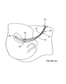
- Figure 3(a) shows the cannula 20 in its relaxed state with the inner tube 26 fully extended from the outer tube 24 and ready for insertion into the vagina 60 of a patient 62.
- the narrow inner tube 26 can fit easily into the os of the cervix 64 and from there into the uterus 66 as shown in Figure 3(c).
- Figure 3(c) also shows that the distal end portion of the outer tube 24 enters the cervical os until the sealing surface 32 of the cervical stop 28 engages with the external os of the cervix 64 and seals to it.
- the distal end 52 of the inner tube 26 bears against the fundus 68 of the uterus 66. This causes the inner tube 26 to retract into the outer tube 24 against the bias of the spring 42.
- the intra-uterine length of the cannula 20 between the distal end 52 of the inner tube 26 and the sealing surface 32 of the cervical stop 28 varies in response to insertion of the cannula 20 into the uterus 66, effecting automatic adjustment of the intra-uterine length to suit the dimensions of the uterus 66.
- the cannula 20 With the intra-uterine length of the cannula 20 closely matching the length of the uterus 66 from cervix 64 to fundus 68, the cannula 20 can be manipulated to effect reliable and easily-controllable movement of the uterus 66 during laparoscopic procedures. Yet, there is minimal risk of damage to the uterus 66 such as perforation. There is no longer a need for an assistant to manipulate the cannula 20 during a laparoscopic procedure as the curvature of the shaft 22 presents the handle 34 upwardly in a convenient location where it can be grasped easily by the physician performing laparoscopy.
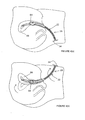
- Figures 4(a) and 4(b) show that the curvature of the shaft 22 of the first embodiment has a further advantage when a retroverted uterus is encountered as shown in Figure 4(a) .
- the cannula 20 can be oriented with the handle 34 facing downwardly so that the distal end portion of the cannula 20 also faces downwardly. This eases insertion of the distal end portion into the retroverted uterus 66.
- the cervix 64 can be used as a fulcrum about which the cannula 20 is turned through 180° until the handle 34 faces upwardly.
- the distal end portion of the cannula 20 thereby turns within the uterus 66 and lifts about the fulcrum of the cervix 64 to reorient the uterus 66 into the anteverted position shown in Figure 4(b) .
- the anteverted position In the anteverted position, exposure of the uterus 66 and the associated oviducts and ovaries (not shown) is improved.
- a cervical stop 86 mounted on the shaft 72 defines a frusto-conical sealing surface 88 that tapers distally.
- the stop 86 is shown divided into three portions 86A, 86B and 86C in distal-to-proximal order. The purpose of dividing the stop 86 in this way will be explained later.
- a movable cervical stop 86 can be applied to any embodiment of the invention.
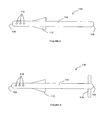
- Figures 7(a) to 7(c) show a cannula 90 in which substantially all of the length of the shaft 72 is curved but is of fixed length. Otherwise, like numerals are used for like parts in Figures 5, 6 and 7(a) to 7(c) .
- the stop 86 must move to vary the distance between the stop 86 and the distal end 92, hence to change the length of the intra-uterine distal end portion of the cannula 70, 90.
- the distal end 92 is blunt and blind.
- Movement of the cervical stop 86 along the shaft 72 can be effected either before insertion of the cannula 70, 90 into the uterus 66 or, preferably, during insertion.
- the stop 86 encounters the cervix 64 and engages with the external cervical os, which blocks further distal movement of the stop 86 as shown in Figure 7(b) ; however, the shaft 72 is still free to move distally by sliding within the stop 86.
- the length of the intra-uterine portion therefore increases from when the stop 86 engages with the cervix 64 until the distal end 92 of the shaft 72 encounters the uterine fundus 68 as shown in Figure 7(c) .
- the physician feels for increasing resistance as the distal end 92 encounters the fundus 68.
- the stop 86 slides proximally with respect to the shaft 72.
- the stop 86 may then be locked to the shaft 72 in a proximally-displaced position that defines a distal end portion length corresponding to the uterine depth.
- the cannula 70, 90 may be withdrawn and re-inserted into the uterus 66 after the stop 86 has been locked in that position.
- the cannula 70, 90 may be withdrawn from the vagina without further displacing the stop 86, whereupon the stop 86 is locked to the shaft 72 and the position of the stop 86 with respect to the shaft 72 may be read on a scale (not shown) marked on the shaft 72 to interpret the uterine depth.
- the stop 86 can be locked in a proximally-displaced position when the cannula 70, 90 is in situ within the uterus 66.
- the degree of friction between the stop 86 and the shaft 72 that resists movement of the stop 86 along the shaft 72 should be determined carefully.
- the friction that has to be overcome to move the stop 86 along the shaft 72 should not be too high; otherwise, a dangerously high force would have to be applied to the shaft 72 to move it distally into the uterus 66 once the stop 86 has engaged with the cervix 64. But nor should the friction be too low, because that friction holds the stop 86 in the desired position when the desired intra-uterine length has been achieved but before the stop 86 is locked to the shaft 72.
- the friction acting between the stop portion 86A and the shaft 72 that resists movement of the stop portion 86A along the shaft 72 can be adjusted by turning the collar 94 about the stop portion 86A to vary the extent of engagement between the threads 96, 98
- the clamping force applied to the shaft 72 increases to the extent that the stop portion 86A is eventually locked to the shaft 72.
- the stop portions 86A, 86B and 86C comprise mutually co-operable inter-engagement formations in the form of mutually complementary threads.
- the stop portions 86A and 86B each have a female thread 100 leading distally from their respective proximal ends.
- the stop portions 86B and 86C each have a male thread 102 at their respective distal ends that are complementary to the female threads 100.
- each of the stop portions 86B and 86C can be slid distally along the shaft 72 and turned about the shaft to bring its male thread 102 into engagement with the female thread 100 of the succeeding stop portion 86A or 86B.
- the invention has been described in the context of a uterine cannula having provision to inject or to aspirate fluid through a hollow interior, this is not essential.
- the invention encompasses arrangements in which the distal end portion, or indeed the shaft as a whole, is solid.
- the cervical stop is made from a plastics material but it could also be made from stainless steel or any other suitable material.
- the dilator has a shaft 104 comprising a graduated curved or straight tube or bar of fixed length or with a retractable distal end portion of any suitable diameter.
- the shaft 104 has a blind distal end 106 and either a blind or open proximal end 108. If the shaft 104 is tubular, preferably a multiplicity of holes 110 perforates the side wall of the distal part of the shaft 104.
- a cervical stop 112 could be fixed near the distal end 106 of the shaft 104 (for example about 6 cm away) or could, preferably, be slideably adjustable along the shaft as explained above. Similarly, the stop 112 could be divided like the stop 86 to suit different diameters of cervical os, the parts of the stop fitting together to form a larger whole.
- the dilators shown in Figures 8 to 11 are intended to be used after the uterus has been sounded to determine its depth.
- the cervical stop 112 can then be positioned on the shaft 104 to suit the measured uterine depth, and fixed in that position.
- the dilator is then used to dilate the cervix to the desired diameter, preferably greater than 5 mm, whereupon the dilator can be used safely as a manipulator.
- At least a distal end portion of the shaft 104 of the dilators shown in Figures 8 to 11 is semi-rigid to ease probing and dilation of the cervix while reducing the possibility of uterine perforation.
- a semi-rigid distal end portion of the dilator will tend to follow the natural path of the cervical canal by virtue of its flexible nature. This helps to avoid forming a false passage through the cervix, which is a significant cause of uterine perforation.
- a semi-rigid distal end portion could be applied to the embodiments of the invention.
- the uterine dilator 114 in Figure 8 has a straight shaft 104 carrying a conical stop 112.
- the uterine dilator 116 in Figure 9 is like that shown in Figure 8 but adds a handle 118 at the proximal end 108.
- Figure 10 shows a uterine dilator 120 having a straight shaft 104 whose opposed ends 122 and 124 are of different diameters.
- the dilator 120 may be reversed to suit different diameters of cervical os, or to start dilation with the narrower end 124 and then to continue dilation with the wider end 122.
- opposed cervical stops 112A and 112B are used, one for each end 122, 124 of the dilator 120.
- the longitudinal position of at least one of the stops 112A and 112B may be adjustable using the principle explained above.
- Figure 11 shows a dilator 126 that again has a straight shaft 104 whose opposed ends 122 and 124 are of different diameters for reversible use.
- the dilator 126 has disc-shaped cervical stops 128 disposed in parallel planes that are orthogonal to the central longitudinal axis of the shaft 104.
- the invention provides an instrument for uterine manipulation and other gynaecological procedures that can adapt, or be adapted, to suit all types, shapes and sizes of uteri and cervixes.
- the instruments of the invention drastically reduce the risk of uterine perforation or cervical trauma, while offering far better exposure than other uterine manipulators.
Landscapes
- Health & Medical Sciences (AREA)
- Life Sciences & Earth Sciences (AREA)
- Surgery (AREA)
- Engineering & Computer Science (AREA)
- Heart & Thoracic Surgery (AREA)
- Biomedical Technology (AREA)
- Veterinary Medicine (AREA)
- Animal Behavior & Ethology (AREA)
- General Health & Medical Sciences (AREA)
- Public Health (AREA)
- Anesthesiology (AREA)
- Gynecology & Obstetrics (AREA)
- Pregnancy & Childbirth (AREA)
- Reproductive Health (AREA)
- Nuclear Medicine, Radiotherapy & Molecular Imaging (AREA)
- Hematology (AREA)
- Medical Informatics (AREA)
- Molecular Biology (AREA)
- Surgical Instruments (AREA)
- Endoscopes (AREA)
Claims (10)
- Manipulateur utérin (20) comprenant une tige allongée (22) ayant une extrémité distale (52) et une butée cervicale (28) positionnée sur la tige proximalement par rapport à l'extrémité distale, dans lequel :la tige comprend des première (26) et seconde (24) parties de tige mobiles l'une par rapport à l'autre, la première partie de tige dépassant distalement au-delà de la seconde partie de tige et la butée cervicale étant fixe sur ou mobile le long de la seconde partie de tige ; etle manipulateur comprend en outre un moyen de sollicitation (42) permettant de pousser la première partie de tige distalement par rapport à la seconde partie de tige, de sorte que la longueur de la partie de la tige entre l'extrémité distale et la butée cervicale se règle automatiquement pour s'adapter à la longueur de l'utérus d'une patiente lors de l'insertion du manipulateur dans l'utérus.
- Manipulateur selon la revendication 1, dans lequel la butée est blocable sur la seconde partie de tige.
- Manipulateur selon la revendication 2, dans lequel le blocage s'effectue par des parties de pince coactionnables qui sont mobiles l'une par rapport à l'autre, une première partie de pince agissant sur une seconde partie de pince grâce audit déplacement relatif pour amener la seconde partie de pince à pincer la seconde partie de tige.
- Manipulateur selon la revendication 3, dans lequel au moins l'une des parties de pince est d'un seul tenant avec la butée.
- Manipulateur selon la revendication 3 ou la revendication 4, dans lequel la première partie de pince est disposée à l'extérieur par rapport à la seconde partie de pince lorsque les parties coopèrent pour pincer la seconde partie de pince contre la seconde partie de tige.
- Manipulateur selon l'une quelconque des revendications 3 à 5, dans lequel la seconde partie de pince est un ajustement glissant avec la seconde partie de tige.
- Manipulateur selon l'une quelconque des revendications 3 à 6, dans lequel les parties de pince sont mobiles l'une par rapport à l'autre dans une direction longitudinale par rapport à la seconde partie de tige.
- Manipulateur selon la revendication 7, dans lequel des formations de rampe des parties de pince coopèrent lors d'un mouvement longitudinal relatif des parties de pince pour amener la seconde partie de pince à pincer la seconde partie de tige.
- Manipulateur selon l'une quelconque des revendications précédentes, dans lequel la butée cervicale a une surface d'obturation de diamètre variable.
- Manipulateur selon l'une quelconque des revendications précédentes, dans lequel la tige est incurvée sur sa longueur.
Applications Claiming Priority (2)
| Application Number | Priority Date | Filing Date | Title |
|---|---|---|---|
| GBGB0607885.1A GB0607885D0 (en) | 2006-04-21 | 2006-04-21 | Improvements in or relating to uterine manipulators & dilators |
| PCT/GB2007/001401 WO2007129013A2 (fr) | 2006-04-21 | 2007-04-17 | Améliorations apportées à ou en relation avec des dispositifs pour réaliser des manipulations sur l'utérus |
Publications (2)
| Publication Number | Publication Date |
|---|---|
| EP2015829A2 EP2015829A2 (fr) | 2009-01-21 |
| EP2015829B1 true EP2015829B1 (fr) | 2015-07-22 |
Family
ID=36580991
Family Applications (1)
| Application Number | Title | Priority Date | Filing Date |
|---|---|---|---|
| EP07732443.2A Not-in-force EP2015829B1 (fr) | 2006-04-21 | 2007-04-17 | Améliorations apportées à ou en relation avec des dispositifs pour réaliser des manipulations sur l'utérus |
Country Status (4)
| Country | Link |
|---|---|
| US (1) | US8162954B2 (fr) |
| EP (1) | EP2015829B1 (fr) |
| GB (1) | GB0607885D0 (fr) |
| WO (1) | WO2007129013A2 (fr) |
Families Citing this family (20)
| Publication number | Priority date | Publication date | Assignee | Title |
|---|---|---|---|---|
| US8608738B2 (en) | 2010-12-06 | 2013-12-17 | Soulor Surgical, Inc. | Apparatus for treating a portion of a reproductive system and related methods of use |
| US9987042B2 (en) * | 2011-04-07 | 2018-06-05 | Jai Singh | General uterine manipulator and system |
| US20130023896A1 (en) * | 2011-07-20 | 2013-01-24 | Quimby Jennifer C | Surgical manipulation and occlusion device |
| SI24011B (sl) | 2012-03-14 | 2020-11-30 | Rok TomaĹľeviÄŤ | MEDICINSKI INšTRUMENT ZA NADZOROVANO VODENJE MATERNICE |
| US20130269705A1 (en) | 2012-04-16 | 2013-10-17 | Thomas C. Kochem | Variable stiffness flexure |
| US9089365B2 (en) | 2012-04-26 | 2015-07-28 | Imds Llc | Tissue fixation device |
| US20140200591A1 (en) * | 2013-01-11 | 2014-07-17 | Hologic, Inc. | Cervical sealing apparatus |
| US9333111B2 (en) | 2013-02-04 | 2016-05-10 | Hologic, Inc. | Fundus bumper mechanical reference for easier mechanism deployment |
| WO2014121333A1 (fr) * | 2013-02-06 | 2014-08-14 | Sillender Mark | Cathéter et méthode de transfert d'embryon |
| BR112015022686B1 (pt) * | 2013-03-12 | 2022-10-04 | Puja Ahluwalia | Manipulador uterino |
| US9895192B2 (en) | 2013-03-13 | 2018-02-20 | Hologic, Inc. | Intrauterine treatment device with articulating array |
| CA2962609A1 (fr) | 2014-10-15 | 2016-04-21 | Covidien Lp | Endoscope comportant une section de travail multidiametre |
| WO2017004034A1 (fr) * | 2015-06-29 | 2017-01-05 | Covidien Lp | Dispositif de sonde utérine et procédés d'utilisation associés |
| US10799269B2 (en) * | 2017-09-18 | 2020-10-13 | Carlos Navarro Alvarez | Transfer assembly |
| ES2906283T3 (es) * | 2017-09-27 | 2022-04-18 | Bayer Oy | Un insertador para un sistema intrauterino |
| CN108619610B (zh) * | 2018-05-21 | 2024-11-12 | 浙江省人民医院 | 宫腔输卵管造影管 |
| WO2020014137A1 (fr) * | 2018-07-09 | 2020-01-16 | Previvo Genetics, Inc. | Dispositifs, systèmes et procédés de lavage utérin |
| CN110833444A (zh) * | 2018-08-16 | 2020-02-25 | 瑟基(上海)医疗器械有限公司 | 一次性可调节举宫器 |
| WO2020182535A1 (fr) * | 2019-03-08 | 2020-09-17 | Bayer Oy | Tube de sonde utérine ayant un applicateur d'anesthésique |
| CN113476120B (zh) * | 2021-07-12 | 2022-10-25 | 颜达立 | 一种妇产科用于治疗宫颈内道的清理仪器 |
Citations (1)
| Publication number | Priority date | Publication date | Assignee | Title |
|---|---|---|---|---|
| US4489732A (en) * | 1982-09-20 | 1984-12-25 | Hasson Harrith M | Gynecological instrument |
Family Cites Families (13)
| Publication number | Priority date | Publication date | Assignee | Title |
|---|---|---|---|---|
| US3796211A (en) | 1972-08-07 | 1974-03-12 | Medics Res & Dev Inc | Biopsy sampling method and device for the female genital tract |
| US4016867A (en) * | 1976-04-27 | 1977-04-12 | The United States Of America As Represented By The Secretary Of The Department Of Health, Education And Welfare | Uterine caliper and depth gauge |
| US4089337A (en) | 1976-12-01 | 1978-05-16 | James H. Harris | Uterine catheter and manipulator with inflatable seal |
| US4997419A (en) * | 1989-06-01 | 1991-03-05 | Edward Weck Incoporated | Laparoscopy cannula |
| US5147316A (en) * | 1990-11-19 | 1992-09-15 | Castillenti Thomas A | Laparoscopic trocar with self-locking port sleeve |
| US5368598A (en) | 1991-04-19 | 1994-11-29 | Hasson; Harrith M. | Method of manipulating an uterus using a bendable manipulator |
| US5540658A (en) | 1994-06-27 | 1996-07-30 | Innerdyne, Inc. | Transcervical uterine access and sealing device |
| US5769880A (en) * | 1996-04-12 | 1998-06-23 | Novacept | Moisture transport system for contact electrocoagulation |
| US6706026B1 (en) * | 1996-08-09 | 2004-03-16 | Cook Urological Incorporated | Instillation uterine catheter |
| AU773391B2 (en) | 2000-05-22 | 2004-05-27 | Jiwan Steven Dr Singh | Uterine cannula and pelvic suport for gynaecological laparoscopy |
| US20050085827A1 (en) * | 2003-10-15 | 2005-04-21 | G. Anselmo N. | Uterine manipulating device |
| DE202004019868U1 (de) | 2004-12-16 | 2005-02-24 | Karl Storz Gmbh & Co. Kg | Medizinisches Instrument, insbesondere Uterusmanipulator |
| GB0509565D0 (en) | 2005-05-11 | 2005-06-15 | Univ Nottingham | A novel uterine cannula for use in gynaecological procedures |
-
2006
- 2006-04-21 GB GBGB0607885.1A patent/GB0607885D0/en not_active Ceased
-
2007
- 2007-04-17 EP EP07732443.2A patent/EP2015829B1/fr not_active Not-in-force
- 2007-04-17 US US12/297,749 patent/US8162954B2/en active Active
- 2007-04-17 WO PCT/GB2007/001401 patent/WO2007129013A2/fr not_active Ceased
Patent Citations (1)
| Publication number | Priority date | Publication date | Assignee | Title |
|---|---|---|---|---|
| US4489732A (en) * | 1982-09-20 | 1984-12-25 | Hasson Harrith M | Gynecological instrument |
Also Published As
| Publication number | Publication date |
|---|---|
| EP2015829A2 (fr) | 2009-01-21 |
| US20090137970A1 (en) | 2009-05-28 |
| WO2007129013A3 (fr) | 2008-04-17 |
| US8162954B2 (en) | 2012-04-24 |
| WO2007129013A2 (fr) | 2007-11-15 |
| GB0607885D0 (en) | 2006-05-31 |
Similar Documents
| Publication | Publication Date | Title |
|---|---|---|
| US8162954B2 (en) | Uterine manipulators | |
| US8740916B2 (en) | Uterine manipulator assemblies and related components and methods | |
| US6293952B1 (en) | Medical instrument system for piercing through tissue | |
| JP5028258B2 (ja) | 膀胱切開用カテーテル捕捉器具及びその使用方法 | |
| EP2231040B1 (fr) | Manipulateur uterin a usage unique jetable | |
| US6156006A (en) | Medical instrument system for piercing through tissue | |
| US9114228B2 (en) | Dilator apparatus | |
| US20100145224A1 (en) | Canal dilation device | |
| CA3023410C (fr) | Manipulateur uterin | |
| US20030158521A1 (en) | Trocar placement guide needle | |
| US20220096123A1 (en) | Tools and methods for vaginal access | |
| JPH08500745A (ja) | 膣頚部レトラクタ・エレベイタ | |
| JP2004535863A (ja) | 尿道プロファイル装置ならびにそのための方法。 | |
| JPH0397469A (ja) | 子宮アクセス装置 | |
| EP1420706A2 (fr) | Dispositiv de manipulation de l'uterus pour la colpotomie et l'hysterectomie | |
| US20090048609A1 (en) | Uterine cannula | |
| US20070232988A1 (en) | Abdominal Insufflator and Principal Trocar-Cannula Screw Device | |
| WO2007118070A2 (fr) | Insufflateur abdominal et dispositif principal a vis a trocart et canule | |
| CN112121287A (zh) | 一种脑脊液腹腔分流术可调分流阀定位装置 |
Legal Events
| Date | Code | Title | Description |
|---|---|---|---|
| PUAI | Public reference made under article 153(3) epc to a published international application that has entered the european phase |
Free format text: ORIGINAL CODE: 0009012 |
|
| 17P | Request for examination filed |
Effective date: 20081121 |
|
| AK | Designated contracting states |
Kind code of ref document: A2 Designated state(s): AT BE BG CH CY CZ DE DK EE ES FI FR GB GR HU IE IS IT LI LT LU LV MC MT NL PL PT RO SE SI SK TR |
|
| AX | Request for extension of the european patent |
Extension state: AL BA HR MK RS |
|
| DAX | Request for extension of the european patent (deleted) | ||
| 17Q | First examination report despatched |
Effective date: 20140401 |
|
| GRAP | Despatch of communication of intention to grant a patent |
Free format text: ORIGINAL CODE: EPIDOSNIGR1 |
|
| INTG | Intention to grant announced |
Effective date: 20150224 |
|
| GRAS | Grant fee paid |
Free format text: ORIGINAL CODE: EPIDOSNIGR3 |
|
| GRAA | (expected) grant |
Free format text: ORIGINAL CODE: 0009210 |
|
| AK | Designated contracting states |
Kind code of ref document: B1 Designated state(s): AT BE BG CH CY CZ DE DK EE ES FI FR GB GR HU IE IS IT LI LT LU LV MC MT NL PL PT RO SE SI SK TR |
|
| REG | Reference to a national code |
Ref country code: GB Ref legal event code: FG4D |
|
| REG | Reference to a national code |
Ref country code: CH Ref legal event code: EP |
|
| REG | Reference to a national code |
Ref country code: IE Ref legal event code: FG4D |
|
| REG | Reference to a national code |
Ref country code: AT Ref legal event code: REF Ref document number: 737542 Country of ref document: AT Kind code of ref document: T Effective date: 20150815 |
|
| REG | Reference to a national code |
Ref country code: DE Ref legal event code: R096 Ref document number: 602007042242 Country of ref document: DE |
|
| REG | Reference to a national code |
Ref country code: AT Ref legal event code: MK05 Ref document number: 737542 Country of ref document: AT Kind code of ref document: T Effective date: 20150722 |
|
| REG | Reference to a national code |
Ref country code: LT Ref legal event code: MG4D |
|
| REG | Reference to a national code |
Ref country code: NL Ref legal event code: MP Effective date: 20150722 |
|
| PG25 | Lapsed in a contracting state [announced via postgrant information from national office to epo] |
Ref country code: LT Free format text: LAPSE BECAUSE OF FAILURE TO SUBMIT A TRANSLATION OF THE DESCRIPTION OR TO PAY THE FEE WITHIN THE PRESCRIBED TIME-LIMIT Effective date: 20150722 Ref country code: FI Free format text: LAPSE BECAUSE OF FAILURE TO SUBMIT A TRANSLATION OF THE DESCRIPTION OR TO PAY THE FEE WITHIN THE PRESCRIBED TIME-LIMIT Effective date: 20150722 Ref country code: LV Free format text: LAPSE BECAUSE OF FAILURE TO SUBMIT A TRANSLATION OF THE DESCRIPTION OR TO PAY THE FEE WITHIN THE PRESCRIBED TIME-LIMIT Effective date: 20150722 Ref country code: GR Free format text: LAPSE BECAUSE OF FAILURE TO SUBMIT A TRANSLATION OF THE DESCRIPTION OR TO PAY THE FEE WITHIN THE PRESCRIBED TIME-LIMIT Effective date: 20151023 |
|
| PG25 | Lapsed in a contracting state [announced via postgrant information from national office to epo] |
Ref country code: PT Free format text: LAPSE BECAUSE OF FAILURE TO SUBMIT A TRANSLATION OF THE DESCRIPTION OR TO PAY THE FEE WITHIN THE PRESCRIBED TIME-LIMIT Effective date: 20151123 Ref country code: SE Free format text: LAPSE BECAUSE OF FAILURE TO SUBMIT A TRANSLATION OF THE DESCRIPTION OR TO PAY THE FEE WITHIN THE PRESCRIBED TIME-LIMIT Effective date: 20150722 Ref country code: ES Free format text: LAPSE BECAUSE OF FAILURE TO SUBMIT A TRANSLATION OF THE DESCRIPTION OR TO PAY THE FEE WITHIN THE PRESCRIBED TIME-LIMIT Effective date: 20150722 Ref country code: PL Free format text: LAPSE BECAUSE OF FAILURE TO SUBMIT A TRANSLATION OF THE DESCRIPTION OR TO PAY THE FEE WITHIN THE PRESCRIBED TIME-LIMIT Effective date: 20150722 Ref country code: IS Free format text: LAPSE BECAUSE OF FAILURE TO SUBMIT A TRANSLATION OF THE DESCRIPTION OR TO PAY THE FEE WITHIN THE PRESCRIBED TIME-LIMIT Effective date: 20151122 Ref country code: AT Free format text: LAPSE BECAUSE OF FAILURE TO SUBMIT A TRANSLATION OF THE DESCRIPTION OR TO PAY THE FEE WITHIN THE PRESCRIBED TIME-LIMIT Effective date: 20150722 |
|
| REG | Reference to a national code |
Ref country code: DE Ref legal event code: R097 Ref document number: 602007042242 Country of ref document: DE |
|
| PG25 | Lapsed in a contracting state [announced via postgrant information from national office to epo] |
Ref country code: CZ Free format text: LAPSE BECAUSE OF FAILURE TO SUBMIT A TRANSLATION OF THE DESCRIPTION OR TO PAY THE FEE WITHIN THE PRESCRIBED TIME-LIMIT Effective date: 20150722 Ref country code: IT Free format text: LAPSE BECAUSE OF FAILURE TO SUBMIT A TRANSLATION OF THE DESCRIPTION OR TO PAY THE FEE WITHIN THE PRESCRIBED TIME-LIMIT Effective date: 20150722 Ref country code: EE Free format text: LAPSE BECAUSE OF FAILURE TO SUBMIT A TRANSLATION OF THE DESCRIPTION OR TO PAY THE FEE WITHIN THE PRESCRIBED TIME-LIMIT Effective date: 20150722 Ref country code: SK Free format text: LAPSE BECAUSE OF FAILURE TO SUBMIT A TRANSLATION OF THE DESCRIPTION OR TO PAY THE FEE WITHIN THE PRESCRIBED TIME-LIMIT Effective date: 20150722 Ref country code: DK Free format text: LAPSE BECAUSE OF FAILURE TO SUBMIT A TRANSLATION OF THE DESCRIPTION OR TO PAY THE FEE WITHIN THE PRESCRIBED TIME-LIMIT Effective date: 20150722 |
|
| PLBE | No opposition filed within time limit |
Free format text: ORIGINAL CODE: 0009261 |
|
| STAA | Information on the status of an ep patent application or granted ep patent |
Free format text: STATUS: NO OPPOSITION FILED WITHIN TIME LIMIT |
|
| PG25 | Lapsed in a contracting state [announced via postgrant information from national office to epo] |
Ref country code: RO Free format text: LAPSE BECAUSE OF FAILURE TO SUBMIT A TRANSLATION OF THE DESCRIPTION OR TO PAY THE FEE WITHIN THE PRESCRIBED TIME-LIMIT Effective date: 20150722 |
|
| 26N | No opposition filed |
Effective date: 20160425 |
|
| PG25 | Lapsed in a contracting state [announced via postgrant information from national office to epo] |
Ref country code: BE Free format text: LAPSE BECAUSE OF NON-PAYMENT OF DUE FEES Effective date: 20160430 Ref country code: SI Free format text: LAPSE BECAUSE OF FAILURE TO SUBMIT A TRANSLATION OF THE DESCRIPTION OR TO PAY THE FEE WITHIN THE PRESCRIBED TIME-LIMIT Effective date: 20150722 |
|
| REG | Reference to a national code |
Ref country code: DE Ref legal event code: R119 Ref document number: 602007042242 Country of ref document: DE |
|
| REG | Reference to a national code |
Ref country code: CH Ref legal event code: PL |
|
| PG25 | Lapsed in a contracting state [announced via postgrant information from national office to epo] |
Ref country code: BE Free format text: LAPSE BECAUSE OF FAILURE TO SUBMIT A TRANSLATION OF THE DESCRIPTION OR TO PAY THE FEE WITHIN THE PRESCRIBED TIME-LIMIT Effective date: 20150722 Ref country code: LU Free format text: LAPSE BECAUSE OF FAILURE TO SUBMIT A TRANSLATION OF THE DESCRIPTION OR TO PAY THE FEE WITHIN THE PRESCRIBED TIME-LIMIT Effective date: 20160417 |
|
| REG | Reference to a national code |
Ref country code: IE Ref legal event code: MM4A |
|
| REG | Reference to a national code |
Ref country code: FR Ref legal event code: ST Effective date: 20161230 |
|
| PG25 | Lapsed in a contracting state [announced via postgrant information from national office to epo] |
Ref country code: DE Free format text: LAPSE BECAUSE OF NON-PAYMENT OF DUE FEES Effective date: 20161101 Ref country code: LI Free format text: LAPSE BECAUSE OF NON-PAYMENT OF DUE FEES Effective date: 20160430 Ref country code: CH Free format text: LAPSE BECAUSE OF NON-PAYMENT OF DUE FEES Effective date: 20160430 Ref country code: FR Free format text: LAPSE BECAUSE OF NON-PAYMENT OF DUE FEES Effective date: 20160502 |
|
| PG25 | Lapsed in a contracting state [announced via postgrant information from national office to epo] |
Ref country code: IE Free format text: LAPSE BECAUSE OF NON-PAYMENT OF DUE FEES Effective date: 20160417 |
|
| PG25 | Lapsed in a contracting state [announced via postgrant information from national office to epo] |
Ref country code: NL Free format text: LAPSE BECAUSE OF FAILURE TO SUBMIT A TRANSLATION OF THE DESCRIPTION OR TO PAY THE FEE WITHIN THE PRESCRIBED TIME-LIMIT Effective date: 20150722 |
|
| PG25 | Lapsed in a contracting state [announced via postgrant information from national office to epo] |
Ref country code: CY Free format text: LAPSE BECAUSE OF FAILURE TO SUBMIT A TRANSLATION OF THE DESCRIPTION OR TO PAY THE FEE WITHIN THE PRESCRIBED TIME-LIMIT Effective date: 20150722 Ref country code: HU Free format text: LAPSE BECAUSE OF FAILURE TO SUBMIT A TRANSLATION OF THE DESCRIPTION OR TO PAY THE FEE WITHIN THE PRESCRIBED TIME-LIMIT; INVALID AB INITIO Effective date: 20070417 |
|
| PG25 | Lapsed in a contracting state [announced via postgrant information from national office to epo] |
Ref country code: TR Free format text: LAPSE BECAUSE OF FAILURE TO SUBMIT A TRANSLATION OF THE DESCRIPTION OR TO PAY THE FEE WITHIN THE PRESCRIBED TIME-LIMIT Effective date: 20150722 Ref country code: MC Free format text: LAPSE BECAUSE OF FAILURE TO SUBMIT A TRANSLATION OF THE DESCRIPTION OR TO PAY THE FEE WITHIN THE PRESCRIBED TIME-LIMIT Effective date: 20150722 Ref country code: MT Free format text: LAPSE BECAUSE OF NON-PAYMENT OF DUE FEES Effective date: 20160430 |
|
| PG25 | Lapsed in a contracting state [announced via postgrant information from national office to epo] |
Ref country code: BG Free format text: LAPSE BECAUSE OF FAILURE TO SUBMIT A TRANSLATION OF THE DESCRIPTION OR TO PAY THE FEE WITHIN THE PRESCRIBED TIME-LIMIT Effective date: 20150722 |
|
| PGFP | Annual fee paid to national office [announced via postgrant information from national office to epo] |
Ref country code: GB Payment date: 20210305 Year of fee payment: 15 |
|
| GBPC | Gb: european patent ceased through non-payment of renewal fee |
Effective date: 20220417 |
|
| PG25 | Lapsed in a contracting state [announced via postgrant information from national office to epo] |
Ref country code: GB Free format text: LAPSE BECAUSE OF NON-PAYMENT OF DUE FEES Effective date: 20220417 |