EP2017061A1 - Spritzgießmaschine mit Mitteln zum Feststellens des Schliessens des Sperrrings - Google Patents
Spritzgießmaschine mit Mitteln zum Feststellens des Schliessens des Sperrrings Download PDFInfo
- Publication number
- EP2017061A1 EP2017061A1 EP07122817A EP07122817A EP2017061A1 EP 2017061 A1 EP2017061 A1 EP 2017061A1 EP 07122817 A EP07122817 A EP 07122817A EP 07122817 A EP07122817 A EP 07122817A EP 2017061 A1 EP2017061 A1 EP 2017061A1
- Authority
- EP
- European Patent Office
- Prior art keywords
- screw
- check ring
- torque
- closed
- reverse rotation
- Prior art date
- Legal status (The legal status is an assumption and is not a legal conclusion. Google has not performed a legal analysis and makes no representation as to the accuracy of the status listed.)
- Granted
Links
- 238000001746 injection moulding Methods 0.000 title claims description 42
- 238000006798 ring closing metathesis reaction Methods 0.000 title claims description 33
- 230000033001 locomotion Effects 0.000 claims description 23
- 238000002347 injection Methods 0.000 description 48
- 239000007924 injection Substances 0.000 description 48
- 239000011347 resin Substances 0.000 description 19
- 229920005989 resin Polymers 0.000 description 19
- 238000000034 method Methods 0.000 description 8
- 238000000465 moulding Methods 0.000 description 5
- 230000007423 decrease Effects 0.000 description 4
- 238000009825 accumulation Methods 0.000 description 2
- 230000005540 biological transmission Effects 0.000 description 2
- 238000013500 data storage Methods 0.000 description 2
- 238000010586 diagram Methods 0.000 description 2
- 101100290429 Mus musculus Mcm3 gene Proteins 0.000 description 1
- 230000004913 activation Effects 0.000 description 1
- 238000006243 chemical reaction Methods 0.000 description 1
- 230000000694 effects Effects 0.000 description 1
- 230000006870 function Effects 0.000 description 1
- 239000004973 liquid crystal related substance Substances 0.000 description 1
- 239000008188 pellet Substances 0.000 description 1
- 238000005070 sampling Methods 0.000 description 1
Images




Classifications
-
- B—PERFORMING OPERATIONS; TRANSPORTING
- B29—WORKING OF PLASTICS; WORKING OF SUBSTANCES IN A PLASTIC STATE IN GENERAL
- B29C—SHAPING OR JOINING OF PLASTICS; SHAPING OF MATERIAL IN A PLASTIC STATE, NOT OTHERWISE PROVIDED FOR; AFTER-TREATMENT OF THE SHAPED PRODUCTS, e.g. REPAIRING
- B29C45/00—Injection moulding, i.e. forcing the required volume of moulding material through a nozzle into a closed mould; Apparatus therefor
- B29C45/17—Component parts, details or accessories; Auxiliary operations
- B29C45/46—Means for plasticising or homogenising the moulding material or forcing it into the mould
- B29C45/47—Means for plasticising or homogenising the moulding material or forcing it into the mould using screws
- B29C45/50—Axially movable screw
- B29C45/52—Non-return devices
-
- B—PERFORMING OPERATIONS; TRANSPORTING
- B29—WORKING OF PLASTICS; WORKING OF SUBSTANCES IN A PLASTIC STATE IN GENERAL
- B29C—SHAPING OR JOINING OF PLASTICS; SHAPING OF MATERIAL IN A PLASTIC STATE, NOT OTHERWISE PROVIDED FOR; AFTER-TREATMENT OF THE SHAPED PRODUCTS, e.g. REPAIRING
- B29C45/00—Injection moulding, i.e. forcing the required volume of moulding material through a nozzle into a closed mould; Apparatus therefor
- B29C45/17—Component parts, details or accessories; Auxiliary operations
- B29C45/76—Measuring, controlling or regulating
-
- B—PERFORMING OPERATIONS; TRANSPORTING
- B29—WORKING OF PLASTICS; WORKING OF SUBSTANCES IN A PLASTIC STATE IN GENERAL
- B29C—SHAPING OR JOINING OF PLASTICS; SHAPING OF MATERIAL IN A PLASTIC STATE, NOT OTHERWISE PROVIDED FOR; AFTER-TREATMENT OF THE SHAPED PRODUCTS, e.g. REPAIRING
- B29C2945/00—Indexing scheme relating to injection moulding, i.e. forcing the required volume of moulding material through a nozzle into a closed mould
- B29C2945/76—Measuring, controlling or regulating
- B29C2945/76003—Measured parameter
- B29C2945/7602—Torque
-
- B—PERFORMING OPERATIONS; TRANSPORTING
- B29—WORKING OF PLASTICS; WORKING OF SUBSTANCES IN A PLASTIC STATE IN GENERAL
- B29C—SHAPING OR JOINING OF PLASTICS; SHAPING OF MATERIAL IN A PLASTIC STATE, NOT OTHERWISE PROVIDED FOR; AFTER-TREATMENT OF THE SHAPED PRODUCTS, e.g. REPAIRING
- B29C2945/00—Indexing scheme relating to injection moulding, i.e. forcing the required volume of moulding material through a nozzle into a closed mould
- B29C2945/76—Measuring, controlling or regulating
- B29C2945/76177—Location of measurement
- B29C2945/7618—Injection unit
- B29C2945/76187—Injection unit screw
-
- B—PERFORMING OPERATIONS; TRANSPORTING
- B29—WORKING OF PLASTICS; WORKING OF SUBSTANCES IN A PLASTIC STATE IN GENERAL
- B29C—SHAPING OR JOINING OF PLASTICS; SHAPING OF MATERIAL IN A PLASTIC STATE, NOT OTHERWISE PROVIDED FOR; AFTER-TREATMENT OF THE SHAPED PRODUCTS, e.g. REPAIRING
- B29C2945/00—Indexing scheme relating to injection moulding, i.e. forcing the required volume of moulding material through a nozzle into a closed mould
- B29C2945/76—Measuring, controlling or regulating
- B29C2945/76344—Phase or stage of measurement
- B29C2945/76367—Metering
-
- B—PERFORMING OPERATIONS; TRANSPORTING
- B29—WORKING OF PLASTICS; WORKING OF SUBSTANCES IN A PLASTIC STATE IN GENERAL
- B29C—SHAPING OR JOINING OF PLASTICS; SHAPING OF MATERIAL IN A PLASTIC STATE, NOT OTHERWISE PROVIDED FOR; AFTER-TREATMENT OF THE SHAPED PRODUCTS, e.g. REPAIRING
- B29C2945/00—Indexing scheme relating to injection moulding, i.e. forcing the required volume of moulding material through a nozzle into a closed mould
- B29C2945/76—Measuring, controlling or regulating
- B29C2945/76494—Controlled parameter
- B29C2945/76545—Flow rate
Definitions
- the present invention relates to an injection molding machine, and more particularly to an injection molding machine that determines whether a check ring is closed or not during forward movement of a screw and rotates the screw in reverse by an amount necessary to close the check ring.
- the check ring in an injection molding machine is closed by rotating the screw in reverse (or in the direction reverse to the direction of the screw during metering process) at the start of injection.
- the amount of reverse rotation of the screw is calculated and set according to the spacing between the check ring and check seat when the check ring is open.
- the screw is rotated in reverse in synchronization with the injection speed during injection process.
- the check ring is closed by rotating the screw in reverse while moving it in positive direction during the period between metering and injection.
- the amount by which the screw must be rotated in reverse to close the check ring varies with the resin viscosity, injection speed, and other conditions. Therefore, if the amount of reverse rotation at injection is set as described in the above conventional art, the amount may be not enough to close the check ring completely, or the amount may be excessive, depending on the resin and molding conditions.
- the object of the present invention is to provide an injection molding machine that performs control so as to rotate the screw in reverse by the optimal amount for reliably closing the check ring of the screw.
- the injection molding machine includes a screw equipped with a check ring, torque detecting means for detecting torque acting on the screw during forward movement of the screw, check ring closure state determining means for determining whether the check ring is closed or not on the basis of the torque detected by the torque detecting means, and screw reverse rotation control means for controlling reverse rotation of the screw on the basis of the determination by the check ring closure state determining means.
- the check ring closure state determining means may compare torque during forward movement of the screw with a first reference value, and determine that the check ring is not closed when the torque is greater than the first reference value or that the check ring is closed when the torque is less than or equal to the first reference value.
- the check ring closure state determining means may determine that the check ring is closed at a point of time when the torque reaches a peak and that the check ring remains closed after a point of time when the peak appears.
- the check ring closure state determining means may compare an integrated value of the torque from the start of forward movement of the screw to the current time with a second reference value, and determine that the check ring is not closed when the integrated value of the torque is greater than the second reference value or that the check ring is closed when the integrated value of the torque is less than or equal to the second reference value.
- the screw reverse rotation control means may rotate the screw in reverse when the check ring is determined not to be closed or may stop the reverse rotation of the screw when the check ring is determined to be closed.
- the screw reverse rotation control means may rotate the screw in reverse from when the screw starts moving forward until a first predetermined time elapses, or until the screw moves forward a first predetermined distance from the screw position at a point of time when the screw starts moving forward, regardless of the determination by the check ring closure state determining means.
- the screw reverse rotation control means may stop the reverse rotation of the screw after a second predetermined time has elapsed since the check ring closure state determining means determined that the check ring was closed, or after the screw has moved forward a second predetermined distance from the screw position at a point of time when the check ring was determined to be closed.
- the injection molding machine may include display means for displaying an amount of reverse rotation of the screw from when the screw starts rotating in reverse until the check ring closure state determining means determines that the check ring is closed.
- the forward movement of the screw may be forward screw movement in the injection process or forward screw movement in the interval from the completion of metering to the start of injection.
- the injection molding machine according to the present invention can reliably close the check ring even if the resin viscosity and other conditions vary. It is also possible to minimize the increase in metering time and accumulation of resin due to reverse rotation of the screw. In addition, if the amount of reverse rotation of the screw necessary to close the check ring is displayed on the screen, the operator can use the displayed value as a guide for setting an amount of reverse rotation of the screw.
- FIG. 1 is a block diagram showing the main sections of an injection molding machine in an embodiment of the present invention.
- An injection cylinder 2 in which a screw 12 is inserted, has a nozzle 1 at its front end.
- the injection cylinder 2 has a hopper 3 near its rear end, through which resin pellets are supplied to the injection cylinder 2.
- the screw 12 is rotated when driven by a screw rotating servo motor 9 through a transmission mechanism 11.
- the screw 12 is also axially driven to control injection and back pressure by an injection servo motor 5 through a transmission mechanism 4 and a conversion mechanism 7 such as a ball screw and nut that converts rotational motion into rectilinear motion.
- the injection servo motor 5 and screw rotating servo motor 9 are equipped with respective position/speed detecting devices 6, 10 for detecting their rotational position and speed.
- the position/speed detecting devices 6, 10 are used to detect the rotational position and speed of the screw 12 as well as the longitudinal position and speed (injection speed) of the screw 12 in the axial direction.
- a control unit 29 for controlling the injection molding machine has a CNC CPU 21, which is a microprocessor for numerical control, a PMC CPU 20, which is a microprocessor for a programmable machine controller, and a servo CPU 16, which is a microprocessor for servo control. These microprocessors can interact by selective mutual input and output of information through a bus 19.
- the servo CPU 16 is connected to a ROM 18 in which a dedicated servo control program for position, speed, and electric current loop processing is stored, and a RAM 17 for temporarily storing arithmetic data.
- the servo CPU 16 is also connected through an analog-to-digital (A/D) converter 15 to a pressure sensor 8 disposed on the main body of the injection molding machine for detecting various types of pressure such as injection pressure.
- the pressure sensor 8 may be a load converter (load cell), for example.
- the servo CPU 16 is connected to a servo amplifier 14 for driving the injection servo motor 5, which is connected to an injection axis, and a servo amplifier 13 for driving the screw rotating servo motor 9, which is connected to a screw rotating axis; the amplifiers drive their respective motors according to commands from the servo CPU 16.
- the outputs of the position/speed detecting devices 6, 10 with which the servo motors 5, 9 are equipped are fed back to the servo CPU 16.
- the rotational position of the servo motors 5, 9 is calculated by the servo CPU 16 according to positional feedback signals from the position/speed detecting devices 6, 10, and updated and stored in respective current position storage registers.
- the axis configuration shown in FIG. 1 includes only the servo motors 5, 9 for driving the injection and screw rotating axes, the position/speed detecting devices 6, 10 for detecting the rotational position and speed of the servo motors 5, 9, and the servo amplifiers 13, 14.
- Other axes such as a mold clamping axis for clamping a mold and an ejector axis for removing a molded article from the mold, are provided in a configuration (including servo motors, amplifiers, and position/speed detecting devices) similar to the configuration shown, so they are omitted in FIG. 1 .
- the PMC CPU 20 is connected to a ROM 28 where programs such as a sequence program for controlling the operation sequence of the injection molding machine are stored, and a RAM 27 for temporarily storing arithmetic data.
- the CNC CPU 21 is connected to a ROM 26 where programs such as an automatic operation program for controlling the injection molding machine as a whole and a processing program related to the present invention for determining when to complete suck-back are stored, and a RAM 25 for temporarily storing arithmetic data.
- a molding data storage RAM 22 incorporating nonvolatile memory elements stores data related to injection molding, such as molding conditions, various settings, parameters, and macro variables.
- a manual data input device 24 with a display is connected through a display circuit 23 to the bus 19, enabling operations such as selection of a graph display screen or function menu and input of various types of data.
- a CRT, liquid crystal, or any other type of display may be selected as appropriate.
- the display circuit 23 has a check ring closure indicator, which will be described later, and is used to display the amount by which the screw is rotated in reverse in the interval from when the screw starts rotating in reverse until the check ring is determined to be closed.
- the PMC CPU 20 controls the operation sequence of the injection molding machine as a whole; the CNC CPU 21 distributes motion commands to the servo motors for respective axes according to the operation programs in the ROM 26 and molding conditions and other data stored in the molding data storage RAM 22; and the servo CPU 16 performs conventional servo control such as position loop control, speed loop control, and current loop control according to the motion commands distributed to the axes and the position, speed, and other feedback signals detected by the position/speed detecting devices 6, 10.
- control unit 29 for controlling this injection molding machine incorporates means for controlling reverse rotation of the screw according to the present invention.
- the control unit 29 shown in FIG. 1 differs from the control unit in conventional electrically-powered injection molding machines in that the ROM 26 contains a processing program for detecting torque acting on the flight section of a screw equipped with a check ring and controlling reverse rotation of the screw on the basis of the detected torque.
- the injection molding machine controls reverse rotation of the screw equipped with the check ring by using the CNC CPU 21 to execute the processing program.
- FIG. 2 illustrates how the force of resin backflow acts on the screw 12 during forward movement of the screw in, for example, the injection process.
- the check ring 30 is not closed completely, resin flows rotating in reverse, producing a force F pressing a flight 32 of the screw 12 forward.
- the flight 32 is formed so as to extend in an oblique direction with respect to the axial direction of the screw, so the force F is divided into a component Fx in the axial direction of the screw and a component F ⁇ in the direction of rotation about the screw axis.
- the component F ⁇ in the direction of rotation acts so as to rotate the screw in reverse.
- the component F ⁇ is measured, to detect resin backflow and determine the state of the check ring.
- FIG. 3 illustrates how an observer is used as the torque detecting means.
- a positional deviation counter 33 obtains the positional difference between a position command MCMD sent from the CNC CPU 21 to the screw rotating servo motor 9 and the actual rotational position of the screw rotating servo motor 9 detected by the position/speed detecting device 10.
- a position control section 34 obtains a speed command by multiplying the positional difference by a position loop gain.
- a speed deviation is obtained by subtracting the actual speed of the screw rotating servo motor 9 detected by the position/speed detecting device 10 from the speed command.
- a speed control section 35 obtains a current command u by performing speed loop processing, and a current control section 36 performs current loop processing for the obtained current command u, to drive the screw rotating servo motor 9.
- An observer 37 receives the torque command (current command) u obtained by speed loop processing and the actual speed fed back from the position/speed detecting device 10 of the screw rotating servo motor 9, and estimates the screw torque (load torque).
- the screw torque may be obtained by detecting the current for driving the screw rotating servo motor 9, instead of by using the above observer, or in an injection molding machine with a hydraulic motor, the screw torque may be obtained by detecting the hydraulic pressure of the hydraulic motor. Furthermore, a strain sensor may be mounted on the screw to obtain the screw torque.
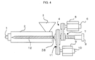
- FIG. 4 shows a strain sensor 38 attached to the surface of the screw 12 in an area outside the injection cylinder 2 to detect screw torque.
- the screw produces a strain due to torque, so the screw torque may be obtained by detecting the strain. If screw rotation is stopped by braking means, the screw torque may be detected by the strain sensor mounted on the screw.
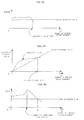
- FIGS. 5A, 5B, and 5C illustrate respective exemplary criteria used by the check ring closure state determining means to determine whether the check ring is closed or not.
- the preset torque value is used as a first reference value: the check ring is determined not to be closed when the torque is greater than the first reference value, and to be closed when the torque is less than or equal to the first reference value.
- the horizontal axis represents time from a point of time when injection starts or amount of forward movement of the screw from a point of time when injection starts, and the vertical axis represents screw torque.
- the screw reverse rotation control means controls reverse rotation of the screw on the basis of the determination by the check ring closure state determining means. More specifically, the screw reverse rotation control means rotates the screw in reverse when the check ring closure state determining means determines that the check ring is not closed, and stops the reverse rotation of the screw when the check ring closure state determining means determines that the check ring is closed.
- the screw may be rotated in reverse from a point of time when the screw starts moving forward until a first predetermined time elapses, or from a point of time when the screw starts moving forward until the screw has moved forward a first predetermined distance, regardless of the determination by the check ring closure state determining means.
- the reverse rotation of the screw may be stopped at a point of time when a second predetermined time has elapsed since the check ring was determined to be closed, or at a point of time when the screw has moved forward a second predetermined distance from the screw position at a point of time when the check ring was determined to be closed.
- torque is integrated with respect to time or amount of forward movement of the screw, and the integrated value is used to determine whether the check ring is closed.
- the second reference value with which the integrated value of torque is compared, is not constant, but increases with time or amount of forward movement of the screw as shown in FIG. 5B .
- the second reference value may be obtained by, for example, integrating the above first reference value in FIG. 5A .
- the integrated value of the torque does not decrease; since the second reference value increases as shown in FIG. 5B , as the screw torque decreases, the integrated value of the torque becomes equal to and then less than the second reference value .
- comparison of the integrated value of the torque with the second reference value enables the closure of the check ring to be detected with higher accuracy than obtained by the comparison in FIG. 5A .
- the screw reverse rotation control means controls reverse rotation of the screw as in the case of FIG. 5A .
- FIG. 5C a closure determination on the basis of peak torque is added to the closure determination in FIG. 5A .
- the check ring is determined not to be closed because the torque is greater than the first reference value, the check ring is determined to close at a point of time when the torque reaches a peak and the check ring is determined to remain closed after the point of time when the peak appears.
- the screw reverse rotation control means controls reverse rotation of the screw as in the case of FIG. 5A , by stopping reverse rotation of the screw when the check ring is determined to be closed due to occurrence of the peak torque.
- the closure of the check ring is usually determined earlier by the closure determination in FIG. 5C than by the closure determination in FIG. 5A above. For example, if the closure determination in FIG. 5A is applied to the torque variations shown in FIG. 5C , the check ring is determined to be closed at point A in FIG. 5C , which is later than a point of time when the check ring is determined to be closed by the closure determination in FIG. 5C .
- FIGS. 6 to 8 are flowcharts illustrating algorithms for determining whether the check ring is closed and for starting and stopping reverse rotation of the screw on the basis of the determination.
- reverse rotation of the screw is started upon the start of injection; screw torque is then compared with a preset reference value; whether the check ring is closed or not is determined on the basis of the comparison result; and the reverse rotation of the screw is stopped when the check ring is determined to be closed.
- Step A1 When injection starts, the check ring closure indicator is turned off (Step A1) and reverse rotation of the screw is started (Step A2).
- the distance of forward movement of the screw from the screw position at a point of time when injection starts is checked repeatedly until the screw has moved forward a predetermined distance from that screw position (Step A3).
- torque acting on the flight section of the screw is detected (Step A4). The torque is detected at predetermined sampling intervals.
- Step A5 whether the screw torque is less than or equal to the reference value is determined.
- the screw torque is greater than the reference value (screw torque is initially greater than the reference value)
- the reverse rotation of the screw started in Step A2 is not stopped, and control proceeds to Step A9 where whether injection is completed or not is determined (Step A9). If injection is not yet completed, control returns to Step A4 where screw torque is detected again.
- Step A5 If the screw torque is less than or equal to the reference value (Step A5, determination result 'YES'), the reverse rotation of the screw is stopped (Step A6), the amount of reverse rotation of the screw is displayed (Step A7), and the check ring closure indicator is turned on (Step A8).
- Step A9 whether injection is completed or not is determined. If injection is not completed, control returns to Step A4 where screw torque is detected again. If injection is completed, the processing in FIG. 6 is completed.
- Step A3 whether or not the screw has moved forward a predetermined distance from the screw position at a point of time when injection starts is determined in Step A3, but instead, the time from when injection starts may be checked repeatedly until a predetermined time has elapsed from a point of time when injection starts.
- whether the check ring is closed or not is determined on the basis of comparison of screw torque with a reference value; reverse rotation of the screw is stopped when the check ring is determined to be closed; and the screw is rotated in reverse when the check ring is determined not to be closed.
- Step B1 When injection starts, the check ring closure indicator is turned off (Step B1) and screw torque is detected (Step B2). Whether the detected torque is less than or equal to the reference value is determined (Step B3), and if the detected torque is greater than the reference value (screw torque is initially greater than the reference value), reverse rotation of the screw is started (Step B9), the check ring closure indicator is turned off (Step B10), and whether injection is completed or not is determined (Step B6).
- Step B3 determination result 'YES'
- Step B4 reverse rotation of the screw started in Step B9
- Step B5 the check ring closure indicator is turned on.
- Step B6 whether injection is completed or not is determined.
- Step B6 If it is determined that injection is not yet completed in Step B6, control returns to Step B2 where torque is detected again. If it is determined that injection is completed, processing for stopping the reverse rotation of the screw is performed (Step B7), the amount of reverse rotation of the screw detected in Step B2 is displayed (Step B8), and the processing in FIG. 7 is completed.
- whether the check ring is closed is determined on the basis of a comparison of screw torque with a reference value, and with the result of this determination, reverse rotation of the screw is started at a point of time when the screw torque is greater than the predetermined value. Then, whether the check ring is closed or not is determined on the basis of a peak screw torque after the start of the reverse rotation of the screw, and when the check ring is determined to be closed, the reverse rotation of the screw is stopped.
- Step C3 determination result 'YES'
- the screw torque is less than or equal to the reference value (Step C4, determination result 'YES')
- Step C7 determination result 'YES'
- Step C7 determination result 'NO'
- Step C11 determination result'NO'
- Step C7 determination result 'YES'
- Step C8 the reverse rotation of the torque started in Step C5 is stopped.
- Step C9 the amount of reverse rotation of the screw is displayed (Step C9) and the check ring closure indicator is turned on (Step C10).
- Step C11 Whether injection is completed is determined (Step C11), and if injection is not completed or not, control returns to Step C2 where screw torque is detected again, or if injection is completed, the processing in FIG. 8 is completed.
- an injection molding machine of the present invention determines, as described above, whether or not the check ring is closed during forward movement of the screw and rotates the screw in reverse by the amount necessary to close the check ring.
Landscapes
- Engineering & Computer Science (AREA)
- Manufacturing & Machinery (AREA)
- Mechanical Engineering (AREA)
- Injection Moulding Of Plastics Or The Like (AREA)
Applications Claiming Priority (2)
| Application Number | Priority Date | Filing Date | Title |
|---|---|---|---|
| JP2007186032 | 2007-07-17 | ||
| JP2007281981A JP4235240B2 (ja) | 2007-07-17 | 2007-10-30 | 逆流防止弁閉鎖状態判定手段を有する射出成形機 |
Publications (2)
| Publication Number | Publication Date |
|---|---|
| EP2017061A1 true EP2017061A1 (de) | 2009-01-21 |
| EP2017061B1 EP2017061B1 (de) | 2010-04-28 |
Family
ID=39927968
Family Applications (1)
| Application Number | Title | Priority Date | Filing Date |
|---|---|---|---|
| EP07122817A Ceased EP2017061B1 (de) | 2007-07-17 | 2007-12-11 | Spritzgießmaschine mit Mitteln zum Feststellens des Schliessens des Sperrrings |
Country Status (2)
| Country | Link |
|---|---|
| US (1) | US7713049B2 (de) |
| EP (1) | EP2017061B1 (de) |
Families Citing this family (4)
| Publication number | Priority date | Publication date | Assignee | Title |
|---|---|---|---|---|
| US7942659B2 (en) * | 2009-10-09 | 2011-05-17 | Hwa Chin Machinery Factory Co., Ltd. | Injection drive apparatus for injection molding machine |
| US10223716B2 (en) * | 2014-06-19 | 2019-03-05 | Lexmark International, Inc. | Systems and methods for monitoring and valuating transactions for document processes |
| CN107787270B (zh) | 2015-07-20 | 2020-08-25 | 克劳斯玛菲科技有限公司 | 用于运行注塑成型机的方法 |
| DE102023205218A1 (de) * | 2023-06-05 | 2024-12-05 | Sumitomo (Shi) Demag Plastics Machinery Gmbh | Verfahren zum Betrieb einer Spritzgießmaschine, Spritzgießmaschine und Computerprogrammprodukt |
Citations (6)
| Publication number | Priority date | Publication date | Assignee | Title |
|---|---|---|---|---|
| JPS6076321A (ja) | 1983-10-04 | 1985-04-30 | Toshiba Mach Co Ltd | 射出成形方法 |
| JPS6260621A (ja) | 1985-09-10 | 1987-03-17 | Katashi Aoki | 射出装置における射出方法 |
| JPH01308611A (ja) | 1988-02-29 | 1989-12-13 | Nissei Plastics Ind Co | 射出成形機の制御方法 |
| JPH04284221A (ja) | 1991-03-12 | 1992-10-08 | Meiki Co Ltd | 射出成形機 |
| DE19834086C1 (de) * | 1998-07-29 | 2000-01-05 | Battenfeld Gmbh | Verfahren zum Spritzgießen von Kunststoff-Formteilen |
| EP1439047A1 (de) * | 2003-01-17 | 2004-07-21 | Fanuc Ltd | Spritzgiessmaschine |
Family Cites Families (4)
| Publication number | Priority date | Publication date | Assignee | Title |
|---|---|---|---|---|
| JP3255609B2 (ja) * | 1998-06-05 | 2002-02-12 | 東芝機械株式会社 | 電動射出成形機の射出速度切換制御方法 |
| JP3652681B2 (ja) * | 2002-11-08 | 2005-05-25 | ファナック株式会社 | 射出成形機における計量方法及び制御装置 |
| US7291297B2 (en) * | 2004-01-23 | 2007-11-06 | Husky Injection Molding Systems Ltd. | Injection molding method and apparatus for continuous plastication |
| JP4264427B2 (ja) | 2005-05-30 | 2009-05-20 | 日精樹脂工業株式会社 | 射出成形機の計量方法 |
-
2007
- 2007-12-11 US US11/953,923 patent/US7713049B2/en active Active
- 2007-12-11 EP EP07122817A patent/EP2017061B1/de not_active Ceased
Patent Citations (6)
| Publication number | Priority date | Publication date | Assignee | Title |
|---|---|---|---|---|
| JPS6076321A (ja) | 1983-10-04 | 1985-04-30 | Toshiba Mach Co Ltd | 射出成形方法 |
| JPS6260621A (ja) | 1985-09-10 | 1987-03-17 | Katashi Aoki | 射出装置における射出方法 |
| JPH01308611A (ja) | 1988-02-29 | 1989-12-13 | Nissei Plastics Ind Co | 射出成形機の制御方法 |
| JPH04284221A (ja) | 1991-03-12 | 1992-10-08 | Meiki Co Ltd | 射出成形機 |
| DE19834086C1 (de) * | 1998-07-29 | 2000-01-05 | Battenfeld Gmbh | Verfahren zum Spritzgießen von Kunststoff-Formteilen |
| EP1439047A1 (de) * | 2003-01-17 | 2004-07-21 | Fanuc Ltd | Spritzgiessmaschine |
Also Published As
| Publication number | Publication date |
|---|---|
| US20090022838A1 (en) | 2009-01-22 |
| US7713049B2 (en) | 2010-05-11 |
| EP2017061B1 (de) | 2010-04-28 |
Similar Documents
| Publication | Publication Date | Title |
|---|---|---|
| EP2000279B1 (de) | Spritzgiessmaschine mit Schnecke und Rückstromsperre | |
| US7654809B2 (en) | Injection molding machine having a force peak time detecting device | |
| EP1418039B1 (de) | Dosierungsverfahren und Steuerungsvorrichtung für eine Spritzgiessmaschine | |
| US7074028B2 (en) | Injection molding machine having a freely rotatable screw | |
| JP4199287B1 (ja) | 射出成形機、及び射出成形機における逆回転工程の逆回転量調整方法 | |
| EP2017061B1 (de) | Spritzgießmaschine mit Mitteln zum Feststellens des Schliessens des Sperrrings | |
| EP1958753B1 (de) | Spritzgießmaschine mit Mitteln zum Erkennen des Schliessens der auf der Schnecke vorgesehenen Rückstromsperre | |
| JP4168036B2 (ja) | 射出成形機の圧力異常検出装置 | |
| JP4199286B1 (ja) | 射出成形機 | |
| US9339961B2 (en) | Metering controller for injection molding machine | |
| US7462025B2 (en) | Controller for injection molding machine | |
| JP4235240B2 (ja) | 逆流防止弁閉鎖状態判定手段を有する射出成形機 | |
| JP4156651B2 (ja) | 射出成形機の逆流防止弁閉鎖状態判別方法 | |
| EP2017060B1 (de) | Spritzgussmaschine mit Steuerung des Verschlussvorgangs eines Prüfrings | |
| JP6935182B2 (ja) | 射出成形機 | |
| US7980844B2 (en) | Injection molding machine and method for determining closure of check ring | |
| JP3648083B2 (ja) | 射出成形機の制御方法 | |
| JP5144442B2 (ja) | 射出成形機およびその逆流防止弁閉鎖状態判別方法 | |
| JP6077427B2 (ja) | 射出成形機の制御装置及び制御方法 |
Legal Events
| Date | Code | Title | Description |
|---|---|---|---|
| PUAI | Public reference made under article 153(3) epc to a published international application that has entered the european phase |
Free format text: ORIGINAL CODE: 0009012 |
|
| AK | Designated contracting states |
Kind code of ref document: A1 Designated state(s): AT BE BG CH CY CZ DE DK EE ES FI FR GB GR HU IE IS IT LI LT LU LV MC MT NL PL PT RO SE SI SK TR |
|
| AX | Request for extension of the european patent |
Extension state: AL BA HR MK RS |
|
| 17P | Request for examination filed |
Effective date: 20090602 |
|
| AKX | Designation fees paid |
Designated state(s): DE |
|
| GRAP | Despatch of communication of intention to grant a patent |
Free format text: ORIGINAL CODE: EPIDOSNIGR1 |
|
| GRAS | Grant fee paid |
Free format text: ORIGINAL CODE: EPIDOSNIGR3 |
|
| GRAA | (expected) grant |
Free format text: ORIGINAL CODE: 0009210 |
|
| AK | Designated contracting states |
Kind code of ref document: B1 Designated state(s): DE |
|
| REF | Corresponds to: |
Ref document number: 602007006178 Country of ref document: DE Date of ref document: 20100610 Kind code of ref document: P |
|
| RAP2 | Party data changed (patent owner data changed or rights of a patent transferred) |
Owner name: FANUC CORPORATION |
|
| PLBE | No opposition filed within time limit |
Free format text: ORIGINAL CODE: 0009261 |
|
| STAA | Information on the status of an ep patent application or granted ep patent |
Free format text: STATUS: NO OPPOSITION FILED WITHIN TIME LIMIT |
|
| 26N | No opposition filed |
Effective date: 20110131 |
|
| REG | Reference to a national code |
Ref country code: DE Ref legal event code: R081 Ref document number: 602007006178 Country of ref document: DE Owner name: FANUC CORPORATION, OSHINO-MURA, JP Free format text: FORMER OWNER: FANUC LTD, YAMANASHI, JP Effective date: 20111005 |
|
| REG | Reference to a national code |
Ref country code: DE Ref legal event code: R081 Ref document number: 602007006178 Country of ref document: DE Owner name: FANUC CORPORATION, OSHINO-MURA, JP Free format text: FORMER OWNER: FANUC CORPORATION, OSHINO-MURA, YAMANASHI, JP Effective date: 20120202 Ref country code: DE Ref legal event code: R082 Ref document number: 602007006178 Country of ref document: DE Representative=s name: WUESTHOFF & WUESTHOFF, PATENTANWAELTE PARTG MB, DE Effective date: 20120202 Ref country code: DE Ref legal event code: R081 Ref document number: 602007006178 Country of ref document: DE Owner name: FANUC CORPORATION, OSHINO-MURA, JP Free format text: FORMER OWNER: FANUC CORPORATION, YAMANASHI, JP Effective date: 20120202 Ref country code: DE Ref legal event code: R082 Ref document number: 602007006178 Country of ref document: DE Representative=s name: WUESTHOFF & WUESTHOFF PATENT- UND RECHTSANWAEL, DE Effective date: 20120202 Ref country code: DE Ref legal event code: R081 Ref document number: 602007006178 Country of ref document: DE Owner name: FANUC CORPORATION, OSHINO-MURA, JP Free format text: FORMER OWNER: FANUC CORPORATION, OSHINO-MURA, JP Effective date: 20120202 |
|
| REG | Reference to a national code |
Ref country code: DE Ref legal event code: R082 Ref document number: 602007006178 Country of ref document: DE Representative=s name: WUESTHOFF & WUESTHOFF, PATENTANWAELTE PARTG MB, DE |
|
| PGFP | Annual fee paid to national office [announced via postgrant information from national office to epo] |
Ref country code: DE Payment date: 20211102 Year of fee payment: 15 |
|
| REG | Reference to a national code |
Ref country code: DE Ref legal event code: R119 Ref document number: 602007006178 Country of ref document: DE |
|
| PG25 | Lapsed in a contracting state [announced via postgrant information from national office to epo] |
Ref country code: DE Free format text: LAPSE BECAUSE OF NON-PAYMENT OF DUE FEES Effective date: 20230701 |