EP2017125B1 - Fahrrichtungsanzeige für Kraftfahrzeuge - Google Patents
Fahrrichtungsanzeige für Kraftfahrzeuge Download PDFInfo
- Publication number
- EP2017125B1 EP2017125B1 EP08012918A EP08012918A EP2017125B1 EP 2017125 B1 EP2017125 B1 EP 2017125B1 EP 08012918 A EP08012918 A EP 08012918A EP 08012918 A EP08012918 A EP 08012918A EP 2017125 B1 EP2017125 B1 EP 2017125B1
- Authority
- EP
- European Patent Office
- Prior art keywords
- turn
- indicators
- steering angle
- turn indicator
- vehicle
- Prior art date
- Legal status (The legal status is an assumption and is not a legal conclusion. Google has not performed a legal analysis and makes no representation as to the accuracy of the status listed.)
- Active
Links
Images


Classifications
-
- B—PERFORMING OPERATIONS; TRANSPORTING
- B60—VEHICLES IN GENERAL
- B60Q—ARRANGEMENT OF SIGNALLING OR LIGHTING DEVICES, THE MOUNTING OR SUPPORTING THEREOF OR CIRCUITS THEREFOR, FOR VEHICLES IN GENERAL
- B60Q1/00—Arrangement of optical signalling or lighting devices, the mounting or supporting thereof or circuits therefor
- B60Q1/26—Arrangement of optical signalling or lighting devices, the mounting or supporting thereof or circuits therefor the devices being primarily intended to indicate the vehicle, or parts thereof, or to give signals, to other traffic
- B60Q1/34—Arrangement of optical signalling or lighting devices, the mounting or supporting thereof or circuits therefor the devices being primarily intended to indicate the vehicle, or parts thereof, or to give signals, to other traffic for indicating change of drive direction
- B60Q1/40—Arrangement of optical signalling or lighting devices, the mounting or supporting thereof or circuits therefor the devices being primarily intended to indicate the vehicle, or parts thereof, or to give signals, to other traffic for indicating change of drive direction having mechanical, electric or electronic automatic return to inoperative position
-
- B—PERFORMING OPERATIONS; TRANSPORTING
- B60—VEHICLES IN GENERAL
- B60Q—ARRANGEMENT OF SIGNALLING OR LIGHTING DEVICES, THE MOUNTING OR SUPPORTING THEREOF OR CIRCUITS THEREFOR, FOR VEHICLES IN GENERAL
- B60Q1/00—Arrangement of optical signalling or lighting devices, the mounting or supporting thereof or circuits therefor
- B60Q1/26—Arrangement of optical signalling or lighting devices, the mounting or supporting thereof or circuits therefor the devices being primarily intended to indicate the vehicle, or parts thereof, or to give signals, to other traffic
- B60Q1/30—Arrangement of optical signalling or lighting devices, the mounting or supporting thereof or circuits therefor the devices being primarily intended to indicate the vehicle, or parts thereof, or to give signals, to other traffic for indicating rear of vehicle, e.g. by means of reflecting surfaces
- B60Q1/305—Indicating devices for towed vehicles
-
- B—PERFORMING OPERATIONS; TRANSPORTING
- B60—VEHICLES IN GENERAL
- B60Q—ARRANGEMENT OF SIGNALLING OR LIGHTING DEVICES, THE MOUNTING OR SUPPORTING THEREOF OR CIRCUITS THEREFOR, FOR VEHICLES IN GENERAL
- B60Q2800/00—Features related to particular types of vehicles not otherwise provided for
- B60Q2800/20—Utility vehicles, e.g. for agriculture, construction work
Definitions
- This invention relates to vehicle turn indicators and in particular, though not exclusively, to such turn indicators for use with longer vehicles such as tractors towing one or more trailers or long commercial lorries.
- US-A-5528218 discloses an electronic self-cancelling turn signal device for a semi-tractor/trailer truck which prevents any premature cancelling of the turn signal. Cancellation of the turn signal occurs under the action of a timer at a predetermined time after the tractor has completed a turn so that any trailer towed by the tractor will complete the turn before the turn signal is cancelled. Also, US2006/187016A1 discloses a turn indicator system for a vehicle steered by a joystick in which the flashing turn indicator is automatically turned off if the steering angle of the vehicle becomes equal to or more than a predetermined first steering angle and thereafter becomes equal to or less than a predetermined second smaller steering angle.
- a turn indicator system for a vehicle with steerable wheels, the system comprising left and right turn indicators, a manual turn indicator initiating means to manually activate or deactivate the operation of the turn indicators, deactivation means to deactivate the indicators; sensing means to sense the steering angle of the wheels, and electronic control means which receives the steering angle signal and which controls the de-activation of the operation of the turn indicators, the system being characterised in that mechanical deactivation means are linked to a steering wheel to deactivate the indicators automatically and the electronic control means switches the deactivation of the turn indicators to electronic control when the steering angle exceeds a first predetermined value and deactivates the operation of the turn indicators when the steering angle falls to a second predetermined value.
- the angle of the steering wheel of a vehicle is not determinate of the actual steering angle of the steerable wheels, especially in hydraulically assisted steering. This is caused by leakages in the hydraulic circuits and the presence of pressure relief valves. By measuring the actual steering angle, the measurement can be exploited to control the deactivation of the turn indicators.
- the first predetermined value of the steering angle signal is of the order of 12 degrees and the second predetermined value is of the order of 3.5 degrees.
- the electronic control means may be arranged to receive a signal indicative of the vehicle speed and adjusts the length of operation of the operative turn indicator dependent on the vehicle speed.
- the electronic control means may be arranged to receive a signal indicative as to whether the vehicle is towing one or more trailers and adjusts the length of operation of the operative turn indicator to take account of trailer length.
- the vehicle operator may enter the length of the trailer or trailers being towed by the vehicle into the control means.
- the control means may set a default length for the or each trailer.
- the control system may automatically increase the set or default length of the or each trailer by a predetermined safety margin.
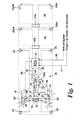
- a tractor 10 has front steerable wheels 11 which are steered by a hydraulic steering cylinder 12 control by a steering motor 13 operated by a steering wheel 14.
- the steering motor 13 is supplied with pressurised hydraulic fluid by a pump 15 from a reservoir 16.
- the wheels 11 can be turned through an angle ⁇ by admitting pressurised fluid into one end or the other of steering cylinder 12 via line 17 or 18 to displace piston 19 within cylinder 12 and hence turn steering knuckles 20 about their pivot axes 21 from their solid line straight ahead position to their turned dotted line positions 20'.
- the tractor 10 is also provided with left and right turn indicators 23 and 24 which are controlled by the normal manually operated turn indicator unit 25 operated by a lever 25a mounted on the steering wheel column 26.
- This turn indicator unit 25 uses the conventional mechanical reset for the indicators 23,24 using a pin or other member which turns with the steering wheel 14 and mechanically switches the indicators off in an automatic manner.
- an electronic control unit 27 which receives inputs from a steering angle sensor 28 via line 29, a vehicle speed signal via line 30 and a signal indicative as to whether one or two trailers are connected to the tractor via line 31.
- Figure 1 shows an arrangement in which a first trailer 32 and a second trailer 33 are connected with the tractor and these trailers have electrical connectors 32a and 33a by which the turn indicators 32bL, 32bR and 33bL, 33bR of these trailers are connected with the electronic control unit 27 on the tractor.
- the left and right turn indicators 23 and 24 of the tractor are also connected with electronic control unit 27 via lines 34 and 35 respectively.
- the signal in line 31 as to whether the tractor is towing one or two trailers could be provided automatically if connectors 32a and 33a are in use or could be provided manually by the tractor driver.
- the electronic control unit 27 operates using the following control algorithm:-
- the actual lengths of the trailers can be entered into the electronic control unit 27 manually by the driver or the control unit can assume a default value of say 5 metres for each trailer and the control unit will also apply an additional safety margin of 2 metres for each trailer giving default values of L1 and L2 of 7 metres each.
- electrical connectors 32a and 33a can form part of a known form of trailer recognition system which notifies the tractor as to exactly what type of trailer is connected and which, for example, identifies its length.
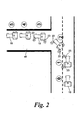
- FIG. 2 this shows a.tractor 10 making a left hand turn into a side road 40.
- Five positions of the tractor are shown. In position 0 the tractor is driving straight ahead on the road and the steering angle is about 0 degrees. At position 1 the driver operates the signal lever 25a to activate the mechanical turn indicator unit 25 which switches on the left turn indicators 23 and the steering angle is again approximately 0 degrees.
- the tractor is turning and the steering angle sensed by sensor 28 exceeds the first predetermined level of 12 degrees so that the electronic control unit is activated to control the turning-off of the turn indicators.
- the steering angle is still greater than 3.5 degrees and the turn indicators 23 are therefore still flashing.
- the turn is almost complete and the steering angle is less than 3.5 degrees and the electronic control unit has turned off the turn indicators 23.
- the turn indicating procedure is finished and the steering angle is again approximately 0 degrees as at position 0. The above described procedure is for a straight forward turn with a steering angle in excess of 12 degrees.
- the tractor pulls out into the other lane to begin the overtaking manoeuvre with the turn indicators 23 flashing and a steering angle of less than 12 degrees so that the operation of the electronic control unit 27 to take over the turning-off of the turn indicators is not activated.
- the tractor is opposite the vehicle 41 which is to be overtaken with the indictors 23 still flashing and the steering angle at approximately 0 degrees.
- the tractor moves back into its normal road lane with the right turn indicators 24 flashing and at a steering angle of less than 12 degrees.
- the overtaking manoeuvre is complete and the turn indicators have been turned-off either automatically by the unit 25 or manually using the lever 25a and the tractor is in a similar position to that shown at position 0.
- Figure 4 shows the position which a left turn is being made into a side road 42 using an overtaking lane 43 with seven positions of the tractor being shown.
- the tractor 10 is driving in the straight ahead position with a steering angle of approximately 0 degrees.
- the driver initiates operation of the turn indicators 23 using lever 25a to indicate that he is about to turn to the left into side road 42 and the steering angle is still approximately 0 degrees.
- the tractor steers into the turn lane 43 with the indicators 23 still flashing with a turn angle of less then 12 degrees so that the electronic control unit is not activated to take over the switching off of the flashing indicators.
- the tractor is driving in the straight ahead position in the turn lane 43 with the indicators 23 still flashing and the steering angle of approximately 0 degrees.
- the tractor commences the turn into the side road 43 with the indicators 23 still flashing and the turn angle now exceeds 12 degrees so the electronic control unit is activated to take over the switching off of the flashing indicators 23.
- the turn into the side road is not yet complete and the steering angle is still more than 3.5 degrees so that the indicators 23 continue to flash.
- the steering angle is now below 3.5 degrees and the electronic control unit has switched off the turn indicators 23.
- the turn is complete and the steering angle is approximately 0 degrees corresponding to the condition of position 0.
- the deactivation of the indicators by the electronic control unit it delayed in accordance with the details section 4 of the above described control algorithm. This delay takes account of both the length of the tractor and trailers and the velocity at which the tractor is moving. Thus ensuring that the indicators are not prematurely deactivated which could be potentially dangerous.
- the invention has been described above in relation to a tractor in which the wheels are turned by a hydraulic cylinder 12 with no direct mechanical connection between the movements of the steering wheel and the steering wheels of the vehicle, the invention is generally applicable to long vehicles such as long commercial lorries etc and, once the operation of the electronic control unit to switch off the turn indicators has been activated, the time period during which the turn indicators remain flashing can be extended to take into account the extreme length and/or speed of the commercial vehicle.
- the mechanical deactivation means is omitted and the control means receives a signal indicative as to whether the vehicle is towing one or more trailers and adjusts the length of operation of the turn indicator to take account of trailer length.
- a turn indicator system for a vehicle with steerable wheels.
- the system comprises a manual turn indicator initiating means to manually activate or deactivate the operation of turn indicators, mechanical deactivation means linked to a steering wheel to deactivate the indicators automatically, and sensing means to sense the steering angle of the wheels.
- Electronic control means are provided to receive the steering angle signal and switch the de-activation of the operation of the turn indicators to electronic control when the steering angle signal exceeds a first predetermined value. When under electronic control any deactivation demand from the mechanical deactivation means is disregarded and electronic deactivation only occurs when the steering angle signal falls to a second predetermined value.
Landscapes
- Engineering & Computer Science (AREA)
- Mechanical Engineering (AREA)
- Lighting Device Outwards From Vehicle And Optical Signal (AREA)
Claims (7)
- Abbiege-Indikator-System für ein Fahrzeug mit lenkbaren Rädern (11) mit- Abbiege-Indikatoren (23, 24) für ein Abbiegen nach rechts und links,- einem manuellen Abbiege-Indikator-Initiierungs-Mittel (25, 25a) zur manuellen Aktivierung und Deaktivierung des Betriebs der Abbiege-Indikatoren,- mindestens einem Deaktivierungs-Mittel zum Deaktivieren der Indikatoren;- mindestens einem sensierenden Mittel (28) zum Sensieren des Lenkwinkels der Räder (11), und- mindestens einem elektronischen Steuerungs- oder Regelungs-Mittel (27), welches das Lenkwinkelsignal empfängt und die Deaktivierung des Betriebs der Abbiege-Indikatoren (23, 24) steuert oder regelt,
dadurch gekennzeichnet, dass mechanische Deaktivierungs-Mittel mit einem Lenkrad (14) zum automatischen Deaktivieren der Indikatoren verbunden oder gekoppelt sind und dass das elektronische Steuerungs- oder Regelungsmittel (27) die Deaktivierung der Abbiege-Indikatoren (23, 24) zu der elektronischen Steuerung oder Regelung schaltet, wenn der Lenkwinkel einen ersten vorbestimmten Wert überschreitet, und den Betrieb der Abbiege-Indikatoren deaktiviert, wenn der Lenkwinkel auf einen zweiten vorbestimmten Wert fällt. - Abbiege-Indikator-System nach Anspruch 1, dadurch gekennzeichnet, dass das Steuerungs- oder Regelungsmittel (27) ein Signal (30) empfängt, welches von der Fahrzeuggeschwindigkeit abhängt oder diese indiziert und die Länge des Betriebs des Abbiege-Indikators in Abhängigkeit von der Fahrzeuggeschwindigkeit anpasst.
- Abbiege-Indikator-System nach Anspruch 1 oder 2, dadurch gekennzeichnet, dass das Steuerungs- oder Regelungsmittel (27) ein Signal (31, 32a, 33a) empfängt, welches abhängt davon, ob das Fahrzeug einen oder mehrere Anhänger (32, 33) zieht, oder welches dieses indiziert, und die Länge des Betriebs des Abbiege-Indikators anpasst, um die Anhängerlänge zu berücksichtigen.
- Abbiege-Indikator-System nach Anspruch 3, dadurch gekennzeichnet, dass der Fahrer oder Betreiber des Fahrzeugs die Länge des Anhängers oder der Anhänger, der oder die von dem Fahrzeug gezogen wird oder werden, in das Steuerungs- oder Regelungsmittel (27) eingeben kann.
- Abbiege-Indikator-System nach Anspruch 3, dadurch gekennzeichnet, dass das Steuerungs- oder Regelungsmittel (27) automatisch eine Default-Länge für den oder jeden Anhänger setzt.
- Abbiege-Indikator-System nach Anspruch 4 oder 5, dadurch gekennzeichnet, dass das Steuerungs- oder Regelungsmittel (27) automatisch die gesetzte Länge oder die Default-Länge des oder jedes Trailers um eine vorbestimmte Sicherheitsspanne erhöht.
- Abbiege-Indikator-System nach Anspruch 3, dadurch gekennzeichnet, dass das Steuerungs- oder Regelungsmittel (27) ein Signal von einem automatischen Anhänger-Erkennungs-System empfängt, welches die Länge des oder jedes Trailers, der mit dem Fahrzeug verbunden ist, indiziert.
Applications Claiming Priority (1)
| Application Number | Priority Date | Filing Date | Title |
|---|---|---|---|
| GB0713834A GB2451085A (en) | 2007-07-17 | 2007-07-17 | Long vehicle turn indicators |
Publications (3)
| Publication Number | Publication Date |
|---|---|
| EP2017125A2 EP2017125A2 (de) | 2009-01-21 |
| EP2017125A3 EP2017125A3 (de) | 2009-08-05 |
| EP2017125B1 true EP2017125B1 (de) | 2011-11-02 |
Family
ID=38476410
Family Applications (1)
| Application Number | Title | Priority Date | Filing Date |
|---|---|---|---|
| EP08012918A Active EP2017125B1 (de) | 2007-07-17 | 2008-07-17 | Fahrrichtungsanzeige für Kraftfahrzeuge |
Country Status (3)
| Country | Link |
|---|---|
| EP (1) | EP2017125B1 (de) |
| AT (1) | ATE531568T1 (de) |
| GB (1) | GB2451085A (de) |
Families Citing this family (5)
| Publication number | Priority date | Publication date | Assignee | Title |
|---|---|---|---|---|
| GB2538281B (en) * | 2015-05-14 | 2018-10-17 | Lodgesons Ltd | Vehicle direction indicator auxiliary control |
| SE539851C2 (en) | 2015-06-09 | 2017-12-19 | Scania Cv Ab | A direction indicator control module |
| TWI569235B (zh) | 2015-12-09 | 2017-02-01 | 財團法人工業技術研究院 | 車輛轉向警示方法及車輛轉向警示裝置 |
| US11203287B2 (en) * | 2018-06-28 | 2021-12-21 | Paccar Inc | Camera-based automatic turn signal deactivation |
| US12043170B2 (en) * | 2019-02-25 | 2024-07-23 | Volvo Truck Corporation | Computer-implemented method for automatically deactivating the left or right turn signals of a vehicle at the end of a turn |
Family Cites Families (8)
| Publication number | Priority date | Publication date | Assignee | Title |
|---|---|---|---|---|
| US4333071A (en) * | 1980-08-07 | 1982-06-01 | Hiroshi Kira | Self-cancelling apparatus for vehicle turn indicators |
| US5260685A (en) * | 1992-03-20 | 1993-11-09 | Federal-Mogul Corporation | Time-delayed self-cancelling turn signal |
| US5528218A (en) * | 1992-07-22 | 1996-06-18 | Grote Industries, Inc. | Electronic self-canceling turn signal device |
| US5786754A (en) * | 1995-12-13 | 1998-07-28 | Trw Inc. | Method and apparatus for electronically cancelling a vehicle direction signal in an electric assist steering system |
| JPH1059062A (ja) * | 1996-08-19 | 1998-03-03 | Toyota Autom Loom Works Ltd | 産業車輌の方向指示装置 |
| DE19941308A1 (de) * | 1999-08-31 | 2001-03-01 | Opel Adam Ag | Schaltung zum automatischen Abschalten von Blinkleuchten |
| US7425890B2 (en) * | 2004-07-08 | 2008-09-16 | Komatsu Ltd. | Direction indicator |
| CN1757520A (zh) | 2004-10-04 | 2006-04-12 | 奥西-技术有限公司 | 喷墨打印机 |
-
2007
- 2007-07-17 GB GB0713834A patent/GB2451085A/en not_active Withdrawn
-
2008
- 2008-07-17 AT AT08012918T patent/ATE531568T1/de active
- 2008-07-17 EP EP08012918A patent/EP2017125B1/de active Active
Also Published As
| Publication number | Publication date |
|---|---|
| EP2017125A2 (de) | 2009-01-21 |
| GB0713834D0 (en) | 2007-08-29 |
| GB2451085A (en) | 2009-01-21 |
| ATE531568T1 (de) | 2011-11-15 |
| EP2017125A3 (de) | 2009-08-05 |
Similar Documents
| Publication | Publication Date | Title |
|---|---|---|
| EP1740400B1 (de) | Fahrassistenzsystem zum ankuppeln eines anhängers unter einsatz einer fahrzeugniveauregulierung | |
| EP2480443B1 (de) | Fahrerassistenzsystem für ein fahrzeug, fahrzeug mit einem fahrerassistenzsystem und verfahren zum unterstützen eines fahrers beim führen eines fahrzeugs | |
| EP2017125B1 (de) | Fahrrichtungsanzeige für Kraftfahrzeuge | |
| EP2288533B1 (de) | Fahrzeugfahrhilfesystem für spurwechselassistenz | |
| US5056905A (en) | Control system for automatic adjustment of the rearview mirror of a vehicle | |
| GB2217274A (en) | Automatic return of power steering system | |
| EP2774828B1 (de) | Verfahren, Steuersystem und Bremssystem zur Steuerung des Rückwärtsrangierens eines Gespannfahrzeugs | |
| EP2489531B1 (de) | Verfahren zur Fahrerunterstützung bei einem Andock-Vorgang eines Nutzfahrzeugs an einer Rampe | |
| JPH0195981A (ja) | トレラーの操縦装置 | |
| US10752289B2 (en) | Control system for steering a towing vehicle with a trailer | |
| EP2858879A1 (de) | Verfahren und system zur fahrspurverfolgungshilfe für ein fahrzeug | |
| US11332006B2 (en) | System for assisting the driving of a trailer from an open tipping hydraulic circuit | |
| CN121224682A (zh) | 用于辅助机动车与挂车的耦连过程的方法和系统 | |
| US20100013624A1 (en) | Turn signal device self cancelling feature | |
| WO2006029725A1 (de) | Einrichtung zur vorausschauenden kollisionserkennung und -vermeidung | |
| US5027917A (en) | Power-steering system | |
| CN110461142B (zh) | 包括设置有防撞击系统的牵引车和挂车机具的农业系统 | |
| DE19809892C2 (de) | Flurförderzeug mit Deichsellenkung | |
| JP2772485B2 (ja) | 遠隔作業用走行車における操向報知装置 | |
| EP2716523B1 (de) | Regelungssystem, und Verfahren in einem Regelungssystem | |
| EP1681203B1 (de) | Verfahren zum Rückstellen eines Fahrtrichtungsanzeigers eines Kraftfahrzeugs | |
| DE29913557U1 (de) | Rückspiegel mit automatischer Einstellung für Kraftfahrzeuge mit Anhänger | |
| WO2014079521A1 (de) | Verfahren und vorrichtung zur steuerung eines rückraumüberwachungssystems einer fahrzeugkombination | |
| CN111989253B (zh) | 倒车辅助系统 | |
| JP2597088Y2 (ja) | 連結車両の操舵装置 |
Legal Events
| Date | Code | Title | Description |
|---|---|---|---|
| PUAI | Public reference made under article 153(3) epc to a published international application that has entered the european phase |
Free format text: ORIGINAL CODE: 0009012 |
|
| AK | Designated contracting states |
Kind code of ref document: A2 Designated state(s): AT BE BG CH CY CZ DE DK EE ES FI FR GB GR HR HU IE IS IT LI LT LU LV MC MT NL NO PL PT RO SE SI SK TR |
|
| AX | Request for extension of the european patent |
Extension state: AL BA MK RS |
|
| PUAL | Search report despatched |
Free format text: ORIGINAL CODE: 0009013 |
|
| AK | Designated contracting states |
Kind code of ref document: A3 Designated state(s): AT BE BG CH CY CZ DE DK EE ES FI FR GB GR HR HU IE IS IT LI LT LU LV MC MT NL NO PL PT RO SE SI SK TR |
|
| AX | Request for extension of the european patent |
Extension state: AL BA MK RS |
|
| 17P | Request for examination filed |
Effective date: 20100205 |
|
| 17Q | First examination report despatched |
Effective date: 20100301 |
|
| AKX | Designation fees paid |
Designated state(s): AT BE BG CH CY CZ DE DK EE ES FI FR GB GR HR HU IE IS IT LI LT LU LV MC MT NL NO PL PT RO SE SI SK TR |
|
| GRAP | Despatch of communication of intention to grant a patent |
Free format text: ORIGINAL CODE: EPIDOSNIGR1 |
|
| GRAS | Grant fee paid |
Free format text: ORIGINAL CODE: EPIDOSNIGR3 |
|
| GRAA | (expected) grant |
Free format text: ORIGINAL CODE: 0009210 |
|
| AK | Designated contracting states |
Kind code of ref document: B1 Designated state(s): AT BE BG CH CY CZ DE DK EE ES FI FR GB GR HR HU IE IS IT LI LT LU LV MC MT NL NO PL PT RO SE SI SK TR |
|
| REG | Reference to a national code |
Ref country code: GB Ref legal event code: FG4D |
|
| REG | Reference to a national code |
Ref country code: CH Ref legal event code: EP |
|
| REG | Reference to a national code |
Ref country code: IE Ref legal event code: FG4D |
|
| REG | Reference to a national code |
Ref country code: DE Ref legal event code: R096 Ref document number: 602008010993 Country of ref document: DE Effective date: 20120112 |
|
| REG | Reference to a national code |
Ref country code: NL Ref legal event code: VDEP Effective date: 20111102 |
|
| LTIE | Lt: invalidation of european patent or patent extension |
Effective date: 20111102 |
|
| PG25 | Lapsed in a contracting state [announced via postgrant information from national office to epo] |
Ref country code: NO Free format text: LAPSE BECAUSE OF FAILURE TO SUBMIT A TRANSLATION OF THE DESCRIPTION OR TO PAY THE FEE WITHIN THE PRESCRIBED TIME-LIMIT Effective date: 20120202 Ref country code: LT Free format text: LAPSE BECAUSE OF FAILURE TO SUBMIT A TRANSLATION OF THE DESCRIPTION OR TO PAY THE FEE WITHIN THE PRESCRIBED TIME-LIMIT Effective date: 20111102 Ref country code: IS Free format text: LAPSE BECAUSE OF FAILURE TO SUBMIT A TRANSLATION OF THE DESCRIPTION OR TO PAY THE FEE WITHIN THE PRESCRIBED TIME-LIMIT Effective date: 20120302 |
|
| PG25 | Lapsed in a contracting state [announced via postgrant information from national office to epo] |
Ref country code: GR Free format text: LAPSE BECAUSE OF FAILURE TO SUBMIT A TRANSLATION OF THE DESCRIPTION OR TO PAY THE FEE WITHIN THE PRESCRIBED TIME-LIMIT Effective date: 20120203 Ref country code: LV Free format text: LAPSE BECAUSE OF FAILURE TO SUBMIT A TRANSLATION OF THE DESCRIPTION OR TO PAY THE FEE WITHIN THE PRESCRIBED TIME-LIMIT Effective date: 20111102 Ref country code: HR Free format text: LAPSE BECAUSE OF FAILURE TO SUBMIT A TRANSLATION OF THE DESCRIPTION OR TO PAY THE FEE WITHIN THE PRESCRIBED TIME-LIMIT Effective date: 20111102 Ref country code: BE Free format text: LAPSE BECAUSE OF FAILURE TO SUBMIT A TRANSLATION OF THE DESCRIPTION OR TO PAY THE FEE WITHIN THE PRESCRIBED TIME-LIMIT Effective date: 20111102 Ref country code: NL Free format text: LAPSE BECAUSE OF FAILURE TO SUBMIT A TRANSLATION OF THE DESCRIPTION OR TO PAY THE FEE WITHIN THE PRESCRIBED TIME-LIMIT Effective date: 20111102 Ref country code: PT Free format text: LAPSE BECAUSE OF FAILURE TO SUBMIT A TRANSLATION OF THE DESCRIPTION OR TO PAY THE FEE WITHIN THE PRESCRIBED TIME-LIMIT Effective date: 20120302 Ref country code: PL Free format text: LAPSE BECAUSE OF FAILURE TO SUBMIT A TRANSLATION OF THE DESCRIPTION OR TO PAY THE FEE WITHIN THE PRESCRIBED TIME-LIMIT Effective date: 20111102 Ref country code: SI Free format text: LAPSE BECAUSE OF FAILURE TO SUBMIT A TRANSLATION OF THE DESCRIPTION OR TO PAY THE FEE WITHIN THE PRESCRIBED TIME-LIMIT Effective date: 20111102 Ref country code: SE Free format text: LAPSE BECAUSE OF FAILURE TO SUBMIT A TRANSLATION OF THE DESCRIPTION OR TO PAY THE FEE WITHIN THE PRESCRIBED TIME-LIMIT Effective date: 20111102 |
|
| PG25 | Lapsed in a contracting state [announced via postgrant information from national office to epo] |
Ref country code: CY Free format text: LAPSE BECAUSE OF FAILURE TO SUBMIT A TRANSLATION OF THE DESCRIPTION OR TO PAY THE FEE WITHIN THE PRESCRIBED TIME-LIMIT Effective date: 20111102 |
|
| PG25 | Lapsed in a contracting state [announced via postgrant information from national office to epo] |
Ref country code: EE Free format text: LAPSE BECAUSE OF FAILURE TO SUBMIT A TRANSLATION OF THE DESCRIPTION OR TO PAY THE FEE WITHIN THE PRESCRIBED TIME-LIMIT Effective date: 20111102 Ref country code: CZ Free format text: LAPSE BECAUSE OF FAILURE TO SUBMIT A TRANSLATION OF THE DESCRIPTION OR TO PAY THE FEE WITHIN THE PRESCRIBED TIME-LIMIT Effective date: 20111102 Ref country code: SK Free format text: LAPSE BECAUSE OF FAILURE TO SUBMIT A TRANSLATION OF THE DESCRIPTION OR TO PAY THE FEE WITHIN THE PRESCRIBED TIME-LIMIT Effective date: 20111102 Ref country code: BG Free format text: LAPSE BECAUSE OF FAILURE TO SUBMIT A TRANSLATION OF THE DESCRIPTION OR TO PAY THE FEE WITHIN THE PRESCRIBED TIME-LIMIT Effective date: 20120202 Ref country code: DK Free format text: LAPSE BECAUSE OF FAILURE TO SUBMIT A TRANSLATION OF THE DESCRIPTION OR TO PAY THE FEE WITHIN THE PRESCRIBED TIME-LIMIT Effective date: 20111102 |
|
| PG25 | Lapsed in a contracting state [announced via postgrant information from national office to epo] |
Ref country code: RO Free format text: LAPSE BECAUSE OF FAILURE TO SUBMIT A TRANSLATION OF THE DESCRIPTION OR TO PAY THE FEE WITHIN THE PRESCRIBED TIME-LIMIT Effective date: 20111102 |
|
| PLBE | No opposition filed within time limit |
Free format text: ORIGINAL CODE: 0009261 |
|
| STAA | Information on the status of an ep patent application or granted ep patent |
Free format text: STATUS: NO OPPOSITION FILED WITHIN TIME LIMIT |
|
| REG | Reference to a national code |
Ref country code: AT Ref legal event code: MK05 Ref document number: 531568 Country of ref document: AT Kind code of ref document: T Effective date: 20111102 |
|
| 26N | No opposition filed |
Effective date: 20120803 |
|
| REG | Reference to a national code |
Ref country code: DE Ref legal event code: R097 Ref document number: 602008010993 Country of ref document: DE Effective date: 20120803 |
|
| PG25 | Lapsed in a contracting state [announced via postgrant information from national office to epo] |
Ref country code: AT Free format text: LAPSE BECAUSE OF FAILURE TO SUBMIT A TRANSLATION OF THE DESCRIPTION OR TO PAY THE FEE WITHIN THE PRESCRIBED TIME-LIMIT Effective date: 20111102 |
|
| PG25 | Lapsed in a contracting state [announced via postgrant information from national office to epo] |
Ref country code: MC Free format text: LAPSE BECAUSE OF NON-PAYMENT OF DUE FEES Effective date: 20120731 |
|
| REG | Reference to a national code |
Ref country code: CH Ref legal event code: PL |
|
| PG25 | Lapsed in a contracting state [announced via postgrant information from national office to epo] |
Ref country code: LI Free format text: LAPSE BECAUSE OF NON-PAYMENT OF DUE FEES Effective date: 20120731 Ref country code: CH Free format text: LAPSE BECAUSE OF NON-PAYMENT OF DUE FEES Effective date: 20120731 Ref country code: ES Free format text: LAPSE BECAUSE OF FAILURE TO SUBMIT A TRANSLATION OF THE DESCRIPTION OR TO PAY THE FEE WITHIN THE PRESCRIBED TIME-LIMIT Effective date: 20120213 |
|
| REG | Reference to a national code |
Ref country code: IE Ref legal event code: MM4A |
|
| PG25 | Lapsed in a contracting state [announced via postgrant information from national office to epo] |
Ref country code: FI Free format text: LAPSE BECAUSE OF FAILURE TO SUBMIT A TRANSLATION OF THE DESCRIPTION OR TO PAY THE FEE WITHIN THE PRESCRIBED TIME-LIMIT Effective date: 20111102 |
|
| PG25 | Lapsed in a contracting state [announced via postgrant information from national office to epo] |
Ref country code: IE Free format text: LAPSE BECAUSE OF NON-PAYMENT OF DUE FEES Effective date: 20120717 Ref country code: MT Free format text: LAPSE BECAUSE OF FAILURE TO SUBMIT A TRANSLATION OF THE DESCRIPTION OR TO PAY THE FEE WITHIN THE PRESCRIBED TIME-LIMIT Effective date: 20111102 |
|
| PG25 | Lapsed in a contracting state [announced via postgrant information from national office to epo] |
Ref country code: TR Free format text: LAPSE BECAUSE OF FAILURE TO SUBMIT A TRANSLATION OF THE DESCRIPTION OR TO PAY THE FEE WITHIN THE PRESCRIBED TIME-LIMIT Effective date: 20111102 |
|
| PG25 | Lapsed in a contracting state [announced via postgrant information from national office to epo] |
Ref country code: LU Free format text: LAPSE BECAUSE OF NON-PAYMENT OF DUE FEES Effective date: 20120717 |
|
| PG25 | Lapsed in a contracting state [announced via postgrant information from national office to epo] |
Ref country code: HU Free format text: LAPSE BECAUSE OF FAILURE TO SUBMIT A TRANSLATION OF THE DESCRIPTION OR TO PAY THE FEE WITHIN THE PRESCRIBED TIME-LIMIT Effective date: 20080717 |
|
| REG | Reference to a national code |
Ref country code: FR Ref legal event code: PLFP Year of fee payment: 9 |
|
| REG | Reference to a national code |
Ref country code: FR Ref legal event code: PLFP Year of fee payment: 10 |
|
| PGFP | Annual fee paid to national office [announced via postgrant information from national office to epo] |
Ref country code: AT Payment date: 20170522 Year of fee payment: 12 |
|
| REG | Reference to a national code |
Ref country code: FR Ref legal event code: PLFP Year of fee payment: 11 |
|
| GBPC | Gb: european patent ceased through non-payment of renewal fee |
Effective date: 20180717 |
|
| PG25 | Lapsed in a contracting state [announced via postgrant information from national office to epo] |
Ref country code: GB Free format text: LAPSE BECAUSE OF NON-PAYMENT OF DUE FEES Effective date: 20180717 |
|
| PG25 | Lapsed in a contracting state [announced via postgrant information from national office to epo] |
Ref country code: IT Free format text: LAPSE BECAUSE OF NON-PAYMENT OF DUE FEES Effective date: 20180717 |
|
| P01 | Opt-out of the competence of the unified patent court (upc) registered |
Effective date: 20230518 |
|
| PGFP | Annual fee paid to national office [announced via postgrant information from national office to epo] |
Ref country code: DE Payment date: 20250722 Year of fee payment: 18 |
|
| PGFP | Annual fee paid to national office [announced via postgrant information from national office to epo] |
Ref country code: FR Payment date: 20250724 Year of fee payment: 18 |