EP2017210A2 - Procédé destiné au fonctionnement d'un appareil de pliage en longueur - Google Patents
Procédé destiné au fonctionnement d'un appareil de pliage en longueur Download PDFInfo
- Publication number
- EP2017210A2 EP2017210A2 EP08153403A EP08153403A EP2017210A2 EP 2017210 A2 EP2017210 A2 EP 2017210A2 EP 08153403 A EP08153403 A EP 08153403A EP 08153403 A EP08153403 A EP 08153403A EP 2017210 A2 EP2017210 A2 EP 2017210A2
- Authority
- EP
- European Patent Office
- Prior art keywords
- printed product
- speed
- folding
- control unit
- value
- Prior art date
- Legal status (The legal status is an assumption and is not a legal conclusion. Google has not performed a legal analysis and makes no representation as to the accuracy of the status listed.)
- Granted
Links
- 238000000034 method Methods 0.000 title claims abstract description 54
- 238000004519 manufacturing process Methods 0.000 claims description 19
- 230000008569 process Effects 0.000 claims description 10
- 239000000758 substrate Substances 0.000 claims description 5
- 230000003287 optical effect Effects 0.000 claims description 3
- 230000003028 elevating effect Effects 0.000 claims description 2
- 238000011156 evaluation Methods 0.000 claims description 2
- 238000000691 measurement method Methods 0.000 claims description 2
- 238000012545 processing Methods 0.000 claims description 2
- 230000033001 locomotion Effects 0.000 description 18
- 239000000463 material Substances 0.000 description 5
- 230000001419 dependent effect Effects 0.000 description 4
- 238000005259 measurement Methods 0.000 description 4
- 238000011144 upstream manufacturing Methods 0.000 description 4
- 230000000712 assembly Effects 0.000 description 3
- 238000000429 assembly Methods 0.000 description 3
- 230000001276 controlling effect Effects 0.000 description 3
- 238000010586 diagram Methods 0.000 description 3
- 230000006870 function Effects 0.000 description 3
- 238000012546 transfer Methods 0.000 description 3
- 230000009471 action Effects 0.000 description 2
- 230000007246 mechanism Effects 0.000 description 2
- 230000000284 resting effect Effects 0.000 description 2
- 241001236093 Bulbophyllum maximum Species 0.000 description 1
- 230000006978 adaptation Effects 0.000 description 1
- 230000004888 barrier function Effects 0.000 description 1
- 230000008901 benefit Effects 0.000 description 1
- 230000008859 change Effects 0.000 description 1
- 238000010276 construction Methods 0.000 description 1
- 238000005336 cracking Methods 0.000 description 1
- 238000001514 detection method Methods 0.000 description 1
- 238000011161 development Methods 0.000 description 1
- 230000000694 effects Effects 0.000 description 1
- 238000004134 energy conservation Methods 0.000 description 1
- 230000001788 irregular Effects 0.000 description 1
- 230000002093 peripheral effect Effects 0.000 description 1
- 230000009467 reduction Effects 0.000 description 1
- 230000001105 regulatory effect Effects 0.000 description 1
- 238000004904 shortening Methods 0.000 description 1
- 238000013519 translation Methods 0.000 description 1
Images


Classifications
-
- B—PERFORMING OPERATIONS; TRANSPORTING
- B65—CONVEYING; PACKING; STORING; HANDLING THIN OR FILAMENTARY MATERIAL
- B65H—HANDLING THIN OR FILAMENTARY MATERIAL, e.g. SHEETS, WEBS, CABLES
- B65H45/00—Folding thin material
- B65H45/12—Folding articles or webs with application of pressure to define or form crease lines
- B65H45/18—Oscillating or reciprocating blade folders
-
- B—PERFORMING OPERATIONS; TRANSPORTING
- B65—CONVEYING; PACKING; STORING; HANDLING THIN OR FILAMENTARY MATERIAL
- B65H—HANDLING THIN OR FILAMENTARY MATERIAL, e.g. SHEETS, WEBS, CABLES
- B65H29/00—Delivering or advancing articles from machines; Advancing articles to or into piles
- B65H29/68—Reducing the speed of articles as they advance
-
- B—PERFORMING OPERATIONS; TRANSPORTING
- B65—CONVEYING; PACKING; STORING; HANDLING THIN OR FILAMENTARY MATERIAL
- B65H—HANDLING THIN OR FILAMENTARY MATERIAL, e.g. SHEETS, WEBS, CABLES
- B65H9/00—Registering, e.g. orientating, articles; Devices therefor
- B65H9/14—Retarding or controlling the forward movement of articles as they approach stops
-
- B—PERFORMING OPERATIONS; TRANSPORTING
- B65—CONVEYING; PACKING; STORING; HANDLING THIN OR FILAMENTARY MATERIAL
- B65H—HANDLING THIN OR FILAMENTARY MATERIAL, e.g. SHEETS, WEBS, CABLES
- B65H2301/00—Handling processes for sheets or webs
- B65H2301/30—Orientation, displacement, position of the handled material
- B65H2301/33—Modifying, selecting, changing orientation
- B65H2301/331—Skewing, correcting skew, i.e. changing slightly orientation of material
-
- B—PERFORMING OPERATIONS; TRANSPORTING
- B65—CONVEYING; PACKING; STORING; HANDLING THIN OR FILAMENTARY MATERIAL
- B65H—HANDLING THIN OR FILAMENTARY MATERIAL, e.g. SHEETS, WEBS, CABLES
- B65H2513/00—Dynamic entities; Timing aspects
- B65H2513/10—Speed
Definitions
- the invention relates to a method for operating a longitudinal folding apparatus according to the preamble of claim 1.
- a longitudinal folding apparatus with a relative to a folding table up and down folding blade wherein the folding blade is mounted on at least one pivotable relative to the folding table lever, wherein the longitudinal folder has a movable stop, which slows down a run into the longitudinal folder pressure printed product this stop is movable along the braking distance of the printed products at a speed lower than the input speed.
- a sensor detects an input speed at which the printed product enters the longitudinal folding apparatus.
- a control unit synchronizes, based on the sensor signal, the rotational movement of two disks at the determined speed of the printed product in such a way that that this printed product meets at the entrance of a braking distance on a cam of the discs, wherein the cams move slower than the determined speed of the printed product, so that the printed product is braked by the cam.
- the braking distance is limited by one of the surface of the folding table facing lateral surface of the two discs.
- the cams act for the incoming in the L jossfalzapparat printed product in each case as a movable stop, which controls the input speed of the printed product z. B. reduced by 10%.
- the printed product comes after another deceleration z. B. by brake brushes finally against a fixed stop.
- a folding apparatus with a brake brush brake assembly for braking folded copies is known, the folded copies strike with their front edges against stops, and with a folding blade or a folding blade for folding the folded copies, wherein at the stops and / or in the vicinity of the attacks sensors for determining the deformation of the folded copies are arranged and that a control device controls the position and / or the movement of the brake assemblies and / or the movement of the folding blade or the folding blade due to the measured position of the folded copies via a servomotor.
- a device for braking paper sheets which acts on the trailing edge of the paper sheets, wherein at least one resiliently movable brake shoe is provided by the force of a Electromagnet acts on the paper sheet.
- a folding machine for a printing press with a folding table is known to form a sheet parallel to the transport direction of the same extending longitudinal fold on sheet or on a sheet-shaped substrate copies, wherein the folding table at least one braking device is assigned to the movement of the sheet or copies in the Decelerate the area of the folding table, wherein the or each braking device is preferably designed as a brake brush.
- Longitudinal folders are used in the printing industry, especially in the final production of printed products, the printed products are pressed by a folding blade in a folding gap and folded in this longitudinally. Because the direction of entry of the printed products into the longitudinal folder is transverse to their subsequent movement through the nip, they must be decelerated prior to their passage through the nip. For this purpose, it is known to arrange in a L Lucassfalzapparat brake brushes, which gradually decelerate the incoming printed products by friction. Moreover, it is known to provide in a longitudinal folder usually a plurality of fixed stops against which abut the printed products in their continued in the feed direction transport, whereby they are abruptly braked.
- the brushes In order to avoid damage to the printed products at this stop, their speed must be reduced by the brushes to a low value, but this value must not be zero, because then the printed products do not reach this stop reliably and it comes in the longitudinal folder to a jam of successively transported printed products.
- the extent of the deceleration by the brushes is determined by the frictional force they exert on the printed matter, and thus by their position. If at the same position of the brushes printed products of different thickness to be folded, so the friction increases with the thickness of the printed products strongly, so that a thick print may get stuck between the brushes and fail to reach the stopper, while a thin print might bounce off the stopper at high speed, damaging it. Therefore, the position of the brushes is usually adapted to the thickness of the printed products.
- the friction between a printed product and the brushes also depends on the surface finish of the printed product. Smooth paper can strike the fence at too high a speed, while equally thick and equally dense printed paper from rough paper may not reach the fence.
- the position of the brushes must therefore be adapted to virtually every print job to ensure proper functioning of the L jossfalzapparats. Due to the variety of influencing parameters, adaptation can often only be done empirically, which involves a great deal of time and costs.
- the invention has for its object to provide a method for operating a longitudinal folder, which leads in the longitudinal folder to a gentler and thus improved treatment of a longitudinal to be folded printed product.
- the achievable with the present invention consist in particular in that the product quality on the one hand and the reliability (availability) of the folder on the other hand is significantly increased because the impact energy, ie the kinetic energy with which a longitudinal to be folded printed product against a his transport path limiting, arranged in L Lucassfalzapparat stop bounces, is kept within acceptable limits.
- a permissible limit is defined by the deformation work exerted on the printed product as a result of its impact on the stop acting as a rigid wall, which due to the energy conservation and the Momentum conservation, ie almost alone to be absorbed by this printed matter, does not lead to breakage, ie not to tearing of the material, dhid R. the paper of this printed product.
- the impact energy of the printed product always has an amount greater than zero, since this printed product is both massive and at a speed greater than zero abuts against the stop, ie it is in the longitudinal folder in motion and should reach the stop reliably due to its movement.
- the mass of the printed product is z. B. depending on the type of paper used and its number of sheets and thus variable.
- the executed by the printed product along a folding table of Lijnsfalzapparates movement is preferably a translational movement.
- this longitudinal folder 01 is preferably arranged in a folding machine downstream of a printing press or there at least can be arranged.
- the printing machine can be designed as a sheet-fed printing press or as a web-fed printing machine.
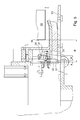
- the longitudinal folder 01 has a z. B. arranged on a frame 02 folding table 03 with a flat support surface in which a folding gap 04 is formed, wherein the folding gap 04 in the transport direction T of the folding table 03 to be fed, longitudinally to be folded printed product 21 extends.
- the printed product 21 itself is for reasons of clarity only in the Fig. 3 shown.
- the folding blade 06 is z. B. at least one about a pivot point 08, z. B. an axis 08 pivotable lever 07 is arranged, wherein the lever 07 and thus also attached to him folding blade 06 in a certain time a in the Fig. 1 executed by a double arrow indicated pivoting movement, wherein the clock frequency is preferably set by one or at least by means of a control unit 26 ( Fig. 2 ).
- the lever 07 is preferably in the transport direction T of the folding table 03 to be supplied printed product 21 executed twice ( Fig. 3 ).
- Fig. 2 shows a schematic sectional view of the in the Fig. 1 It can be seen that a printed product 21 pressed by the folding blade 06 into the folding gap 04 is gripped and folded below the folding table 03 by a pair of folding rollers 09. Thereafter, the folded printed product 21 z. B. led by a belt system 13 is preferably first promoted to a paddle wheel 11 and designed by this on a delivery device 12, or it can be provided that the folded printed product 21 - as in the Fig. 2 shown in dashed lines - otherwise discharged from the longitudinal folder 01.
- the folding blade 06 is preferably driven by a cam mechanism.
- the lever 07 may be formed either a lever arm of a lever designed as a double lever with a second lever arm 14 or as a one-armed lever, in which case with the rotatably mounted axle 08, a second lever 14 is rotatably connected.
- a cam 16 acting stop 17, z. B. as rotatably mounted on the lever 14 roller 17, arranged.
- the cam 16 is rotatably mounted on a shaft 18 which directly or via a gear through a only schematically indicated drive 19, z. B.
- a motor 19, is rotationally driven.
- the drive 19 is z. B. controlled or regulated by a control unit 26.
- the cam 16 may have an irregular and asymmetrical with respect to its axis of rotation curved line, which then causes a rotation of the crank mechanism (lever 07 and 14) a corresponding movement of the folding blade 06.
- the cam 16 is formed as a circular disk with a circular peripheral line, which, however, is arranged eccentrically on the shaft 18.
- a regulation of the touch contact of the ink knife 06 with a longitudinally to be folded printed product 21 (FIG. Fig. 3 ) is the angular position of the cam 16, the relevant actuator.
- the cam 16 also determines one of the folding blade 06 on the Folding table 03 executed stroke, which, among other things, a thickness of the longitudinal to be folded printed product 21 is adjusted.
- Fig. 3 shows in a perspective view a section of the in the Fig. 1 shown longitudinal folder 01, wherein the longitudinal to be folded printed product 21, z. B. a sheet or a separated from a sheet-like substrate copy, which has a length L21 in its transport direction T, the folding table 03 is fed by means of a transport system, not shown and is now moved along the folding table 03 in the transport direction T of the printed product 21, wherein the Folding table 03 in the transport direction T of the printed product 21 has a length L03.
- the folding blade 06 which in the transport direction T of the printed product 21 has a length L06, by the drive of the lever 07 and the associated pivotal movement about the fulcrum 08 from the folding table 03 initially pivoted.
- the longitudinally to be folded printed product 21 now moves under the folding blade 06 sliding in a straight line continuation of its transport direction T to this transport path limiting stop 22, wherein the stop 22 may consist of a plurality of orthogonal to the support surface of the folding table 03 rigid boundary surfaces. These boundary surfaces are z. B. arranged close to a length L03 of the folding table 03 limiting edge 32 of its support surface in a row spaced from each other.
- the stopper 22 is thus preferably formed stationary with respect to the folding table 03.
- the folding blade 06 passes through a lowering in the direction of the support surface of the folding table 03 with the along the folding table 03 on the stop 22 zugewandten printed product 21 in a touching contact, even before this printed product 21 reaches the stop 22.
- the printed product 21 to be folded longitudinally can be single or multi-layered and thus have different thicknesses.
- the length L03 of the folding table 03, the length L06 of the folding blade 06 and the length L21 of the printed product 21 are all rectified, namely in the transport direction T of the printed product 21, wherein the length L06 of the folding blade 06 preferably at least equal to the length L21 of the printed product 21 and wherein Both the length L21 of the printed product 21 and the length L06 of the folding knife 06 are each smaller than the length L03 of the folding table 03.
- the length L06 of the folding knife 06 determines the maximum braking distance that the folding blade 06 can exert by its touch contact with the printed product 21 .
- a length of the running of the printed product 21 along the length L06 of the folding blade 06 and thus effective to decelerate the moving printed product 21 is also effective Set braking distance, wherein this braking distance can assume a value between zero and the length L06 of the folding blade 06 corresponding maximum value.
- An influence of the braking effect is therefore not effected by a change of a folding blade 06 applied to the printed product 21 contact pressure, but decisive for the length of the braking distance is a relevant for the sliding friction and z.
- the force exerted by the folding blade 06 during the braking process on the printed product 21 is assumed to be constant, d. H. it remains unchanged during the braking process in their respective value.
- Fig. 4 shows in a magnification a section of the in the Fig. 3 shown part of the longitudinal folding apparatus 01, wherein the transport path of the printed product 21 delimiting boundary surfaces of the stopper 22 are highlighted. These boundary surfaces of the stopper 22 are provided orthogonal to the bearing surface of the folding table 03 on both sides of the folding gap 04.
- the stop 22 can at a orthogonal to the extension of the folding gap 04 aligned traverse 23 may be attached.
- the stop 22 upstream in the transport direction T of the printed product 21, a sensor assembly 24 is provided, preferably a sensor assembly 24 is provided to each of the folding gap 04 each, then both sensor assemblies 24 z. B. designed to be identical and are arranged above all in the same distance in front of one of the boundary surfaces of the stopper 22.
- a arranged on both sides of the folding gap 04 sensor assembly 24 has the advantage that with her a possible imbalance of the printed product 21 can be detected on the folding table 03, so that measures for correcting the position of the printed product 21 can be initiated if necessary.
- the sensor arrangement 24 detects at least the speed of the printed product 21 moved in the transport direction T and preferably uses an optical measuring method for this detection.
- the sensor arrangement 24 passes its respective measurement signals to the control unit 26, which in turn controls or regulates the drive 19 of the cam 16 and thus ultimately also the time for the start of a frictional engagement of the folding blade 06 with the printed product 21 ( Fig. 2 ).
- Fig. 5 shows in a longitudinal section one of the in the Fig. 4 shown sensor assemblies 24.
- the sensor assembly 24 preferably has two in the transport direction T of the printed product 21 successively arranged sensor elements 27; 28 on which each z. B. as a directed onto the support surface of the folding table 03 diffuse reflection sensor or as a component of the printed product 21 to be passed through a light barrier, wherein the sensor elements 27; 28 as a light source z. B. each use at least one light emitting diode or laser diode.
- Both successively arranged sensor elements 27; 28 mark in extension of their respective measuring axis 29; 31 on the bearing surface of the folding table 03 a fixed length in its length measuring section M, wherein the length of the measuring path M z. B.
- the measuring section M ends with respect to an impact on the stop 22 moved printed product 21 at a fixed distance A in front of one of the boundary surfaces of this stop 22.
- a point of impact of the printed product 21 in the transport direction T first traversed first measuring axis 29 on the support surface of the folding table 03 is one of the boundary surfaces of the stop 22nd z. B. in the range between 10 mm and 20 mm spaced, preferably in the range between 15 mm and 18 mm.
- An impact point of the printed product 21 in the transport direction T as the second traversed second measuring axis 31 on the support surface of the folding table 03 is of one of the boundary surfaces of the stopper 22 z. B. in the range between 1 mm and 10 mm, preferably in the range between 3 mm and 5 mm.
- the folding table 03 of this longitudinal folder 01 is z. B. by means of a (not shown) upstream conveyor belt a longitudinally folding printed product 21 with a first variable, usually high speed supplied, said first speed of the printed product 21 whose input speed is in the longitudinal folder 01 and respectively in the transport direction T of the printed product 21 seen z. B. at the beginning of a predetermined by the length L03 of the folding table 03 section or at the beginning of a particular by the length L06 of the folding blade 06 section is present, the beginning of each of these sections is defined by a seen in the transport direction T leading edge 33 of the printed product 21 reaches the relevant section and then enters it.
- This first speed of the printed product 21 is reduced by a frictional engagement preferably with the folding blade 06 to a second speed, while the printed product 21 moves along the folding table 03, wherein the first speed of the printed product 21 regardless of their value when reaching the folding table 03 by a variable adjustable beginning of the force exerted on the printed product 21 frictional engagement is always reduced to the same predetermined second speed.
- This reduction in speed of the printed product 21 is made while the printed product 21 moving along the folding table 03 moves toward the stop 22 delimiting its transport path.
- the frictional engagement exerted on the printed product 21 reduces the first speed of the printed product 21 to its second speed before the printed product 21 strikes the stop 22 delimiting its transport path.
- this printed product 21 In order to be able to process a longitudinally to be folded printed product 21 in the longitudinal folder 01, this printed product 21 must be stopped completely with respect to its directed to the stop 22 speed component before it can be pressed by the folding blade 06 through the folding gap 04.
- the longitudinally to be folded printed product 21 should therefore be controlled by its impact on the stop 22 braked to its standstill. Only then does the actual process of longitudinal folding begin.
- a complete deceleration of the longitudinally to be folded printed product 21 by its impact on the stop 22 is ensured if the longitudinal to be folded printed product 21 in the defined distance A to the stop 22, the product and / or production-specific second speed, which second speed in Movement printed product 21 should not exceed within a tolerable tolerance and should not fall below.
- the second speed thus does not necessarily have to be defined by a single value, but may also have a certain, albeit preferably narrow, bandwidth of e.g. B. maximum ⁇ 10% of the nominal value of this second speed.
- the first speed of the printed product 21 can generally assume different values in a wide range.
- the first speed of the printed product 21 is z. B. of a production speed of the printing process for the production of the printed product 21 exporting printing machine dependent.
- the first speed of the printed product 21 is also z. B. of a type of production of the printed product 21 processing folder depending on the type of production the folder z. B. relates to whether the longitudinal folder 01 a collected or an unsorted printed product 21 is supplied. Regardless of these dependencies, the first speed of the printed product 21 always has a higher value than its second speed. Since the printed product 21 with its leading edge 33 should reach the boundary surfaces of the stop 22 ( Fig. 3 ), the second speed of the printed product 21 has a value other than zero.
- the second speed of the printed product 21, whose product and / or production-related setpoint value is stored in the control unit 26, is kept constant within certain tolerances, so that the printed product 21 strikes with its front edge 33 at the boundary surfaces of the stopper 22 in a manner that the Printed product 21 not damaged.
- the force exerted by the stop 22 on the printed product 21 momentum transfer is to be limited and kept within such limits that can be used by the material of the printed product 21, d. H. the kinetic energy to be absorbed by the print product 21 through the impact process must not cause any forces which cause impermissible strains in the print product 21, such forces being impermissible which plastically deform and / or tear the print product 21 and thus lead to an exceeding of the material-specific elongation at break.
- the time for the beginning of the frictional engagement exerted on the printed product 21 is preferably set by or at least by means of the control unit 26.
- the time for the beginning of the force exerted on the printed product 21 frictional engagement can also be tracked by or at least by means of the control unit 26 during operation of the longitudinal folder 01, whereby a control for the contact time z. B. the folding blade 06 is realized with the printed product 21.
- the setpoint of the second speed of the printed product 21 is z. B. of a grammage of the substrate used for the production of this printed product 21 and / or of the Thickness of this printed product 21 and / or of a surface texture of this printed product 21 characterizing coefficient of friction ⁇ dependent.
- a plurality of selectable set values for the second speed of the printed product 21 are preferably stored in the control unit 26.
- An actual value of the second speed of the printed product 21 is preferably determined by measurement, wherein measurement is taken while the printed product 21 is moving along the folding table. This measurement is carried out before the printed product 21 abuts the stop 22 delimiting its transport path.
- the second speed of the printed product 21 is preferably contactless, z. B. measured by using an optical measurement method. The actual value of the second speed of the printed product 21 is thus currently determined in a current production, this actual value is then compared product and / or production with the stored for a particular printed product 21 in the control unit 26 setpoint of the second speed.
- control unit 26 In the case of an unacceptable deviation between the actual value and the target value for the second speed determined by the control unit 26, the control unit 26 resets the time for starting the frictional engagement exerted on the printed product 21, thereby causing an extension or shortening of the braking distance ,
- the control unit 26 sets the time for the beginning of the frictional engagement exerted by the printed product 21 by the angular position of the cam 16 controlling the folding blade 06. In this case, the control unit 26 can readjust the time for starting the frictional engagement exerted by the printed product 21 by: the angular position of the folding blade 06 controlling cam 16 is set as required advanced or lagging, depending on whether the existing between the folding blade 06 and the printed product 21 braking distance is to be shortened or extended.
- the second speed of the printed product 21 is preferably measured along a measuring path M defined in the longitudinal folding apparatus 01 in the contact surface of the folding table 03.
- This measuring section M is the transport path of the printed product 21 limiting stop 22 upstream.
- the transport path front edge 33 of the printed product 21 solves upon their entry into the fixed measuring distance M, z. B. when passing through the printed product 21 in the transport direction T first reached first measuring axis 29 of the first sensor element 27 of the sensor assembly 24, a first switching pulse and at its exit from the fixed measuring distance M, z. B.
- a second switching pulse both switching pulses are passed to the control unit 26 for local evaluation ( Fig. 2 ).
- the control unit 26 calculates from a time difference between the first switching pulse and the second switching pulse, taking into account the length of the measuring path M, the second speed of the printed product 21.
- other methods for determining the second speed of the printed product 21 may be provided.
- control unit 26 determines an average value from the actual values of the second speed measured in each case for a plurality of copies of the printed product 21.
- the control unit 26 then lists the time for the beginning of the the printed product 21 applied frictional engagement, if a difference between the predetermined setpoint value of the second speed and the average value determined from the actual values of the respectively measured at a plurality of copies of the printed product 21 second speed exceeds an allowable tolerance.
- the folding blade 06 is used as a braking device.
- other types of braking devices can be used, for. B. a brush assembly or an arrangement with brake shoes. Regardless of the actual configuration of the brake device, a time for a start of the first speed-reducing frictional engagement is set such that an actual value of the second speed of the printed product 21 corresponds to a predetermined desired value for this second speed.
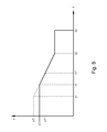
- the Fig. 6 illustrates again in a diagram the course of the proposed method.
- the respective speed of the printed product 21 is plotted on the ordinate of this diagram in association with times on the abscissa.
- the longitudinal folding apparatus 01 is supplied with a first copy of the printed product 21 at a first speed v1, this first speed v1 being determined as a function of z. B. can take different values of the production speed of the printing press or the type of production of the folder.
- This copy of the printed product 21 passes on the folding table 03 at a time t1 with the braking device, z. B.
- the folding blade 06 in a touch contact, while this copy of the printed product 21 in continuation of its preferably translational movement between the folding table 03 and the folding blade 06 in the direction of the transport path of the printed product 21 limiting stationary stopper 22 slides and finally braked against this stop 22 abuts ,
- the contact between the copy of the printed product 21 and the braking device is made as soon as the front edge 33 of the printed product 21 seen in the transport direction T is in a path runs, the length of which is defined by a range of action of the braking device, in particular by the length L06 of the folding blade 06, wherein in the range of action of the braking device of the moving with the first speed printed product 21 decelerating frictional engagement between the printed product 21 and the braking device can be produced.
- the frictional engagement between the copy of the printed product 21 and the folding blade 06 which begins with the contact contact, exists at least as long as the leading edge 33 of the printed product 21 resting on the folding table 03 is below the folding blade 06, wherein the Folding knife 06 and this copy of the printed product 21 touch each other.
- this copy of the printed product 21 by sliding, performs a movement relative to the folding blade 06.
- the stationary stop 22 directed end 34 of the folding blade 06 is arranged by this the transport path of the printed product 21 limiting stop 22 in a predetermined by the construction of the longitudinal folding apparatus 01 fixed distance B ( Fig. 5 ), this distance B z. B. is in the range between 20 mm and 100 mm.
- the measuring path M in which the second speed v2 of the decelerated copy of the printed product 21 is determined, is arranged within the distance B of the end 34 of the folding blade 06 to the stop 22.
- a braked by the braking device copy of the printed product 21 passes through the preferably caused by the folding blade 06 and / or a brush assembly braking at least with its leading edge 33 at the second speed v2 the braking distance downstream measuring section M and then encounters another later time t3 with his Leading edge 33 on the stationary stop 22, whereby this copy of the printed product 21 comes to a standstill with respect to its translational movement on the folding table 03.
- the second speed v2 of the copy of the printed product 21 should have an actual value which corresponds to a specific predetermined desired value within permissible limits.
- This value for the second speed v2 is determined as a function of the impact energy considered permissible, with which a copy of the print product 21 to be folded longitudinally may bounce against the stop 22 which delimits its transport path and is arranged in the longitudinal folder 01, without damage by plastic deformation or to suffer a rift.
- This preferably tolerance-sensitive setpoint value for the second speed v2 is z. B. stored in a memory of the control unit 26.
- a plurality of manually or automatically selectable set values for the second speed v2 of the printed product 21 may be stored, wherein, depending on the grammage used for the production of this printed product 21 Substrate and / or the thickness of this printed product 21 and / or the surface texture characterizing coefficient of friction ⁇ another setpoint is selected or at least selectable.
- the measuring path M of the current actual value of the second speed v2 in a particular production of at least one copy preferably of a sequence of successively produced copies of this printed product 21 is determined.
- the currently determined actual value of the second speed v2 of the copy in question or z. B. an average, which has been determined from the respective actual values of the second speed v2 of belonging to a particular sequence copies of this printed product 21 is compared with the previously selected setpoint for the second speed v2 of the printed product 21. If a deviation outside a tolerable tolerance, i. H. a difference between the actual value or the mean value and the applicable setpoint value is determined, z. B. the control unit 26 via the cam 16 controlled by it z. B. in cooperation with the levers 07; 14 the time t1 new, to which the braking device, for. B.
- the time t1 characterizing the beginning of the frictional engagement is thus variably adjustable with respect to the time t2 at which the actual value of the second speed v2 of the printed product 21 is determined and becomes dependent on a detected deviation of the actual value of the second speed v2 from its set value adjusted as needed.
Landscapes
- Engineering & Computer Science (AREA)
- Mechanical Engineering (AREA)
- Folding Of Thin Sheet-Like Materials, Special Discharging Devices, And Others (AREA)
- Shaping Of Tube Ends By Bending Or Straightening (AREA)
- Processing Of Meat And Fish (AREA)
Applications Claiming Priority (1)
| Application Number | Priority Date | Filing Date | Title |
|---|---|---|---|
| DE102007032911A DE102007032911B4 (de) | 2007-07-14 | 2007-07-14 | Verfahren zum Betrieb eines Längsfalzapparates |
Publications (3)
| Publication Number | Publication Date |
|---|---|
| EP2017210A2 true EP2017210A2 (fr) | 2009-01-21 |
| EP2017210A3 EP2017210A3 (fr) | 2010-08-25 |
| EP2017210B1 EP2017210B1 (fr) | 2011-01-12 |
Family
ID=39855064
Family Applications (1)
| Application Number | Title | Priority Date | Filing Date |
|---|---|---|---|
| EP08153403A Not-in-force EP2017210B1 (fr) | 2007-07-14 | 2008-03-27 | Procédé destiné au fonctionnement d'un appareil de pliage en longueur |
Country Status (3)
| Country | Link |
|---|---|
| EP (1) | EP2017210B1 (fr) |
| AT (1) | ATE495127T1 (fr) |
| DE (2) | DE102007032911B4 (fr) |
Cited By (3)
| Publication number | Priority date | Publication date | Assignee | Title |
|---|---|---|---|---|
| DE102009003235B3 (de) * | 2009-03-27 | 2010-07-08 | Koenig & Bauer Aktiengesellschaft | Verfahren zum Betreiben eines ein Falzmesser und einen Falztisch aufweisenden Längsfalzapparates und ein Längsfalzapparat |
| EP2487127A1 (fr) | 2011-02-10 | 2012-08-15 | Koenig & Bauer Aktiengesellschaft | Procédé de détermination d'une position inclinée d'un pli produit par le pliage longitudinal d'un produit par un appareil de pliage longitudinal ainsi qu'appareil de pliage longitudinal doté de moyens de détermination d'une telle position inclinée |
| CN111056339A (zh) * | 2018-10-17 | 2020-04-24 | 好利用国际株式会社 | 刀式折叠机 |
Citations (6)
| Publication number | Priority date | Publication date | Assignee | Title |
|---|---|---|---|---|
| EP0639523A1 (fr) | 1993-08-17 | 1995-02-22 | Rockwell Graphic Systems Inc. | Appareil de pliage |
| DE19504769A1 (de) | 1995-02-14 | 1996-08-22 | Roland Man Druckmasch | Falzapparat |
| DE19921169C2 (de) | 1999-05-07 | 2003-03-13 | Roland Man Druckmasch | Vorrichtung zum Abbremsen von Papierbögen |
| WO2005095245A1 (fr) | 2004-04-01 | 2005-10-13 | Koenig & Bauer Aktiengesellschaft | Systeme a trajectoires de traitement alternatives pour realiser des post-traitements sur des produits, appareil de pliage longitudinal, et procede permettant le fonctionnement synchrone d'un appareil de pliage |
| DE102005007745A1 (de) | 2005-02-18 | 2006-08-31 | Man Roland Druckmaschinen Ag | Falzapparat für eine Druckmaschine |
| WO2007042391A1 (fr) | 2005-10-13 | 2007-04-19 | Koenig & Bauer Aktiengesellschaft | Appareil de pliage longitudinal, procede pour faire fonctionner un appareil de pliage longitudinal, et procede pour synchroniser un appareil de pliage longitudinal |
-
2007
- 2007-07-14 DE DE102007032911A patent/DE102007032911B4/de not_active Expired - Fee Related
-
2008
- 2008-03-27 DE DE502008002264T patent/DE502008002264D1/de active Active
- 2008-03-27 AT AT08153403T patent/ATE495127T1/de active
- 2008-03-27 EP EP08153403A patent/EP2017210B1/fr not_active Not-in-force
Patent Citations (7)
| Publication number | Priority date | Publication date | Assignee | Title |
|---|---|---|---|---|
| EP0639523A1 (fr) | 1993-08-17 | 1995-02-22 | Rockwell Graphic Systems Inc. | Appareil de pliage |
| DE69400629T2 (de) | 1993-08-17 | 1997-02-13 | Rockwell Graphic Systems Inc | Falzapparat |
| DE19504769A1 (de) | 1995-02-14 | 1996-08-22 | Roland Man Druckmasch | Falzapparat |
| DE19921169C2 (de) | 1999-05-07 | 2003-03-13 | Roland Man Druckmasch | Vorrichtung zum Abbremsen von Papierbögen |
| WO2005095245A1 (fr) | 2004-04-01 | 2005-10-13 | Koenig & Bauer Aktiengesellschaft | Systeme a trajectoires de traitement alternatives pour realiser des post-traitements sur des produits, appareil de pliage longitudinal, et procede permettant le fonctionnement synchrone d'un appareil de pliage |
| DE102005007745A1 (de) | 2005-02-18 | 2006-08-31 | Man Roland Druckmaschinen Ag | Falzapparat für eine Druckmaschine |
| WO2007042391A1 (fr) | 2005-10-13 | 2007-04-19 | Koenig & Bauer Aktiengesellschaft | Appareil de pliage longitudinal, procede pour faire fonctionner un appareil de pliage longitudinal, et procede pour synchroniser un appareil de pliage longitudinal |
Cited By (14)
| Publication number | Priority date | Publication date | Assignee | Title |
|---|---|---|---|---|
| CN102365224B (zh) * | 2009-03-27 | 2014-06-25 | 柯尼格及包尔公开股份有限公司 | 用于校正从纵向折页机的两个折页辊的折页间隙中输出的产品的倾斜位置的方法以及纵向折页机 |
| DE102009003240B4 (de) * | 2009-03-27 | 2021-01-28 | Koenig & Bauer Ag | Verfahren zur Korrektur einer Schräglage eines aus einem Falzwalzenspalt eines Längsfalzapparates austretenden Produktes und Längsfalzapparat |
| DE102009003237A1 (de) | 2009-03-27 | 2010-10-07 | Koenig & Bauer Aktiengesellschaft | Verfahren zur Korrektur einer Schräglage eines Produktes auf einem Falztisch eines Längsfalzapparates und ein Längsfalzapparat |
| DE102009003240A1 (de) | 2009-03-27 | 2010-10-07 | Koenig & Bauer Aktiengesellschaft | Verfahren zur Korrektur einer Schräglage eines aus einem Falzwalzenspalt eines Längsfalzapparates austretenden Produktes und Längsfalzapparat |
| CN102365220A (zh) * | 2009-03-27 | 2012-02-29 | 柯尼格及包尔公开股份有限公司 | 用于运行具有折页刀和折页台的纵向折页机的方法以及纵向折页机 |
| US8323162B2 (en) | 2009-03-27 | 2012-12-04 | Koenig & Bauer Aktiengesellschaft | Method for correcting a skewed position of a product exiting a folding roller gap between two folding rollers of a longitudinal folding apparatus, and a longitudinal folding apparatus |
| CN102365220B (zh) * | 2009-03-27 | 2015-06-03 | 柯尼格及包尔公开股份有限公司 | 用于运行具有折页刀和折页台的纵向折页机的方法以及纵向折页机 |
| DE102009003235B3 (de) * | 2009-03-27 | 2010-07-08 | Koenig & Bauer Aktiengesellschaft | Verfahren zum Betreiben eines ein Falzmesser und einen Falztisch aufweisenden Längsfalzapparates und ein Längsfalzapparat |
| WO2010108559A1 (fr) * | 2009-03-27 | 2010-09-30 | Koenig & Bauer Aktiengesellschaft | Procédé pour faire fonctionner une plieuse longitudinale présentant une lame de pliage et une table de pliage et plieuse longitudinale |
| DE102011003925A1 (de) | 2011-02-10 | 2012-08-16 | Koenig & Bauer Aktiengesellschaft | Verfahren zur Ermittlung einer Schräglage eines durch Längsfalzen eines Produktes durch einen Längsfalzapparat erzeugten Falzbruchs sowie Längsfalzapparat mit Mitteln zur Ermittlung einer derartigen Schräglage |
| DE102011003925B4 (de) * | 2011-02-10 | 2013-12-05 | Koenig & Bauer Aktiengesellschaft | Verfahren zur Ermittlung einer Schräglage eines durch Längsfalzen eines Produktes durch einen Längsfalzapparat erzeugten Falzbruchs sowie Längsfalzapparat mit Mitteln zur Ermittlung einer derartigen Schräglage |
| EP2487127A1 (fr) | 2011-02-10 | 2012-08-15 | Koenig & Bauer Aktiengesellschaft | Procédé de détermination d'une position inclinée d'un pli produit par le pliage longitudinal d'un produit par un appareil de pliage longitudinal ainsi qu'appareil de pliage longitudinal doté de moyens de détermination d'une telle position inclinée |
| CN111056339A (zh) * | 2018-10-17 | 2020-04-24 | 好利用国际株式会社 | 刀式折叠机 |
| CN111056339B (zh) * | 2018-10-17 | 2023-06-30 | 好利用国际株式会社 | 刀式折叠机 |
Also Published As
| Publication number | Publication date |
|---|---|
| EP2017210A3 (fr) | 2010-08-25 |
| DE102007032911A1 (de) | 2009-01-15 |
| ATE495127T1 (de) | 2011-01-15 |
| DE102007032911B4 (de) | 2010-02-04 |
| DE502008002264D1 (de) | 2011-02-24 |
| EP2017210B1 (fr) | 2011-01-12 |
Similar Documents
| Publication | Publication Date | Title |
|---|---|---|
| DE3844897C2 (de) | Verzögerungs-Vorrichtung für Bogenlagen | |
| DE202012100708U1 (de) | Stanzvorrichtung mit kontinuierlich laufender Stanzwalze | |
| EP1603818B1 (fr) | Procede et dispositif pour traiter une bande en papier ou en matiere pour film | |
| EP3533609B1 (fr) | Dispositif et procédé de traitement ultérieur séquentiel de feuilles imprimées | |
| EP2017210B1 (fr) | Procédé destiné au fonctionnement d'un appareil de pliage en longueur | |
| EP2132117B1 (fr) | Procédé et circuit de commande permettant de régler un interstice | |
| CH713149A1 (de) | Verfahren und Vorrichtung zum Transport dickenvariabler Druckprodukte. | |
| DE3812685C2 (de) | Verzögerungs-Vorrichtung für Bogenlagen | |
| EP1934124B1 (fr) | Procede pour synchroniser un appareil de pliage longitudinal | |
| EP1840061A1 (fr) | Elément de guidage de feuille et de conduite de feuille actif | |
| EP1730063B1 (fr) | Systeme a trajectoires de traitement alternatives pour realiser des post-traitements sur des produits, appareil de pliage longitudinal, et procede permettant le fonctionnement synchrone d'un appareil de pliage | |
| EP1720786B1 (fr) | Appareil de pliage longitudinal pourvu d'une longueur de freinage | |
| EP0464530A2 (fr) | Dispositif pour faire chevaucher et déposer des feuilles coupées dans une bande de matériel par un coupeur en travers | |
| EP1972587A1 (fr) | Dispositif destiné à collecter des produits imprimés sur un cylindre de collecte | |
| CH712159A2 (de) | Verfahren und Vorrichtung für den Transport von dickenvariablen Druckprodukten. | |
| EP1732833B1 (fr) | Procede et dispositifs pour couper et/ou acheminer une bande dans une phase de traitement ulterieur | |
| DE102008042902B4 (de) | Bogenbremse einer Druckmaschine und Verfahren zum Antrieb einer Bogenbremse | |
| EP2065212A2 (fr) | Dispositif destiné à la transmission d'un dos de livre d'un dispositif de roulage vers un poste de transfert | |
| EP2487127A1 (fr) | Procédé de détermination d'une position inclinée d'un pli produit par le pliage longitudinal d'un produit par un appareil de pliage longitudinal ainsi qu'appareil de pliage longitudinal doté de moyens de détermination d'une telle position inclinée | |
| EP1044154B1 (fr) | Dispositif pour transformer une pile d'objets recouvrants en une formation a recouvrement | |
| DE102004053536A1 (de) | Verfahren und Vorrichtung zum Kappen und/oder Zuführen eines Stranges in eine Weiterverarbeitungsstufe sowie Strangverarbeitungssystem | |
| DE102004009863B4 (de) | Verfahren in einem Längsfalzapparat | |
| WO2015062583A2 (fr) | Module de pliage de feuilles de papier, dispositif de pliage comportant le module de pliage et procédé de pliage de feuilles de papier | |
| WO1998017563A2 (fr) | Procede et dispositifs pour introduire un materiau sous forme de feuille dans une imprimante ou une photocopieuse | |
| EP0463343A2 (fr) | Machine d'impression |
Legal Events
| Date | Code | Title | Description |
|---|---|---|---|
| PUAI | Public reference made under article 153(3) epc to a published international application that has entered the european phase |
Free format text: ORIGINAL CODE: 0009012 |
|
| AK | Designated contracting states |
Kind code of ref document: A2 Designated state(s): AT BE BG CH CY CZ DE DK EE ES FI FR GB GR HR HU IE IS IT LI LT LU LV MC MT NL NO PL PT RO SE SI SK TR |
|
| AX | Request for extension of the european patent |
Extension state: AL BA MK RS |
|
| PUAL | Search report despatched |
Free format text: ORIGINAL CODE: 0009013 |
|
| AK | Designated contracting states |
Kind code of ref document: A3 Designated state(s): AT BE BG CH CY CZ DE DK EE ES FI FR GB GR HR HU IE IS IT LI LT LU LV MC MT NL NO PL PT RO SE SI SK TR |
|
| AX | Request for extension of the european patent |
Extension state: AL BA MK RS |
|
| RIC1 | Information provided on ipc code assigned before grant |
Ipc: B65H 45/18 20060101AFI20081024BHEP Ipc: B65H 29/68 20060101ALI20100722BHEP Ipc: B65H 9/00 20060101ALI20100722BHEP Ipc: B65H 9/14 20060101ALI20100722BHEP |
|
| 17P | Request for examination filed |
Effective date: 20100804 |
|
| GRAP | Despatch of communication of intention to grant a patent |
Free format text: ORIGINAL CODE: EPIDOSNIGR1 |
|
| RIC1 | Information provided on ipc code assigned before grant |
Ipc: B65H 29/68 20060101ALI20100902BHEP Ipc: B65H 45/18 20060101AFI20100902BHEP Ipc: B65H 9/14 20060101ALI20100902BHEP Ipc: B65H 9/00 20060101ALI20100902BHEP |
|
| GRAS | Grant fee paid |
Free format text: ORIGINAL CODE: EPIDOSNIGR3 |
|
| GRAA | (expected) grant |
Free format text: ORIGINAL CODE: 0009210 |
|
| AK | Designated contracting states |
Kind code of ref document: B1 Designated state(s): AT BE BG CH CY CZ DE DK EE ES FI FR GB GR HR HU IE IS IT LI LT LU LV MC MT NL NO PL PT RO SE SI SK TR |
|
| REG | Reference to a national code |
Ref country code: GB Ref legal event code: FG4D Free format text: NOT ENGLISH |
|
| REG | Reference to a national code |
Ref country code: CH Ref legal event code: EP |
|
| REG | Reference to a national code |
Ref country code: IE Ref legal event code: FG4D Free format text: LANGUAGE OF EP DOCUMENT: GERMAN |
|
| REF | Corresponds to: |
Ref document number: 502008002264 Country of ref document: DE Date of ref document: 20110224 Kind code of ref document: P |
|
| REG | Reference to a national code |
Ref country code: DE Ref legal event code: R096 Ref document number: 502008002264 Country of ref document: DE Effective date: 20110224 |
|
| AKX | Designation fees paid |
Designated state(s): AT BE BG CH CY CZ DE DK EE ES FI FR GB GR HR HU IE IS IT LI LT LU LV MC MT NL NO PL PT RO SE SI SK TR |
|
| REG | Reference to a national code |
Ref country code: NL Ref legal event code: VDEP Effective date: 20110112 |
|
| LTIE | Lt: invalidation of european patent or patent extension |
Effective date: 20110112 |
|
| PG25 | Lapsed in a contracting state [announced via postgrant information from national office to epo] |
Ref country code: NO Free format text: LAPSE BECAUSE OF FAILURE TO SUBMIT A TRANSLATION OF THE DESCRIPTION OR TO PAY THE FEE WITHIN THE PRESCRIBED TIME-LIMIT Effective date: 20110412 Ref country code: LV Free format text: LAPSE BECAUSE OF FAILURE TO SUBMIT A TRANSLATION OF THE DESCRIPTION OR TO PAY THE FEE WITHIN THE PRESCRIBED TIME-LIMIT Effective date: 20110112 Ref country code: PT Free format text: LAPSE BECAUSE OF FAILURE TO SUBMIT A TRANSLATION OF THE DESCRIPTION OR TO PAY THE FEE WITHIN THE PRESCRIBED TIME-LIMIT Effective date: 20110512 Ref country code: IS Free format text: LAPSE BECAUSE OF FAILURE TO SUBMIT A TRANSLATION OF THE DESCRIPTION OR TO PAY THE FEE WITHIN THE PRESCRIBED TIME-LIMIT Effective date: 20110512 Ref country code: SE Free format text: LAPSE BECAUSE OF FAILURE TO SUBMIT A TRANSLATION OF THE DESCRIPTION OR TO PAY THE FEE WITHIN THE PRESCRIBED TIME-LIMIT Effective date: 20110112 Ref country code: GR Free format text: LAPSE BECAUSE OF FAILURE TO SUBMIT A TRANSLATION OF THE DESCRIPTION OR TO PAY THE FEE WITHIN THE PRESCRIBED TIME-LIMIT Effective date: 20110413 Ref country code: LT Free format text: LAPSE BECAUSE OF FAILURE TO SUBMIT A TRANSLATION OF THE DESCRIPTION OR TO PAY THE FEE WITHIN THE PRESCRIBED TIME-LIMIT Effective date: 20110112 Ref country code: ES Free format text: LAPSE BECAUSE OF FAILURE TO SUBMIT A TRANSLATION OF THE DESCRIPTION OR TO PAY THE FEE WITHIN THE PRESCRIBED TIME-LIMIT Effective date: 20110423 Ref country code: HR Free format text: LAPSE BECAUSE OF FAILURE TO SUBMIT A TRANSLATION OF THE DESCRIPTION OR TO PAY THE FEE WITHIN THE PRESCRIBED TIME-LIMIT Effective date: 20110112 |
|
| REG | Reference to a national code |
Ref country code: IE Ref legal event code: FD4D |
|
| PG25 | Lapsed in a contracting state [announced via postgrant information from national office to epo] |
Ref country code: BG Free format text: LAPSE BECAUSE OF FAILURE TO SUBMIT A TRANSLATION OF THE DESCRIPTION OR TO PAY THE FEE WITHIN THE PRESCRIBED TIME-LIMIT Effective date: 20110412 Ref country code: NL Free format text: LAPSE BECAUSE OF FAILURE TO SUBMIT A TRANSLATION OF THE DESCRIPTION OR TO PAY THE FEE WITHIN THE PRESCRIBED TIME-LIMIT Effective date: 20110112 Ref country code: SI Free format text: LAPSE BECAUSE OF FAILURE TO SUBMIT A TRANSLATION OF THE DESCRIPTION OR TO PAY THE FEE WITHIN THE PRESCRIBED TIME-LIMIT Effective date: 20110112 Ref country code: FI Free format text: LAPSE BECAUSE OF FAILURE TO SUBMIT A TRANSLATION OF THE DESCRIPTION OR TO PAY THE FEE WITHIN THE PRESCRIBED TIME-LIMIT Effective date: 20110112 Ref country code: PL Free format text: LAPSE BECAUSE OF FAILURE TO SUBMIT A TRANSLATION OF THE DESCRIPTION OR TO PAY THE FEE WITHIN THE PRESCRIBED TIME-LIMIT Effective date: 20110112 Ref country code: CY Free format text: LAPSE BECAUSE OF FAILURE TO SUBMIT A TRANSLATION OF THE DESCRIPTION OR TO PAY THE FEE WITHIN THE PRESCRIBED TIME-LIMIT Effective date: 20110112 |
|
| BERE | Be: lapsed |
Owner name: KOENIG & BAUER A.G. Effective date: 20110331 |
|
| PG25 | Lapsed in a contracting state [announced via postgrant information from national office to epo] |
Ref country code: EE Free format text: LAPSE BECAUSE OF FAILURE TO SUBMIT A TRANSLATION OF THE DESCRIPTION OR TO PAY THE FEE WITHIN THE PRESCRIBED TIME-LIMIT Effective date: 20110112 Ref country code: IE Free format text: LAPSE BECAUSE OF FAILURE TO SUBMIT A TRANSLATION OF THE DESCRIPTION OR TO PAY THE FEE WITHIN THE PRESCRIBED TIME-LIMIT Effective date: 20110112 Ref country code: MC Free format text: LAPSE BECAUSE OF NON-PAYMENT OF DUE FEES Effective date: 20110331 Ref country code: DK Free format text: LAPSE BECAUSE OF FAILURE TO SUBMIT A TRANSLATION OF THE DESCRIPTION OR TO PAY THE FEE WITHIN THE PRESCRIBED TIME-LIMIT Effective date: 20110112 |
|
| PLBE | No opposition filed within time limit |
Free format text: ORIGINAL CODE: 0009261 |
|
| STAA | Information on the status of an ep patent application or granted ep patent |
Free format text: STATUS: NO OPPOSITION FILED WITHIN TIME LIMIT |
|
| PG25 | Lapsed in a contracting state [announced via postgrant information from national office to epo] |
Ref country code: SK Free format text: LAPSE BECAUSE OF FAILURE TO SUBMIT A TRANSLATION OF THE DESCRIPTION OR TO PAY THE FEE WITHIN THE PRESCRIBED TIME-LIMIT Effective date: 20110112 Ref country code: RO Free format text: LAPSE BECAUSE OF FAILURE TO SUBMIT A TRANSLATION OF THE DESCRIPTION OR TO PAY THE FEE WITHIN THE PRESCRIBED TIME-LIMIT Effective date: 20110112 Ref country code: CZ Free format text: LAPSE BECAUSE OF FAILURE TO SUBMIT A TRANSLATION OF THE DESCRIPTION OR TO PAY THE FEE WITHIN THE PRESCRIBED TIME-LIMIT Effective date: 20110112 |
|
| 26N | No opposition filed |
Effective date: 20111013 |
|
| PG25 | Lapsed in a contracting state [announced via postgrant information from national office to epo] |
Ref country code: BE Free format text: LAPSE BECAUSE OF NON-PAYMENT OF DUE FEES Effective date: 20110331 Ref country code: MT Free format text: LAPSE BECAUSE OF FAILURE TO SUBMIT A TRANSLATION OF THE DESCRIPTION OR TO PAY THE FEE WITHIN THE PRESCRIBED TIME-LIMIT Effective date: 20110112 |
|
| REG | Reference to a national code |
Ref country code: DE Ref legal event code: R097 Ref document number: 502008002264 Country of ref document: DE Effective date: 20111013 |
|
| PGFP | Annual fee paid to national office [announced via postgrant information from national office to epo] |
Ref country code: FR Payment date: 20120405 Year of fee payment: 5 |
|
| PGFP | Annual fee paid to national office [announced via postgrant information from national office to epo] |
Ref country code: IT Payment date: 20120322 Year of fee payment: 5 Ref country code: GB Payment date: 20120327 Year of fee payment: 5 |
|
| REG | Reference to a national code |
Ref country code: CH Ref legal event code: PL |
|
| PG25 | Lapsed in a contracting state [announced via postgrant information from national office to epo] |
Ref country code: CH Free format text: LAPSE BECAUSE OF NON-PAYMENT OF DUE FEES Effective date: 20120331 Ref country code: LI Free format text: LAPSE BECAUSE OF NON-PAYMENT OF DUE FEES Effective date: 20120331 |
|
| PG25 | Lapsed in a contracting state [announced via postgrant information from national office to epo] |
Ref country code: LU Free format text: LAPSE BECAUSE OF NON-PAYMENT OF DUE FEES Effective date: 20110327 |
|
| PG25 | Lapsed in a contracting state [announced via postgrant information from national office to epo] |
Ref country code: TR Free format text: LAPSE BECAUSE OF FAILURE TO SUBMIT A TRANSLATION OF THE DESCRIPTION OR TO PAY THE FEE WITHIN THE PRESCRIBED TIME-LIMIT Effective date: 20110112 |
|
| PG25 | Lapsed in a contracting state [announced via postgrant information from national office to epo] |
Ref country code: HU Free format text: LAPSE BECAUSE OF FAILURE TO SUBMIT A TRANSLATION OF THE DESCRIPTION OR TO PAY THE FEE WITHIN THE PRESCRIBED TIME-LIMIT Effective date: 20110112 |
|
| GBPC | Gb: european patent ceased through non-payment of renewal fee |
Effective date: 20130327 |
|
| REG | Reference to a national code |
Ref country code: FR Ref legal event code: ST Effective date: 20131129 |
|
| PG25 | Lapsed in a contracting state [announced via postgrant information from national office to epo] |
Ref country code: FR Free format text: LAPSE BECAUSE OF NON-PAYMENT OF DUE FEES Effective date: 20130402 Ref country code: GB Free format text: LAPSE BECAUSE OF NON-PAYMENT OF DUE FEES Effective date: 20130327 |
|
| PG25 | Lapsed in a contracting state [announced via postgrant information from national office to epo] |
Ref country code: IT Free format text: LAPSE BECAUSE OF NON-PAYMENT OF DUE FEES Effective date: 20130327 |
|
| REG | Reference to a national code |
Ref country code: AT Ref legal event code: MM01 Ref document number: 495127 Country of ref document: AT Kind code of ref document: T Effective date: 20130327 |
|
| PG25 | Lapsed in a contracting state [announced via postgrant information from national office to epo] |
Ref country code: AT Free format text: LAPSE BECAUSE OF NON-PAYMENT OF DUE FEES Effective date: 20130327 |
|
| PGFP | Annual fee paid to national office [announced via postgrant information from national office to epo] |
Ref country code: DE Payment date: 20150318 Year of fee payment: 8 |
|
| REG | Reference to a national code |
Ref country code: DE Ref legal event code: R081 Ref document number: 502008002264 Country of ref document: DE Owner name: KOENIG & BAUER AG, DE Free format text: FORMER OWNER: KOENIG & BAUER AKTIENGESELLSCHAFT, 97080 WUERZBURG, DE |
|
| REG | Reference to a national code |
Ref country code: DE Ref legal event code: R119 Ref document number: 502008002264 Country of ref document: DE |
|
| PG25 | Lapsed in a contracting state [announced via postgrant information from national office to epo] |
Ref country code: DE Free format text: LAPSE BECAUSE OF NON-PAYMENT OF DUE FEES Effective date: 20161001 |