EP2018334B1 - Sauggreifer - Google Patents
Sauggreifer Download PDFInfo
- Publication number
- EP2018334B1 EP2018334B1 EP07711234A EP07711234A EP2018334B1 EP 2018334 B1 EP2018334 B1 EP 2018334B1 EP 07711234 A EP07711234 A EP 07711234A EP 07711234 A EP07711234 A EP 07711234A EP 2018334 B1 EP2018334 B1 EP 2018334B1
- Authority
- EP
- European Patent Office
- Prior art keywords
- suction
- needle
- suction gripper
- insert
- needle insert
- Prior art date
- Legal status (The legal status is an assumption and is not a legal conclusion. Google has not performed a legal analysis and makes no representation as to the accuracy of the status listed.)
- Not-in-force
Links
Images


Classifications
-
- B—PERFORMING OPERATIONS; TRANSPORTING
- B65—CONVEYING; PACKING; STORING; HANDLING THIN OR FILAMENTARY MATERIAL
- B65G—TRANSPORT OR STORAGE DEVICES, e.g. CONVEYORS FOR LOADING OR TIPPING, SHOP CONVEYOR SYSTEMS OR PNEUMATIC TUBE CONVEYORS
- B65G47/00—Article or material-handling devices associated with conveyors; Methods employing such devices
- B65G47/74—Feeding, transfer, or discharging devices of particular kinds or types
- B65G47/90—Devices for picking-up and depositing articles or materials
- B65G47/91—Devices for picking-up and depositing articles or materials incorporating pneumatic, e.g. suction, grippers
-
- B—PERFORMING OPERATIONS; TRANSPORTING
- B65—CONVEYING; PACKING; STORING; HANDLING THIN OR FILAMENTARY MATERIAL
- B65G—TRANSPORT OR STORAGE DEVICES, e.g. CONVEYORS FOR LOADING OR TIPPING, SHOP CONVEYOR SYSTEMS OR PNEUMATIC TUBE CONVEYORS
- B65G47/00—Article or material-handling devices associated with conveyors; Methods employing such devices
- B65G47/74—Feeding, transfer, or discharging devices of particular kinds or types
- B65G47/90—Devices for picking-up and depositing articles or materials
Definitions
- the present invention relates to a suction gripper according to the preamble of claim 1, as it is known from EP 0 845 434 A1 is known.
- an elongated suction cup with a bellows which additionally has a needle for gripping an object.
- the invention is based on the prior art, the object to provide a suction pad with which a lifting of packages is possible even with front-side suction.
- a suction gripper in which at least one needle is provided for gripping an object and the needle is arranged on a needle insert, characterized in that the needle insert is mounted in a suction port, wherein the needle insert a fastening sleeve for attachment in the Suction port and a arranged at the front longitudinal end of the mounting sleeve and extending at a right angle thereto extending needle plate, wherein the bore of the mounting sleeve is in communication with the front of the needle insert through a connection opening in the needle insert.
- the needle insert is replaceable.
- the number of needles and / or their length and / or their surface density can be varied depending on the application.
- the needle insert can be retrofitted, i. Can be retrofitted even with existing suction pads.
- the needle insert can be screwed.
- the needle insert can also be clamped.
- the needle insert is mounted in a suction opening.
- the needle insert must be mountable therein to still provide suction with the suction pad.
- At least one exposed ventilation slot is provided which extends from the edge of the opening in the needle plate on the one hand in the outward direction and on the other hand in the fastening sleeve in the direction of the rear longitudinal end of the fastening sleeve.
- the suction pad is a Faltenbalgsauggreifer.
- the suction opening can be arranged centrally.
- suction gripper is a surface suction.
- Suction mats are intended to mean suction mats, such as those supplied by the company Unigripper, for example.
- the invention is based on the surprising finding that by combining a suction gripper with at least one needle, the physical action principle of suction pads, namely by holding by adhesion, combined with the physical action principle of Nadelgreifern, namely holding by positive engagement, and thereby the Kraftautbringung to a package thus, it is extended in three directions without appreciably damaging it.
- front refers to the suction side or the side facing an object to be gripped.
- the suction gripper 10 is a bellows-type suction gripper with a bellows-type body 12 made of elastic plastic with a circumferential front sealing lip 14 and a central rear suction opening 16, which is connectable to a vacuum source (not shown).
- a vacuum source not shown
- an internal thread 18 is provided into which the external thread 20 of the fastening sleeve 22 of a needle insert 24 is screwed.
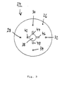
- the needle insert 24 has a needle plate 26 arranged on the front end of the fastening sleeve 22 and extending at right angles thereto, arranged centrally on the needle plate 26 circular in shape and has circumferentially laterally spaced from the body 12 and four on the same radius by 90 ° spaced needles 28, 30, 32 and 34.
- the needles 28, 30, 32, and 34 extend forward, ie to an object to be gripped, and have a length in the range of two to three millimeters.
- the bore 36 of the mounting sleeve 22 is connected via a circular connection opening 38 with the front of the Faltenbalgsauggreifers in combination.
- the needles 28, 30, 32 and 34 are held by the negative pressure of Faltenbalgsauggreifers in direct contact with the package surface, because the package surface is virtually drawn to the needles, and not pressed as in conventional needle grippers the needles until penetration against the package , no deformation of the package takes place. Furthermore, the very small length of the needles and the stop by the needle plate, which prevents puncture, lead to minimal damage to the package. It only results in a superficial damage in the form of a dotted pattern. The number and arrangement of the needles and the tight fit allow considerable force application in all lateral directions and prevent tearing of the holes under load.
Landscapes
- Engineering & Computer Science (AREA)
- Mechanical Engineering (AREA)
- Manipulator (AREA)
- Advancing Webs (AREA)
- Scissors And Nippers (AREA)
Description
- Die vorliegende Erfindung betrifft einen Sauggreifer gemäss dem Oberbegriff des Anspruchs 1, wie er aus der
EP 0 845 434 A1 bekannt ist. - Beim Entladen zum Beispiel eines deckenhoch beladenen Containers ist man häufig mit einer geschlossenen Paketwand konfrontiert. In einem derartigen Fall ist von allen Paketen nur die Vorderseite zu sehen. Dies weist den Nachteil auf, daß ein zu greifendes Paket nur eine Angriffsfläche bietet und wenig Bewegungsfreiraum existiert. Da sich aufgrund des Beladens und/oder beim Transport die unter dem zu greifenden Paket befindlichen Pakete häufig verformen und/oder eindrücken, liegt das zu greifende Paket oft in einer Art Mulde und wird es durch teilweise nicht unerhebliche Klemmkräfte in seiner Position gehalten. Demzufolge müssen an dem Paket Kräfte in zwei Richtungen aufgebracht werden. Zum einen Kräfte nach oben, um es aus der Mulde zu heben, und zum anderen senkrecht vom Paketstapel, um es aus diesem herauszuziehen. Das Anheben ist hierbei notwendig, da sich sonst beim Herausziehen das untere Paket mitbewegen würde oder im Extremfall der gesamte Paketstapel kippen würde.
- Bei der Kraftaufbringung senkrecht zum Paket wurden bisher sehr gute Ergebnisse mit Sauggreifern, wie zum Beispiel Faltenbalgsauggreifem erreicht, wobei diese allerdings den Nachteil aufweisen, bei seitlichen Kraftverläufen abzureißen, was ein Anheben von Paketen bei stirnseitigem Saugen bisher unmöglich machte.
- Aus der Europäischen Patentanmeldung
EP 0 845 434 A1 ist beispielsweise ein länglicher Saugnapf mit einem Faltenbalg bekannt, der zusätzlich eine Nadel zum Greifen eines Gegenstands aufweist. - Der Erfindung liegt ausgehend vom Stand der Technik die Aufgabe zugrunde, einen Sauggreifer bereitzustellen, mit dem ein Anheben von Paketen auch bei stirnseitigem Saugen möglich ist.
- Erfindungsgemäß wird diese Aufgabe gelöst durch einen Sauggreifer, bei dem mindestens eine Nadel zum Greifen eines Gegenstands vorgesehen ist und die Nadel auf einem Nadeleinsatz angeordnet ist, dadurch gekennzeichnet, daß der Nadeleinsatz in einer Ansaugöffnung montiert ist, wobei der Nadeleinsatz eine Befestigungshülse zur Befestigung in der Ansaugöffnung und eine an dem vorderen Längsende der Befestigungshülse angeordnete und sich in einem rechten Winkel dazu erstreckende Nadelplatte umfasst, wobei die Bohrung der Befestigungshülse mit der Vorderseite des Nadeleinsatzes durch eine Verbindungsöffnung in dem Nadeleinsatz in Verbindung steht.
- Durch geeignete Wahl der Anzahl von Nadeln, deren Länge und Flächendichte können geeignete Greifkräfte an einem Paket ausgeübt werden. Selbstverständlich können auch mehrere Nadeln auf dem Nadeleinsatz angeordnet sein.
- Günstigerweise ist der Nadeleinsatz auswechselbar. Dadurch kann zum Beispiel die Anzahl der Nadeln und/oder deren Länge und/oder deren Flächendichte in Abhängigkeit von dem Anwendungsfall variiert werden.
- Vorteilhafterweise ist der Nadeleinsatz nachrüstbar, d.h. auch bei bereits vorhandenen Sauggreifern nachträglich montierbar.
- Gemäß einer weiteren besonderen Ausführungsform der Erfindung kann vorgesehen sein, dass der Nadeleinsatz einschraubbar ist.
- Alternativ kann der Nadeleinsatz auch klemmbar sein.
- Erfindungsgemäß ist der Nadeleinsatz in einer Ansaugöffnung montiert. Wenn es sich um die einzige Ansaugöffnung des Sauggreifers handelt, so muss natürlich der Nadeleinsatz darin so montierbar sein, dass immer noch eine Ansaugwirkung mit dem Sauggreifer erzielt wird.
- Zweckmäßigerweise ist mindestens ein freiliegender Lüftungsschlitz vorgesehen, der sich von dem Rand der Öffnung einerseits in der Nadelplatte in Richtung nach außen und andererseits in der Befestigungshülse in Richtung auf das hintere Längsende der Befestigungshülse erstreckt. Dadurch erhält man einen optimalen Vakuumaufbau. Es wird auch ein Festsaugen des Nadeleinsatzes selbst vermieden. Auch Etiketten oder ähnliches von Paketen können die Ansaugöffnung so nicht verstopfen, da sie hinter der Nadelplatte liegt.
- Gemäß einer weiteren besonderen Ausführungsform der Erfindung kann vorgesehen sein, dass der Sauggreifer ein Faltenbalgsauggreifer ist.
- Insbesondere kann dabei die Ansaugöffnung mittig angeordnet sein.
- Schließlich ist alternativ denkbar, dass der Sauggreifer ein Flächensauggreifer ist. Mit Flächensauggreifern sollen Saugmatten gemeint sein, wie sie beispielsweise von der Firma Unigripper geliefert werden.
- Der Erfindung liegt die überraschende Erkenntnis zugrunde, daß durch die Kombination eines Sauggreifers mit mindestens einer Nadel das physikalische Wirkprinzip von Sauggreifern, nämlich durch Halten durch Kraftschluß, mit dem physikalischen Wirkprinzip von Nadelgreifern, nämlich Halten durch Formschluß, kombiniert und dadurch die Kraftautbringung an einem Paket somit auf drei Richtungen erweitert wird, ohne es in nennenswerter Weise zu beschädigen.
- Weitere Merkmale und Vorteile der Erfindung ergeben sich aus den Ansprüchen und der nachstehenden Beschreibung, in der ein Ausführungsbeispiel anhand der schematischen Zeichnungen im einzelnen erläutert wird, in denen:
- Figur 1
- eine Draufsicht auf einen Sauggreifer gemäß einer besonderen Ausführungsform der Erfindung von unten zeigt;
- Figur 2
- eine Schnittansicht entlang der Linie II-II von
Figur 1 zeigt; - Figur 3
- eine Einzeldarstellung des Nadeleinsatzes des Sauggreifers von
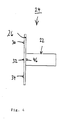
Figur 1 in Draufsicht von unten zeigt; - Figur 4
- eine Seitenansicht des Nadeleinsatzes von
Figur 3 zeigt; und - Figur 5
- eine perspektivische Ansicht des Nadeleinsatzes von
Figur 4 von hinten zeigt. - In der nachfolgenden Beschreibung bezieht sich die Angabe "vordere" auf die Ansaugseite bzw. die zu einem zu greifenden Gegenstand gerichtete Seite.
- Wie sich aus den
Figuren 1 und2 ergibt, handelt es sich bei dem Sauggreifer 10 um einen Faltenbalgsauggreifer mit einem faltenbalgartigen Körper 12 aus elastischem Kunststoff mit einer umlaufenden vorderen Dichtlippe 14 und einer mittigen hinteren Ansaugöffnung 16, die mit einer Unterdruckquelle (nicht gezeigt) verbindbar ist. In dem vorderen Ende der Ansaugöffnung 16 ist ein Innengewinde 18 vorgesehen, in das das Außengewinde 20 der Befestigungshülse 22 eines Nadeleinsatzes 24 geschraubt ist. Der Nadeleinsatz 24 weist eine an dem vorderen Ende der Befestigungshülse 22 angeordnete und sich dazu im rechten Winkel erstreckende, darauf mittig angeordnete Nadelplatte 26 auf Die Nadelplatte 26 ist kreisrund gestaltet und weist seitlich umlaufend einen Abstand zum Körper 12 sowie vier auf demselben Radius um 90 ° beabstandete Nadeln 28, 30, 32 und 34 auf. Die Nadeln 28, 30, 32, und 34 erstrecken sich nach vorne, d. h. zu einem zu greifenden Gegenstand und weisen eine Länge im Bereich von zwei bis drei Millimetern auf. Zur Aufrechterhaltung der Ansaugfunktion des Faltenbalgsauggreifers steht die Bohrung 36 der Befestigungshülse 22 über eine kreisrunde Verbindungsöffnung 38 mit der Vorderseite des Faltenbalgsauggreifers in Verbindung. Darüber hinaus erstrecken sich an den jeweiligen Winkelpositionen der Nadeln 28, 30, 32 und 34 jeweilige freiliegende Lüftungsschlitze 40, 42, 44 bzw. 46 von dem Rand der Verbindungsöffnung 38 einerseits über eine gewisse Strecke in der Nadelplatte 26 radial nach außen und andererseits in der Befestigungshülse 22 über eine gewisse Strecke in Richtung auf das hintere Längsende der Befestigungshülse 22. Dadurch erhält man einen guten Vakuumaufbau. Hierzu kann zusätzlich ein vertikaler Abstand (nicht gezeigt) zwischen der Nadelplatte 26 und dem Körper 12 vorgesehen sein. Alternativ könnten auch Verbindungskanäle in dem Körper 12 zur Herstellung einer Ansaugverbindung mit den Schlitzen 46 und 48 an der Rückseite der Nadelplatte 26 vorgesehen sein. - Dadurch daß die Nadeln 28, 30, 32 und 34 durch den Unterdruck des Faltenbalgsauggreifers in unmittelbarem Kontakt zur Paketoberfläche gehalten werden, weil die Paketoberfläche quasi an die Nadeln gezogen wird, und nicht wie bei herkömmlichen Nadelgreifem die Nadeln bis zum Eindringen gegen das Paket gedrückt werden, findet keine Verformung des Pakets statt. Des weiteren führen die sehr geringe Länge der Nadeln und der Anschlag durch die Nadelplatte, der ein Durchstoßen verhindert, zu einer minimalen Beschädigung des Pakets. Es ergibt sich lediglich eine oberflächliche Beschädigung in Form eines gepunkteten Musters. Die Anzahl und Anordnung der Nadeln sowie der dichte Formschluß ermöglichen eine erhebliche Kraftaufbringung in alle seitlichen Richtungen und verhindern ein Aufreißen der Löcher bei Belastung.
- Die in der vorstehenden Beschreibung, in den Zeichnungen sowie in den Ansprüchen offenbarten Merkmale der Erfindung können sowohl einzeln als auch in beliebigen Kombinationen für die Verwirklichung der Erfindung in ihren verschiedenen Ausführungsformen wesentlich sein.
Claims (9)
- Sauggreifer (10), bei dem mindestens eine Nadel (28;30;32;34) zum Greifen eines Gegenstands vorgesehen ist und die Nadel (28; 30; 32; 34) auf einem Nadeleinsatz (24) angeordnet ist,
dadurch gekennzeichnet,
daß der Nadeleinsatz (24) in einer Ansaugöffnung (16) montiert ist, wobei der Nadeleinsatz (24) eine Befestigungshülse (22) zur Befestigung in der Ansaugöffnung (16) und eine an dem vorderen Längsende der Befestigungshülse (22) angeordnete und sich in einem rechten Winkel dazu erstreckende Nadelplatte (26) umfasst, wobei die Bohrung (36) der Befestigungshülse (22) mit der Vorderseite des Nadeleinsatzes (24) durch eine Verbindungsöffnung (38) in dem Nadeleinsatz (24) in Verbindung steht. - Sauggreifer (10) nach Anspruch 1,
dadurch gekennzeichnet,
daß der Nadeleinsatz (24) auswechselbar ist. - Sauggreifer (10) nach einem der Ansprüche 1 und 2,
dadurch gekennzeichnet,
daß der Nadeleinsatz (24) nachrüstbar ist. - Sauggreifer (10) nach einem der Ansprüche 1 bis 3,
dadurch gekennzeichnet,
daß der Nadeleinsatz (24) einschraubbar ist. - Sauggreifer (10) nach einem der Ansprüche 1 bis 3,
dadurch gekennzeichnet,
daß der Nadeleinsatz (24) klemmbar ist. - Sauggreifer (10) nach einem der Ansprüche 1 bis 5,
dadurch gekennzeichnet,
daß mindestens ein freiliegender Lüftungsschlitz (40, 42, 44, 46) vorgesehen ist, der sich von dem Rand der Öffnung einerseits in der Nadelplatte (26) in Richtung nach außen und andererseits in der Befestigungshülse (22) in Richtung auf das hintere Längsende der Befestigungshülse (22) erstreckt. - Sauggreifer (10) nach einem der vorangehenden Ansprüche,
dadurch gekennzeichnet,
daß er ein Faltenbalgsauggreifer ist. - Sauggreifer (10) nach Anspruch 7,
dadurch gekennzeichnet,
daß die Ansaugöffnung (16) mittig angeordnet ist. - Sauggreifer (10) nach einem der Ansprüche 1 bis 6,
dadurch gekennzeichnet,
daß er ein Flächensauggreifer ist.
Applications Claiming Priority (2)
| Application Number | Priority Date | Filing Date | Title |
|---|---|---|---|
| DE102006022277A DE102006022277B4 (de) | 2006-05-11 | 2006-05-11 | Sauggreifer |
| PCT/DE2007/000480 WO2007131463A1 (de) | 2006-05-11 | 2007-03-16 | Sauggreifer |
Publications (3)
| Publication Number | Publication Date |
|---|---|
| EP2018334A1 EP2018334A1 (de) | 2009-01-28 |
| EP2018334B1 true EP2018334B1 (de) | 2011-06-22 |
| EP2018334B8 EP2018334B8 (de) | 2011-09-21 |
Family
ID=38171358
Family Applications (1)
| Application Number | Title | Priority Date | Filing Date |
|---|---|---|---|
| EP07711234A Not-in-force EP2018334B8 (de) | 2006-05-11 | 2007-03-16 | Sauggreifer |
Country Status (6)
| Country | Link |
|---|---|
| US (1) | US8011706B2 (de) |
| EP (1) | EP2018334B8 (de) |
| AT (1) | ATE513779T1 (de) |
| CA (1) | CA2651642A1 (de) |
| DE (1) | DE102006022277B4 (de) |
| WO (1) | WO2007131463A1 (de) |
Families Citing this family (23)
| Publication number | Priority date | Publication date | Assignee | Title |
|---|---|---|---|---|
| US20100219651A1 (en) * | 2009-02-27 | 2010-09-02 | Custom Concrete Creations | Vacuum lifting device and method of use |
| DE102009052283A1 (de) * | 2009-11-09 | 2011-05-19 | Khs Gmbh | Sauggreifer |
| DE102009060551B4 (de) | 2009-12-23 | 2011-09-01 | Deutsche Post Ag | Sensorsystem zur Erfassung von Oberflächenstrukturen mehrerer Stückgüter |
| US8251415B2 (en) | 2010-04-20 | 2012-08-28 | AMF automation Technologies, LLC | End effector with suction cups having internal valves |
| US8864200B2 (en) | 2010-04-20 | 2014-10-21 | AMF automation Technologies, LLC | End effector with internal valve |
| US8528955B2 (en) | 2011-01-24 | 2013-09-10 | AMF automation Technologies, LLC | Robot end effector with cable management |
| US9650215B2 (en) | 2013-05-17 | 2017-05-16 | Intelligrated Headquarters Llc | Robotic carton unloader |
| US10807805B2 (en) | 2013-05-17 | 2020-10-20 | Intelligrated Headquarters, Llc | Robotic carton unloader |
| EP2996973B1 (de) | 2013-05-17 | 2019-01-30 | Intelligrated Headquarters LLC | Robotischer kartonentlader |
| USD751357S1 (en) * | 2013-07-24 | 2016-03-15 | J. Schmalz Gmbh | Grip device for handling work pieces |
| CN105531207B (zh) | 2013-08-28 | 2018-06-08 | 因特利格兰特总部有限责任公司 | 纸箱卸载机器人 |
| DE202013105848U1 (de) * | 2013-12-20 | 2015-03-24 | Rehau Ag + Co. | Vorrichtung zum Greifen eines flächigen Halbzeuges sowie Transportvorrichtung |
| DE102014204293B4 (de) * | 2014-03-10 | 2024-06-06 | Bayerische Motoren Werke Aktiengesellschaft | Greifvorrichtung und Verfahren zum Handhaben einer Fasermatte |
| US9623569B2 (en) | 2014-03-31 | 2017-04-18 | Intelligrated Headquarters, Llc | Autonomous truck loader and unloader |
| EP2926956B1 (de) | 2014-04-01 | 2017-05-03 | J. Schmalz GmbH | Greifvorrichtung |
| US9586793B2 (en) | 2015-02-09 | 2017-03-07 | Michael Prindiville | Multi-port vacuum lifting attachment with remote controlling release |
| DE102016216349A1 (de) | 2016-08-30 | 2018-03-01 | Deutsches Institut Für Lebensmitteltechnik E.V. | Sauggreifer und Verfahren zum Greifen elastischer Scheiben |
| US10597235B2 (en) | 2016-10-20 | 2020-03-24 | Intelligrated Headquarters, Llc | Carton unloader tool for jam recovery |
| CN106829500B (zh) * | 2017-01-16 | 2023-01-03 | 广东捷瞬机器人有限公司 | 伺服抹油片料旋转定位机 |
| US10163334B1 (en) * | 2017-01-25 | 2018-12-25 | Vacuworx Global, LLC | Wireless remote control system for a vacuum material handler |
| CN110270809A (zh) * | 2019-07-24 | 2019-09-24 | 上海威克鲍尔通信科技有限公司 | 一种微型针真空吸料机构 |
| CN112744583B (zh) * | 2021-01-26 | 2025-09-09 | 柳州城市职业学院 | 一种薄胶片抓胶传送机构 |
| EP4613427A1 (de) * | 2024-03-06 | 2025-09-10 | Zhejiang Shijing Tools Co., Ltd | Gummiteilstruktur für vakuumsaugpad und vakuumsaugpad mit austauschbarem gummiteil |
Family Cites Families (12)
| Publication number | Priority date | Publication date | Assignee | Title |
|---|---|---|---|---|
| US3005652A (en) * | 1960-12-14 | 1961-10-24 | Bemis Bro Bag Co | Vacuum gripping device |
| US3865359A (en) * | 1972-05-01 | 1975-02-11 | Dbm Industries Ltd | Vacuum apparatus |
| DE2650861A1 (de) * | 1976-11-06 | 1978-05-11 | Meyer Fa Rudolf | Nadelbett zum festhalten von faserstoffmatten |
| US4799854A (en) * | 1987-07-20 | 1989-01-24 | Hughes Aircraft Company | Rotatable pick and place vacuum sense head for die bonding apparatus |
| DE4000890A1 (de) * | 1989-03-09 | 1990-09-27 | Kannegiesser H Gmbh Co | Verfahren und vorrichtung zum handhaben von (textilen) flaechengebilden |
| JP3441879B2 (ja) * | 1996-03-29 | 2003-09-02 | 日本碍子株式会社 | チップ剥離装置 |
| FR2756264B1 (fr) | 1996-11-28 | 1999-01-29 | Applic Procedes Electronique | Ventouse oblongue de preference a soufflet |
| DE19805018A1 (de) * | 1998-02-07 | 1999-08-12 | Kurt Hausmann | Vorrichtung zur Handhabung von mit Durchbrechungen versehenen Werkstücken |
| DE29905951U1 (de) * | 1999-04-06 | 1999-07-29 | J. Schmalz GmbH, 72293 Glatten | Sauggreifer |
| DE10058608A1 (de) * | 2000-11-25 | 2002-05-29 | Vishay Semiconductor Gmbh | Leiterstreifenanordnung für ein gemouldetes elektronisches Bauelement und Verfahren zum Moulden |
| DE10304169B4 (de) * | 2003-01-29 | 2006-02-23 | J. Schmalz Gmbh | Sauggreifer |
| DE102004045957A1 (de) * | 2004-09-22 | 2006-04-06 | Singulus Technologies Ag | Vorrichtung zum Halten und Transportieren eines Werkstücks mit einer ebenen Oberfläche |
-
2006
- 2006-05-11 DE DE102006022277A patent/DE102006022277B4/de not_active Expired - Fee Related
-
2007
- 2007-03-16 CA CA002651642A patent/CA2651642A1/en not_active Abandoned
- 2007-03-16 US US12/300,152 patent/US8011706B2/en not_active Expired - Fee Related
- 2007-03-16 AT AT07711234T patent/ATE513779T1/de active
- 2007-03-16 EP EP07711234A patent/EP2018334B8/de not_active Not-in-force
- 2007-03-16 WO PCT/DE2007/000480 patent/WO2007131463A1/de not_active Ceased
Also Published As
| Publication number | Publication date |
|---|---|
| WO2007131463A1 (de) | 2007-11-22 |
| US8011706B2 (en) | 2011-09-06 |
| EP2018334A1 (de) | 2009-01-28 |
| ATE513779T1 (de) | 2011-07-15 |
| US20090206619A1 (en) | 2009-08-20 |
| DE102006022277B4 (de) | 2010-03-11 |
| DE102006022277A1 (de) | 2007-11-15 |
| EP2018334B8 (de) | 2011-09-21 |
| CA2651642A1 (en) | 2007-11-22 |
Similar Documents
| Publication | Publication Date | Title |
|---|---|---|
| EP2018334B1 (de) | Sauggreifer | |
| DE102010036442B4 (de) | Luftleitvorrichtung | |
| DE10006593B4 (de) | Befestigung, versehen mit einem Rastfuß zum Einsetzen durch ein Loch einer Platte | |
| WO2019105598A1 (de) | Stapelbarer systembehälter und transportsystem | |
| EP3038509B1 (de) | Führungsdrahthalter zum aufnehmen und festhalten eines medizinischen führungsdrahtes und zum anbringen an einem medizinischen gerät, insbesondere an einem endoskop | |
| DE19947245A1 (de) | Vorrichtung für die Absorption von Stossenergie | |
| DE202016101367U1 (de) | Befestigungsvorrichtung zum lösbaren Befestigen einer Frontblende an einer Schublade | |
| WO2016165992A1 (de) | LÖSBARE BEFESTIGUNGSANORDNUNG EINES STOßFÄNGERS MIT EINER SEITENWAND BZW. EINEM KOTFLÜGEL EINES KRAFTFAHRZEUGES | |
| DE2830096A1 (de) | Elastische halteklammer fuer rundstaebe mit variablen durchmessern | |
| DE102012015886B3 (de) | Behältergreifer sowie Transportelement mit derartigen Behältergreifern | |
| DE202015009086U1 (de) | Haltekörper und Haltevorrichtung | |
| CH699689A1 (de) | Klemmelement zum aufsetzen auf eine klemmzunge eines greifers sowie greifer mit einem solchen klemmelement. | |
| DE102013017140B4 (de) | Flexible Schutzkappe zur Aufnahme von Schäften mit unterschiedlichem Durchmesser | |
| DE202014004012U1 (de) | Möbelteil-Abdeckelement | |
| DE102019102882A1 (de) | Halterung für ein Kraftfahrzeugkennzeichen | |
| EP1287915A1 (de) | Klebeadapter für Ausbeulgerät | |
| DE102019135805A1 (de) | Abdeckung zum Verschließen einer Öffnung in einer Wandung | |
| AT527378B1 (de) | Schubladenseitenwand | |
| DE4041212C1 (en) | Holding grip for car inner compartment - has end fasteners, each as cover plate inserted firmly on guide shaft | |
| EP2799783A1 (de) | Halter zum Fixieren einer Leitung, insbesondere eines Rohres, sowie entsprechende Verbindungsanordnung | |
| DE102019123149A1 (de) | Staubfilterbeutel | |
| DE202012104228U1 (de) | Halterung für ein Kraftfahrzeugkennzeichen | |
| DE2650634C2 (de) | Verbindungsglied zum Verbinden zweier Tafeln aus Blech | |
| EP2326772B1 (de) | Halter für anbauteile an absturzsicherungen und absturzsicherung | |
| EP3631213B1 (de) | Befestigungssystem |
Legal Events
| Date | Code | Title | Description |
|---|---|---|---|
| PUAI | Public reference made under article 153(3) epc to a published international application that has entered the european phase |
Free format text: ORIGINAL CODE: 0009012 |
|
| 17P | Request for examination filed |
Effective date: 20081211 |
|
| AK | Designated contracting states |
Kind code of ref document: A1 Designated state(s): AT BE BG CH CY CZ DE DK EE ES FI FR GB GR HU IE IS IT LI LT LU LV MC MT NL PL PT RO SE SI SK TR |
|
| AX | Request for extension of the european patent |
Extension state: AL BA HR MK RS |
|
| RIN1 | Information on inventor provided before grant (corrected) |
Inventor name: ECHELMEYER, WOLFGANG Inventor name: FRANCK, HERMANN Inventor name: SCHMIDT, KOLJA |
|
| 17Q | First examination report despatched |
Effective date: 20091110 |
|
| GRAP | Despatch of communication of intention to grant a patent |
Free format text: ORIGINAL CODE: EPIDOSNIGR1 |
|
| GRAS | Grant fee paid |
Free format text: ORIGINAL CODE: EPIDOSNIGR3 |
|
| GRAA | (expected) grant |
Free format text: ORIGINAL CODE: 0009210 |
|
| AK | Designated contracting states |
Kind code of ref document: B1 Designated state(s): AT BE BG CH CY CZ DE DK EE ES FI FR GB GR HU IE IS IT LI LT LU LV MC MT NL PL PT RO SE SI SK TR |
|
| REG | Reference to a national code |
Ref country code: GB Ref legal event code: FG4D Free format text: NOT ENGLISH |
|
| REG | Reference to a national code |
Ref country code: CH Ref legal event code: EP |
|
| RBV | Designated contracting states (corrected) |
Designated state(s): AT BE BG CH CY CZ DK EE ES FI FR GB GR HU IE IS IT LI LT LU LV MC MT NL PL PT RO SE SI SK TR |
|
| REG | Reference to a national code |
Ref country code: IE Ref legal event code: FG4D Free format text: LANGUAGE OF EP DOCUMENT: GERMAN |
|
| REG | Reference to a national code |
Ref country code: DE Ref legal event code: R096 Ref document number: 502007007497 Country of ref document: DE Effective date: 20110811 |
|
| REG | Reference to a national code |
Ref country code: CH Ref legal event code: NV Representative=s name: R. A. EGLI & CO. PATENTANWAELTE |
|
| REG | Reference to a national code |
Ref country code: NL Ref legal event code: T3 |
|
| PG25 | Lapsed in a contracting state [announced via postgrant information from national office to epo] |
Ref country code: SE Free format text: LAPSE BECAUSE OF FAILURE TO SUBMIT A TRANSLATION OF THE DESCRIPTION OR TO PAY THE FEE WITHIN THE PRESCRIBED TIME-LIMIT Effective date: 20110622 Ref country code: LT Free format text: LAPSE BECAUSE OF FAILURE TO SUBMIT A TRANSLATION OF THE DESCRIPTION OR TO PAY THE FEE WITHIN THE PRESCRIBED TIME-LIMIT Effective date: 20110622 |
|
| REG | Reference to a national code |
Ref country code: DE Ref legal event code: R108 Ref document number: 502007007497 Country of ref document: DE Effective date: 20110721 |
|
| PG25 | Lapsed in a contracting state [announced via postgrant information from national office to epo] |
Ref country code: CY Free format text: LAPSE BECAUSE OF FAILURE TO SUBMIT A TRANSLATION OF THE DESCRIPTION OR TO PAY THE FEE WITHIN THE PRESCRIBED TIME-LIMIT Effective date: 20110622 Ref country code: GR Free format text: LAPSE BECAUSE OF FAILURE TO SUBMIT A TRANSLATION OF THE DESCRIPTION OR TO PAY THE FEE WITHIN THE PRESCRIBED TIME-LIMIT Effective date: 20110923 Ref country code: SI Free format text: LAPSE BECAUSE OF FAILURE TO SUBMIT A TRANSLATION OF THE DESCRIPTION OR TO PAY THE FEE WITHIN THE PRESCRIBED TIME-LIMIT Effective date: 20110622 Ref country code: LV Free format text: LAPSE BECAUSE OF FAILURE TO SUBMIT A TRANSLATION OF THE DESCRIPTION OR TO PAY THE FEE WITHIN THE PRESCRIBED TIME-LIMIT Effective date: 20110622 Ref country code: FI Free format text: LAPSE BECAUSE OF FAILURE TO SUBMIT A TRANSLATION OF THE DESCRIPTION OR TO PAY THE FEE WITHIN THE PRESCRIBED TIME-LIMIT Effective date: 20110622 |
|
| REG | Reference to a national code |
Ref country code: IE Ref legal event code: FD4D |
|
| PG25 | Lapsed in a contracting state [announced via postgrant information from national office to epo] |
Ref country code: IS Free format text: LAPSE BECAUSE OF FAILURE TO SUBMIT A TRANSLATION OF THE DESCRIPTION OR TO PAY THE FEE WITHIN THE PRESCRIBED TIME-LIMIT Effective date: 20111022 Ref country code: IE Free format text: LAPSE BECAUSE OF FAILURE TO SUBMIT A TRANSLATION OF THE DESCRIPTION OR TO PAY THE FEE WITHIN THE PRESCRIBED TIME-LIMIT Effective date: 20110622 Ref country code: CZ Free format text: LAPSE BECAUSE OF FAILURE TO SUBMIT A TRANSLATION OF THE DESCRIPTION OR TO PAY THE FEE WITHIN THE PRESCRIBED TIME-LIMIT Effective date: 20110622 Ref country code: EE Free format text: LAPSE BECAUSE OF FAILURE TO SUBMIT A TRANSLATION OF THE DESCRIPTION OR TO PAY THE FEE WITHIN THE PRESCRIBED TIME-LIMIT Effective date: 20110622 Ref country code: PT Free format text: LAPSE BECAUSE OF FAILURE TO SUBMIT A TRANSLATION OF THE DESCRIPTION OR TO PAY THE FEE WITHIN THE PRESCRIBED TIME-LIMIT Effective date: 20111024 |
|
| PG25 | Lapsed in a contracting state [announced via postgrant information from national office to epo] |
Ref country code: RO Free format text: LAPSE BECAUSE OF FAILURE TO SUBMIT A TRANSLATION OF THE DESCRIPTION OR TO PAY THE FEE WITHIN THE PRESCRIBED TIME-LIMIT Effective date: 20110622 Ref country code: SK Free format text: LAPSE BECAUSE OF FAILURE TO SUBMIT A TRANSLATION OF THE DESCRIPTION OR TO PAY THE FEE WITHIN THE PRESCRIBED TIME-LIMIT Effective date: 20110622 Ref country code: PL Free format text: LAPSE BECAUSE OF FAILURE TO SUBMIT A TRANSLATION OF THE DESCRIPTION OR TO PAY THE FEE WITHIN THE PRESCRIBED TIME-LIMIT Effective date: 20110622 |
|
| PLBE | No opposition filed within time limit |
Free format text: ORIGINAL CODE: 0009261 |
|
| STAA | Information on the status of an ep patent application or granted ep patent |
Free format text: STATUS: NO OPPOSITION FILED WITHIN TIME LIMIT |
|
| PGFP | Annual fee paid to national office [announced via postgrant information from national office to epo] |
Ref country code: CH Payment date: 20120326 Year of fee payment: 6 Ref country code: FR Payment date: 20120403 Year of fee payment: 6 |
|
| 26N | No opposition filed |
Effective date: 20120323 |
|
| PG25 | Lapsed in a contracting state [announced via postgrant information from national office to epo] |
Ref country code: DK Free format text: LAPSE BECAUSE OF FAILURE TO SUBMIT A TRANSLATION OF THE DESCRIPTION OR TO PAY THE FEE WITHIN THE PRESCRIBED TIME-LIMIT Effective date: 20110622 |
|
| PGFP | Annual fee paid to national office [announced via postgrant information from national office to epo] |
Ref country code: BE Payment date: 20120329 Year of fee payment: 6 Ref country code: IT Payment date: 20120326 Year of fee payment: 6 Ref country code: GB Payment date: 20120322 Year of fee payment: 6 |
|
| PGFP | Annual fee paid to national office [announced via postgrant information from national office to epo] |
Ref country code: NL Payment date: 20120327 Year of fee payment: 6 |
|
| PG25 | Lapsed in a contracting state [announced via postgrant information from national office to epo] |
Ref country code: MC Free format text: LAPSE BECAUSE OF NON-PAYMENT OF DUE FEES Effective date: 20120331 |
|
| PGFP | Annual fee paid to national office [announced via postgrant information from national office to epo] |
Ref country code: AT Payment date: 20120313 Year of fee payment: 6 |
|
| PG25 | Lapsed in a contracting state [announced via postgrant information from national office to epo] |
Ref country code: ES Free format text: LAPSE BECAUSE OF FAILURE TO SUBMIT A TRANSLATION OF THE DESCRIPTION OR TO PAY THE FEE WITHIN THE PRESCRIBED TIME-LIMIT Effective date: 20111003 |
|
| PG25 | Lapsed in a contracting state [announced via postgrant information from national office to epo] |
Ref country code: BG Free format text: LAPSE BECAUSE OF FAILURE TO SUBMIT A TRANSLATION OF THE DESCRIPTION OR TO PAY THE FEE WITHIN THE PRESCRIBED TIME-LIMIT Effective date: 20110922 |
|
| PG25 | Lapsed in a contracting state [announced via postgrant information from national office to epo] |
Ref country code: MT Free format text: LAPSE BECAUSE OF FAILURE TO SUBMIT A TRANSLATION OF THE DESCRIPTION OR TO PAY THE FEE WITHIN THE PRESCRIBED TIME-LIMIT Effective date: 20110622 |
|
| BERE | Be: lapsed |
Owner name: DEUTSCHE POST A.G. Effective date: 20130331 |
|
| REG | Reference to a national code |
Ref country code: NL Ref legal event code: V1 Effective date: 20131001 |
|
| REG | Reference to a national code |
Ref country code: CH Ref legal event code: PL |
|
| REG | Reference to a national code |
Ref country code: AT Ref legal event code: MM01 Ref document number: 513779 Country of ref document: AT Kind code of ref document: T Effective date: 20130316 |
|
| GBPC | Gb: european patent ceased through non-payment of renewal fee |
Effective date: 20130316 |
|
| REG | Reference to a national code |
Ref country code: FR Ref legal event code: ST Effective date: 20131129 |
|
| PG25 | Lapsed in a contracting state [announced via postgrant information from national office to epo] |
Ref country code: CH Free format text: LAPSE BECAUSE OF NON-PAYMENT OF DUE FEES Effective date: 20130331 Ref country code: AT Free format text: LAPSE BECAUSE OF NON-PAYMENT OF DUE FEES Effective date: 20130316 Ref country code: BE Free format text: LAPSE BECAUSE OF NON-PAYMENT OF DUE FEES Effective date: 20130331 Ref country code: FR Free format text: LAPSE BECAUSE OF NON-PAYMENT OF DUE FEES Effective date: 20130402 Ref country code: LI Free format text: LAPSE BECAUSE OF NON-PAYMENT OF DUE FEES Effective date: 20130331 Ref country code: GB Free format text: LAPSE BECAUSE OF NON-PAYMENT OF DUE FEES Effective date: 20130316 |
|
| PG25 | Lapsed in a contracting state [announced via postgrant information from national office to epo] |
Ref country code: IT Free format text: LAPSE BECAUSE OF NON-PAYMENT OF DUE FEES Effective date: 20130316 Ref country code: NL Free format text: LAPSE BECAUSE OF NON-PAYMENT OF DUE FEES Effective date: 20131001 |
|
| PG25 | Lapsed in a contracting state [announced via postgrant information from national office to epo] |
Ref country code: TR Free format text: LAPSE BECAUSE OF FAILURE TO SUBMIT A TRANSLATION OF THE DESCRIPTION OR TO PAY THE FEE WITHIN THE PRESCRIBED TIME-LIMIT Effective date: 20110622 |
|
| PG25 | Lapsed in a contracting state [announced via postgrant information from national office to epo] |
Ref country code: LU Free format text: LAPSE BECAUSE OF NON-PAYMENT OF DUE FEES Effective date: 20120316 |
|
| PG25 | Lapsed in a contracting state [announced via postgrant information from national office to epo] |
Ref country code: HU Free format text: LAPSE BECAUSE OF FAILURE TO SUBMIT A TRANSLATION OF THE DESCRIPTION OR TO PAY THE FEE WITHIN THE PRESCRIBED TIME-LIMIT Effective date: 20070316 |
|
| REG | Reference to a national code |
Ref country code: DE Ref legal event code: R107 Ref document number: 502007007497 Country of ref document: DE |