EP2018478B1 - Statormantel für exzenterschneckenpumpen - Google Patents
Statormantel für exzenterschneckenpumpen Download PDFInfo
- Publication number
- EP2018478B1 EP2018478B1 EP07722396A EP07722396A EP2018478B1 EP 2018478 B1 EP2018478 B1 EP 2018478B1 EP 07722396 A EP07722396 A EP 07722396A EP 07722396 A EP07722396 A EP 07722396A EP 2018478 B1 EP2018478 B1 EP 2018478B1
- Authority
- EP
- European Patent Office
- Prior art keywords
- stator casing
- stator
- casing according
- lining
- grooves
- Prior art date
- Legal status (The legal status is an assumption and is not a legal conclusion. Google has not performed a legal analysis and makes no representation as to the accuracy of the status listed.)
- Not-in-force
Links
Images


Classifications
-
- F—MECHANICAL ENGINEERING; LIGHTING; HEATING; WEAPONS; BLASTING
- F04—POSITIVE - DISPLACEMENT MACHINES FOR LIQUIDS; PUMPS FOR LIQUIDS OR ELASTIC FLUIDS
- F04C—ROTARY-PISTON, OR OSCILLATING-PISTON, POSITIVE-DISPLACEMENT MACHINES FOR LIQUIDS; ROTARY-PISTON, OR OSCILLATING-PISTON, POSITIVE-DISPLACEMENT PUMPS
- F04C2/00—Rotary-piston machines or pumps
- F04C2/08—Rotary-piston machines or pumps of intermeshing-engagement type, i.e. with engagement of co-operating members similar to that of toothed gearing
- F04C2/10—Rotary-piston machines or pumps of intermeshing-engagement type, i.e. with engagement of co-operating members similar to that of toothed gearing of internal-axis type with the outer member having more teeth or tooth-equivalents, e.g. rollers, than the inner member
- F04C2/107—Rotary-piston machines or pumps of intermeshing-engagement type, i.e. with engagement of co-operating members similar to that of toothed gearing of internal-axis type with the outer member having more teeth or tooth-equivalents, e.g. rollers, than the inner member with helical teeth
-
- F—MECHANICAL ENGINEERING; LIGHTING; HEATING; WEAPONS; BLASTING
- F04—POSITIVE - DISPLACEMENT MACHINES FOR LIQUIDS; PUMPS FOR LIQUIDS OR ELASTIC FLUIDS
- F04C—ROTARY-PISTON, OR OSCILLATING-PISTON, POSITIVE-DISPLACEMENT MACHINES FOR LIQUIDS; ROTARY-PISTON, OR OSCILLATING-PISTON, POSITIVE-DISPLACEMENT PUMPS
- F04C2/00—Rotary-piston machines or pumps
- F04C2/08—Rotary-piston machines or pumps of intermeshing-engagement type, i.e. with engagement of co-operating members similar to that of toothed gearing
- F04C2/10—Rotary-piston machines or pumps of intermeshing-engagement type, i.e. with engagement of co-operating members similar to that of toothed gearing of internal-axis type with the outer member having more teeth or tooth-equivalents, e.g. rollers, than the inner member
- F04C2/107—Rotary-piston machines or pumps of intermeshing-engagement type, i.e. with engagement of co-operating members similar to that of toothed gearing of internal-axis type with the outer member having more teeth or tooth-equivalents, e.g. rollers, than the inner member with helical teeth
- F04C2/1071—Rotary-piston machines or pumps of intermeshing-engagement type, i.e. with engagement of co-operating members similar to that of toothed gearing of internal-axis type with the outer member having more teeth or tooth-equivalents, e.g. rollers, than the inner member with helical teeth the inner and outer member having a different number of threads and one of the two being made of elastic materials, e.g. Moineau type
- F04C2/1073—Rotary-piston machines or pumps of intermeshing-engagement type, i.e. with engagement of co-operating members similar to that of toothed gearing of internal-axis type with the outer member having more teeth or tooth-equivalents, e.g. rollers, than the inner member with helical teeth the inner and outer member having a different number of threads and one of the two being made of elastic materials, e.g. Moineau type where one member is stationary while the other member rotates and orbits
- F04C2/1075—Construction of the stationary member
-
- F—MECHANICAL ENGINEERING; LIGHTING; HEATING; WEAPONS; BLASTING
- F04—POSITIVE - DISPLACEMENT MACHINES FOR LIQUIDS; PUMPS FOR LIQUIDS OR ELASTIC FLUIDS
- F04C—ROTARY-PISTON, OR OSCILLATING-PISTON, POSITIVE-DISPLACEMENT MACHINES FOR LIQUIDS; ROTARY-PISTON, OR OSCILLATING-PISTON, POSITIVE-DISPLACEMENT PUMPS
- F04C2/00—Rotary-piston machines or pumps
- F04C2/08—Rotary-piston machines or pumps of intermeshing-engagement type, i.e. with engagement of co-operating members similar to that of toothed gearing
- F04C2/12—Rotary-piston machines or pumps of intermeshing-engagement type, i.e. with engagement of co-operating members similar to that of toothed gearing of other than internal-axis type
- F04C2/14—Rotary-piston machines or pumps of intermeshing-engagement type, i.e. with engagement of co-operating members similar to that of toothed gearing of other than internal-axis type with toothed rotary pistons
- F04C2/20—Rotary-piston machines or pumps of intermeshing-engagement type, i.e. with engagement of co-operating members similar to that of toothed gearing of other than internal-axis type with toothed rotary pistons with dissimilar tooth forms
-
- F—MECHANICAL ENGINEERING; LIGHTING; HEATING; WEAPONS; BLASTING
- F04—POSITIVE - DISPLACEMENT MACHINES FOR LIQUIDS; PUMPS FOR LIQUIDS OR ELASTIC FLUIDS
- F04C—ROTARY-PISTON, OR OSCILLATING-PISTON, POSITIVE-DISPLACEMENT MACHINES FOR LIQUIDS; ROTARY-PISTON, OR OSCILLATING-PISTON, POSITIVE-DISPLACEMENT PUMPS
- F04C2230/00—Manufacture
- F04C2230/70—Disassembly methods
Definitions
- the invention relates to a stator of an eccentric screw pump which consists of a stator casing and an elastic lining which is arranged movably in the stator casing.
- stator emerges whose stator jacket and lining are helically shaped. Both parts are screwed together, which should prevent twisting during pump operation. It is also apparent from this document that stator combinations in which the stator jacket has on its inside projecting strips which engage in grooves on the surface of the lining, prevent twisting of both components.
- FIG. 4 of the DE 1553126 A1 shows a polygonal lining, which is surrounded by a likewise polygonal shaped stator jacket.
- the lining is not vulcanized in this example, you need for their removal from the pump casing, however, a puller.
- the basically round inner surface of the stator jacket has a plurality of groove-shaped recesses into which the elastic material of the lining is vulcanized. An axial mobility of the lining is thus not given.
- the object of the invention is therefore to make the stator jacket so that the adhesion of the lining is counteracted.
- stator lining Depending on the pressure conditions, products and materials used in an eccentric screw pump, stresses on the lining are created. Naturally, these loads may sooner or later lead to the replacement or correction of the lining.
- the axial mobility of the stator lining in the stator jacket may be necessary for optimum adjustment of the stator dimensions.
- a replacement of the lining or a position compensation is difficult, since the stator lining applies very strongly to the inner surface of the stator shell.
- the resulting or induced attraction and suction forces require high opposing forces to remove the liner from the stator jacket and to keep it movable relative to him.
- the required counterforces are virtually eliminated by reducing the adhesive forces, for which purpose grooves are made in the surface of the inside of the stator jacket.
- the stator lining retains its axial mobility even during pump operation.
- the grooves on the inner surface of the stator shell are parallel to its longitudinal axis. With this or with the spiral arrangement of the grooves, the adhesive effect is canceled evenly.
- the cross section of the grooves is adapted to differently elastic material for the stator lining.
- the removal process can be done better with the use of highly elastic material and grooves with V-shape better than with angular or dovetail-shaped grooves.
- This groove shape is again better suited for low-elastic material, since the penetration depth can be kept small here.
- depth and width ratios in the range of 1: 1 to 2: 1 are very well suited to prevent the stator during the pump operation from twisting and on the other hand to support the separation process positive. If the lining does not detach itself from the stator jacket, only the bare stator could be inserted between a closure plate and a pressure medium reservoir. The subsequent introduction of the pressure medium (gas, liquid) into the grooves would initiate and accelerate the detachment process.
- Another embodiment of the invention relates to the polygonal cross-sectional shape of the stator jacket and the liner.
- the polygonal design of the stator jacket serves as an optimal fixation of the stator lining. From an edge number of 8 edges up a uniform load distribution takes place.
- stator lining differently in the sections affect the stator lining differently in the sections.
- it may be advantageous according to another embodiment of the invention if at least every other polygon surface has grooves or if at least one groove is introduced into the polygon surfaces.
- the different pressure ranges of the stator can be designed.
- the number of grooves increases or their width or depth are increased.
- the stator jacket can have a continuous slot over the entire length, which has a slight widening possible.
- the slot is covered and reduced during operation of the pump by a sealing strip.
- the stator shell is in the operating state under a bias that dissolves when removing the sealing strip and thus widens the diameter of the stator shell.
- the length dimension of the lining after the production is greater than in the installed state of the lining in the ready-to-use eccentric screw pump.
- the closure strip has a conduit system with which a fluid between the stator shell and the liner can be pressed.
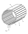
- FIG. 1 shows a stator shell 10 with a usual as in the prior art known smooth cylindrical surface.
- the inner surface of the stator shell is polygonal. Twelve surfaces 12, which are flat both in their length and in their width, are arranged next to one another around the inner circumference of the stator jacket. Two surfaces are always bounded by an intermediate edge 14 or are connected by an edge 14 with each other.
- each surface 12 has three grooves 16. The grooves run parallel to one another along the longitudinal axis of the stator shell 10. The spacing of the grooves 16 relative to each other is the same on each and every surface 12, 12 ', 12 ", 12'" and so on.
- a longitudinal slot 36 whose width depends inter alia on the diameter and the elasticity of the lining 18, divides the stator jacket on one side.
- a closure strip 20 engages with these two ends 22, 24 a positive connection and thus ensures that the stator jacket does not expand during pump operation.
- the strip may also be provided with a groove. So that the planar course of the inner surfaces 12, 12 ', 12 "is maintained, the ends 22, 24 are curved outwardly, whereby the closure strip in the outer region forms a positive connection and integrated into the surface course inside.
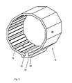
- Fig. 2 is a basically the same construction of the stator shell as in Fig.1 seen. Because of his in kind compared to Fig.1 smaller diameter here form only 10 polygonal arranged surfaces 12, the inner surface of the stator shell. Corresponding to the smaller flow rates and delivery heights required for smaller pumps counterpressure a double groove arrangement per polygonal surface is provided for this size. Due to the reduction of the material thickness in the area of the edges, this area is reinforced with ribs 26. The rib width corresponds to the spacing of the grooves 16. Both the ribs 26 and the platform 28 are provided as centering and as Vercardschutz.
- the Fig.2 shows the stator jacket without closure strip with the longitudinal slot 36 open.
- the stator shell 10 after Fig. 3 is polygonal on its inside and outside.
- the inner surfaces 12 and outer surfaces 30 are arranged congruently. All inner surfaces 12 each have three grooves 16 at equal distances from each other. If you choose the strength of the sealing strip less than that of the stator jacket so the closure strip simultaneously fulfills the function of a backup against overpressure.
- a liner 18 of the stator shell 10 shows Fig. 4 , Through the interior of the lining, a cavity 32 extends with a multi-thread in which the rotor of the pump rotates.
- the outer surface of the lining is polygonal shaped and has for this purpose a plurality of mutually parallel outer surfaces 34.
- the length of the liner in the disassembled state is always greater than that of the stator jacket.
- the stator lining is axially compressed during installation in the stator shell or in the eccentric screw and receives the required nominal dimensions for the pump cavity.
- the outer diameter of the stator lining has undersized in the removed state.
Landscapes
- Engineering & Computer Science (AREA)
- Mechanical Engineering (AREA)
- General Engineering & Computer Science (AREA)
- Rotary Pumps (AREA)
- Details And Applications Of Rotary Liquid Pumps (AREA)
Description
- Die Erfindung betrifft einen Stator einer Exzenterschneckenpumpe der aus einem Statormantel und einer elastischen beweglich im Statormantel angeordneten Auskleidung besteht.
- Aus der
DE 198 21 065 A1 geht hierzu ein Stator hervor, dessen Statormantel und Auskleidung schraubenförmig gestaltet sind. Beide Teile werden miteinander verschraubt, wodurch ein Verdrehen während des Pumpenbetriebes vermieden werden soll. Ebenso geht aus dieser Schrift hervor, daß Statorkombinationen, bei welchen der Statormantel an seiner Innenseite vorspringende Leisten aufweist, die in Nuten an der Oberfläche der Auskleidung eingreifen, ein Verdrehen beider Bauteile verhindern. - Die
Figur 4 derDE 1553126 A1 zeigt eine polygonförmige Auskleidung, die von einem ebenfalls polygonförmig gestalteten Statormantel umgeben ist. Die Auskleidung ist in diesem Beispiel zwar nicht einvulkanisiert, man benötigt für deren Entnahme aus dem Pumpenmantel jedoch eine Abziehvorrichtung. - Der
DE 29 07 392 A1 ist eine Gestaltung zur Verbesserung der Haftwirkung der Auskleidung mit dem Statormantel zu entnehmen. Hierzu weist die im Grunde genommen runde innere Oberfläche des Statormantels mehrere nutenförmige Vertiefungen auf, in die das elastische Material der Auskleidung einvulkanisiert wird. Eine axiale Beweglichkeit der Auskleidung ist damit nicht gegeben. - Bei diesen Ausführungsbeispielen bleibt jedoch unberücksichtigt, daß der in der Pumpe beim Pumpen erzeugte Druck die Auskleidung sehr fest an den Statormantel anpreßt, die anschließend und während des Betriebes der Pumpe nur noch unter hohem Kraftaufwand und zumeist nicht ohne mechanische Hilfsmittel bewegt, entfernt oder ausgetauscht werden kann.
- Aufgabe der Erfindung ist es demnach, den Statormantel so zu gestalten, daß dem Anhaften der Auskleidung entgegengewirkt wird.
- Gelöst wird diese Aufgabe mit den Merkmalen des Anspruchs 1. Weitere Ausgestaltungen der Erfindung gehen aus den Merkmalen der Unteransprüche hervor.
- Je nachdem mit welchen Druckverhältnissen, Produkten und Materialien bei einer Exzenterschneckenpumpe gearbeitet wird, entstehen Belastungen auf die Auskleidung. Diese Belastungen können naturgemäß früher oder später zum Austausch oder einer Korrektur der Lage der Auskleidung führen. Außerdem kann die axiale Beweglichkeit der Statorauskleidung im Statormantel für die optimale Einstellung der Statormaße notwendig sein. Mit dem Aufbau der herkömmlichen Statorkombinationen ist ein Austausch der Auskleidung bzw. ein Lageausgleich nur schwer möglich, da sich die Statorauskleidung sehr stark an die Innenfläche des Statormantels anlegt. Selbst bei bindemittelfreiem Anliegen der Auskleidung am Statormantel erfordern die entstehenden oder verursachten Anziehungs- und Ansaugkräfte hohe Gegenkräfte um die Auskleidung vom Statormantel zu entfernen bzw. gegenüber ihm beweglich zu halten. Erfindungsgemäß werden die erforderlichen Gegenkräfte durch die Reduzierung der Haftkräfte nahezu eliminiert, wozu Rillen in die Oberfläche der Innenseite des Statormantels eingebracht sind. Damit behält die Statorauskleidung auch während des Pumpenbetriebes ihre axiale Beweglichkeit.
- In einer bevorzugten Ausführung verlaufen die Rillen auf der inneren Oberfläche des Statormantels parallel zu dessen Längsachse. Damit oder mit der spiralförmigen Anordnung der Rillen wird die Haftwirkung gleichmäßig aufgehoben.
- Gemäß einer weiteren Ausführungsform ist der Querschnitt der Rillen an unterschiedlich elastisches Material für die Statorauskleidung angepaßt. So kann der Ablösevorgang beim Einsatz von stark elastischem Material und Rillen mit V-Form besser vonstatten gehen als bei winkelförmigen oder schwalbenschwanzförmig gestalteten Rillen. Diese Rillenform ist wiederum für geringelastisches Material besser geeignet, da hier die Eindringtiefe klein gehalten werden kann.
- Es hat sich gezeigt, daß Tiefen- und Breitenverhältnisse im Bereich von 1:1 bis 2:1 sehr gut geeignet sind, den Statoreinsatz während des Pumpenbetriebes vor dem Verdrehen zu bewahren und andererseits den Trennvorgang positiv zu unterstützen. Sollte sich die Auskleidung einmal nicht vom Statormantel ablösen, so könnte nur der bloße Stator zwischen einer Abschlußplatte und einem Druckmittelspeicher eingesetzt werden. Das anschließende Einbringen des Druckmittels (Gas, Flüssigkeit) in die Rillen würden den Ablösevorgang einleiten und beschleunigen.
- Ein weiteres Ausführungsbeispiel der Erfindung bezieht sich auf die polygone Querschnittsform des Statormantels und der Auskleidung. Je nachdem, welchen Förderquerschnitt die Exzenterschneckenpumpe benötigt und welche Reibung der Rotor im Stator erzeugt, muß ein Ausgleich zwischen der Kraft, die im Bereich der Rillen und dem Bereich der Kanten zwischen den polygonen Mantelflächen erzeugt wird, stattfinden, um einen unerwünschten Verschleiß der Auskleidung zu vermeiden. Die polygonförmige Gestaltung des Statormantels dient hier als optimale Fixierung der Statorauskleidung. Ab einer Kantenzahl von 8 Kanten aufwärts findet eine gleichmäßige Belastungsverteilung statt.
- Je nach Fördermenge und Förderdruck sind spezielle Rillenmengen und Rillenformen möglich. Bei allen Rillenformen ist darauf zu achten, daß alle Radien der Rillen einen Radius von 0,2 mm nicht unterschreiten, damit die Ver- und Rückformung des Materials der Auskleidung nicht behindert wird.
- Spezielle Produkte, die unter bestimmten Temperaturen gepumpt werden, beeinflussen die Statorauskleidung in den Teilbereichen unterschiedlich. So kann es entsprechend einer weiteren erfindungsgemäßen Ausführung vorteilhaft sein, wenn mindestens jede zweite Polygonfläche Rillen aufweist oder wenn in die Polygonflächen mindestens eine Rille eingebracht ist. Unterschiedlich können auch die verschiedenen Druckbereiche des Statormantels gestaltet sein. So kann z.B. im Bereich höherer Förder- oder Gegendruckwerte die Anzahl von Rillen erhöht oder deren Breite oder Tiefe vergrößert werden.
- Zur Vereinfachung der Montage und Demontage der Statorauskleidungen kann der Statormantel einen über die gesamte Länge durchgehenden Schlitz aufweisen, der eine geringfügige Weitung ermöglicht. Der Schlitz wird während des Betriebs der Pumpe durch eine Verschlußleiste abgedeckt und verkleinert. Somit steht der Statormantel im Betriebszustand unter einer Vorspannung, die sich beim Entfernen der Verschlußleiste löst und damit den Durchmesser des Statormantels weitet.
- Nach einem weiteren Ausführungsbeispiel ist das Längenmaß der Auskleidung nach der Fertigung größer als im eingebauten Zustand der Auskleidung in der betriebsbereiten Exzenterschneckenpumpe.
- Gemäß einem weiteren Ausführungsbeispiel hat die Verschlußleiste ein Leitungssystem mit dem ein Fluid zwischen den Statormantel und die Auskleidung gepreßt werden kann.
- Beispiele der Erfindung sind den nachfolgenden Zeichnungen zu entnehmen. Es zeigt:
- Fig. 1
- Statormantel für Exzenterschneckenpumpe
- Fig. 2
- dto.
- Fig. 3
- dto.
- Fig. 4
- Auskleidung für Statormantel
- Die
Figur 1 zeigt einen Statormantel 10 mit einer wie nach dem bisher bekannten Stand der Technik üblichen glatten zylindrischen Oberfläche. Die innere Oberfläche des Statormantels ist polygonförmig gestaltet. Zwölf sowohl in ihrer Länge als auch in ihrer Breite ebene Flächen 12 sind hier rings um den inneren Umfang des Statormantels aneinandergereiht. Zwei Flächen werden stets von einer dazwischenliegenden Kante 14 begrenzt bzw. sind durch eine Kante 14 miteinander verbunden. In diesem Ausführungsbeispiel weist jede Fläche 12 drei Rillen 16 auf. Die Rillen laufen parallel zueinander entlang der Längsachse des Statormantels 10. Der Abstand der Rillen 16 zueinander ist auf jeder und zu jeder Fläche 12, 12', 12", 12'" usw. gleich. Ein Längsschlitz 36, dessen Weite u.a. vom Durchmesser und der Elastizität der Auskleidung 18 abhängig ist, teilt den Statormantel an einer Seite. - Eine Verschlußleiste 20 geht mit diesen beiden Enden 22, 24 eine formschlüssige Verbindung ein und sichert damit, daß sich der Statormantel während des Pumpenbetriebs nicht aufweitet. Damit die erwünschten Antihafteigenschaften über den gesamten Innenumfang gleich bleiben, wofür die eingebrachten Rillen 16 sorgen, kann auch die Leiste mit einer Rille versehen sein. Damit der plane Verlauf der Innenflächen 12, 12', 12" beibehalten wird, sind die Enden 22, 24 nach außen gewölbt, wodurch die Verschlußleiste im Außenbereich einen Formschluß bildet und sich innen in den Flächenverlauf integriert.
- Aus
Fig. 2 ist ein prinzipiell gleicher Aufbau des Statormantels wie inFig.1 ersichtlich. Aufgrund seines in natura im Vergleich zuFig.1 kleineren Durchmessers bilden hier nur 10 polygonal angeordnete Flächen 12 die innere Oberfläche des Statormantels. Entsprechend dem bei kleineren Pumpen benötigten kleineren Fördermengen und Förderhöhen abhängigen Gegendruck ist für diese Baugröße eine doppelte Rillenanordnung pro Polygonfläche vorgesehen. Aufgrund der Reduzierung der Materialstärke im Bereich der Kanten ist dieser Bereich mit Rippen 26 verstärkt. Die Rippenbreite entspricht dem Abstand der Rillen 16. Sowohl die Rippen 26 als auch die Plattform 28 sind als Zentrierhilfe und als Verdrehschutz vorgesehen. DieFig.2 zeigt den Statormantel ohne Verschlußleiste mit geöffnetem Längsschlitz 36. - Der Statormantel 10 nach
Fig. 3 ist auf seiner Innen- und Außenseite polygonförmig gestaltet. Die Innenflächen 12 und Außenflächen 30 sind deckungsgleich angeordnet. Alle Innenflächen 12 weisen jeweils drei Rillen 16 in gleichen Abständen voneinander auf. Wählt man die Festigkeit der Verschlußleiste geringer als die des Statormantels so erfüllt die Verschlußleiste gleichzeitig die Funktion einer Sicherung gegen Überdruck. - Eine Auskleidung 18 des Statormantels 10 zeigt
Fig. 4 . Durch das Innere der Auskleidung erstreckt sich ein Hohlraum 32 mit einem mehrgängigen Gewinde in dem der Rotor der Pumpe umläuft. Die äußere Oberfläche der Auskleidung ist polygonförmig gestaltet und hat hierzu mehrere parallel zueinander angeordnete Außenflächen 34. Die Länge der Auskleidung im ausgebauten Zustand ist stets größer als die des Statormantels. Dadurch wird die Statorauskleidung beim Einbau in den Statormantel bzw. in die Exzenterschneckenpumpe axial zusammengedrückt und erhält die erforderlichen Nennmaße für den Pumpenhohlraum. Der Außendurchmesser der Statorauskleidung hat demnach im ausgebauten Zustand Untermaß. -
- 10
- Statormantel
- 12
- Innenfläche
- 14
- Kante
- 16
- Rillen
- 18
- Auskleidung
- 20
- Verschlußleiste
- 22
- Enden
- 24
- Enden
- 26
- Rippen
- 28
- Plattform
- 30
- Außenfläche
- 32
- Hohlraum
- 34
- Außenfläche
- 36
- Schlitz
Claims (15)
- Statormantel (10) für Exzenterschneckenpumpen an dessen innerer Oberfläche, die polygonförmig gestaltet ist, eine elastische Auskleidung (18) axial beweglich anliegt, dadurch gekennzeichnet dass in die einzelnen Polygonflächen mindestens eine Rille (16) eingebracht ist, die die Haftwirkung zwischen der Auskleidung und dem Statormantel reduziert.
- Statormantel nach Anspruch 1,
dadurch gekennzeichnet,
daß die Rillen (16) parallel zur Längsachse angeordnet sind. - Statormantel nach Anspruch 1,
dadurch gekennzeichnet,
daß die Rillen (16) im Querschnitt rechteckig, V-förmig, rund oder winkelförmig geformt sind. - Statormantel nach den Ansprüchen 1 oder 2,
dadurch gekennzeichnet,
daß das Verhältnis von Rillentiefe zu Rillenbreite 1 : 1 ist. - Statormantel nach den Ansprüchen 1 oder 2,
dadurch gekennzeichnet,
daß das Verhältnis der Rillentiefe zur Rillenbreite > als 1, insbesondere 1,5 : 1 ist. - Statormantel nach Anspruch 1,
dadurch gekennzeichnet,
daß mindestens jede zweite Polygonfläche Rillen (16) aufweist. - Statormantel nach Anspruch 1,
dadurch gekennzeichnet,
daß der Statormantel (10) einen durchgehenden Schlitz (36) aufweist. - Statormantel nach Anspruch 7,
dadurch gekennzeichnet,
daß der Schlitz (36) von einer Verschlußleiste (20) bedeckt wird. - Statormantel nach Anspruch 8,
dadurch gekennzeichnet,
daß die Verschlußleiste (20) und der Statormantel (10) Längsrillen (16) bilden. - Statormantel nach Anspruch 1,
dadurch gekennzeichnet,
daß der Statormantel (10) eine entlang dessen Längsachse sich erstreckende Verschlußleiste (20) aufweist. - Statormantel nach Anspruch 1,
dadurch gekennzeichnet,
daß die innere Oberfläche des Statormantels eine Antihaftbeschichtung (z.B. PTFE-Lack) aufweist. - Statormantel nach Anspruch 8,
dadurch gekennzeichnet,
daß die Verschlußleiste (20) aus dem gleichen oder verschiedenen Materialien (Kunststoff, Aluminium, Chromnickelstahl) wie der Statormantel besteht. - Statormantel nach Anspruch 1,
dadurch gekennzeichnet,
daß die innere Oberfläche z.B. mittels Sandstrahlen angerauht ist. - Statormantel nach Anspruch 1,
dadurch gekennzeichnet,
daß die äußere Oberfläche der Auskleidung mit einer Antihaftbeschichtung, z.B. PTFE-Lack versehen ist. - Statormantel nach Anspruch 1,
dadurch gekennzeichnet,
daß die äußere Oberfläche des Statormantels mit Rippen (26) entlang der Längsachse versehen ist.
Priority Applications (2)
| Application Number | Priority Date | Filing Date | Title |
|---|---|---|---|
| PL07722396T PL2018478T3 (pl) | 2006-05-11 | 2007-05-10 | Płaszcz stojana dla mimośrodowych pomp ślimakowych |
| SI200730945T SI2018478T1 (sl) | 2006-05-11 | 2007-05-10 | Plaĺ äś statorja za ekscentriäśne polĺ˝ne äśrpalke |
Applications Claiming Priority (2)
| Application Number | Priority Date | Filing Date | Title |
|---|---|---|---|
| DE102006021897A DE102006021897B4 (de) | 2006-05-11 | 2006-05-11 | Statormantel für Exzenterschneckenpumpen |
| PCT/DE2007/000845 WO2007131476A1 (de) | 2006-05-11 | 2007-05-10 | Statormantel für exzenterschneckenpumpen |
Publications (2)
| Publication Number | Publication Date |
|---|---|
| EP2018478A1 EP2018478A1 (de) | 2009-01-28 |
| EP2018478B1 true EP2018478B1 (de) | 2012-04-04 |
Family
ID=38445698
Family Applications (1)
| Application Number | Title | Priority Date | Filing Date |
|---|---|---|---|
| EP07722396A Not-in-force EP2018478B1 (de) | 2006-05-11 | 2007-05-10 | Statormantel für exzenterschneckenpumpen |
Country Status (21)
| Country | Link |
|---|---|
| US (1) | US8033802B2 (de) |
| EP (1) | EP2018478B1 (de) |
| JP (1) | JP4886028B2 (de) |
| KR (1) | KR101161915B1 (de) |
| CN (1) | CN101443556B (de) |
| AT (1) | ATE552422T1 (de) |
| AU (1) | AU2007250390B2 (de) |
| BR (1) | BRPI0712528B1 (de) |
| CA (1) | CA2651133A1 (de) |
| DE (1) | DE102006021897B4 (de) |
| DK (1) | DK2018478T3 (de) |
| ES (1) | ES2385258T3 (de) |
| MX (1) | MX2008014335A (de) |
| MY (1) | MY149088A (de) |
| NZ (1) | NZ573585A (de) |
| PL (1) | PL2018478T3 (de) |
| PT (1) | PT2018478E (de) |
| RU (1) | RU2398134C1 (de) |
| SI (1) | SI2018478T1 (de) |
| WO (1) | WO2007131476A1 (de) |
| ZA (1) | ZA200809578B (de) |
Families Citing this family (20)
| Publication number | Priority date | Publication date | Assignee | Title |
|---|---|---|---|---|
| US9051780B2 (en) * | 2007-01-09 | 2015-06-09 | Schlumberger Technology Corporation | Progressive cavity hydraulic machine |
| US9309767B2 (en) | 2010-08-16 | 2016-04-12 | National Oilwell Varco, L.P. | Reinforced stators and fabrication methods |
| RU2468306C2 (ru) * | 2010-11-03 | 2012-11-27 | Валерий Никитич Гринавцев | Разогреватель турбулентный |
| US8672656B2 (en) * | 2010-12-20 | 2014-03-18 | Robbins & Myers Energy Systems L.P. | Progressing cavity pump/motor |
| JP5821058B2 (ja) * | 2010-12-27 | 2015-11-24 | 兵神装備株式会社 | 一軸偏心ねじポンプ |
| US8905733B2 (en) * | 2011-04-07 | 2014-12-09 | Robbins & Myers Energy Systems L.P. | Progressing cavity pump/motor |
| GB2551304B (en) | 2012-02-22 | 2018-02-28 | Nat Oilwell Varco Lp | Stator for progressive cavity pump/motor |
| DE102012112044B4 (de) * | 2012-05-04 | 2015-10-08 | Netzsch Pumpen & Systeme Gmbh | Selbstfixierendes Statorgehäuse |
| DE102012008761B4 (de) * | 2012-05-05 | 2016-01-21 | Netzsch Pumpen & Systeme Gmbh | Geteilter Statormantel |
| DE202013004219U1 (de) | 2013-05-06 | 2013-05-17 | SGF SüDDEUTSCHE GELENKSCHEIBENFABRIK GMBH & CO. KG | Stator für eine Förderpumpe |
| CN106685152B (zh) * | 2015-11-10 | 2019-03-12 | 耐驰(兰州)泵业有限公司 | 制造用于偏心螺杆泵的可液压调整的定子的方法 |
| DE102017126002B3 (de) | 2017-11-07 | 2019-02-14 | Seepex Gmbh | Exzenterschneckenpumpe |
| CN108788642A (zh) * | 2018-06-21 | 2018-11-13 | 苏州利德精工制造有限公司 | 真空泵定子加工方法 |
| WO2020051692A1 (en) | 2018-09-11 | 2020-03-19 | Rotoliptic Technologies Incorporated | Sealing in helical trochoidal rotary machines |
| US11815094B2 (en) | 2020-03-10 | 2023-11-14 | Rotoliptic Technologies Incorporated | Fixed-eccentricity helical trochoidal rotary machines |
| CA3115512C (en) * | 2020-04-21 | 2023-08-22 | Roper Pump Company | Stator with modular interior |
| US11802558B2 (en) | 2020-12-30 | 2023-10-31 | Rotoliptic Technologies Incorporated | Axial load in helical trochoidal rotary machines |
| CA3177204A1 (en) | 2021-01-08 | 2022-07-14 | Rotoliptic Technologies Incorporated | Rotary machines with teardrop-shaped rotors |
| US12146492B2 (en) | 2021-01-08 | 2024-11-19 | Rotoliptic Technologies Incorporated | Helical trochoidal rotary machines with improved solids handling |
| CN114810579B (zh) * | 2022-04-24 | 2024-02-27 | 上海申贝泵业制造有限公司 | 一种单螺杆泵 |
Family Cites Families (18)
| Publication number | Priority date | Publication date | Assignee | Title |
|---|---|---|---|---|
| US3011445A (en) * | 1957-11-13 | 1961-12-05 | Robbin & Myers Inc | Helical gear pump with by-pass |
| DE1553126A1 (de) * | 1965-11-18 | 1971-03-04 | A Hoelz Kg Maschf | Schneckenpumpe |
| US3489231A (en) * | 1967-09-19 | 1970-01-13 | Smith International | Lubricating mud metering device |
| US4025751A (en) * | 1975-04-28 | 1977-05-24 | Xerox Corporation | Fuser roll sleeve |
| DE2907392C2 (de) * | 1979-02-26 | 1982-10-14 | Dietrich Dipl.-Ing. 6240 Königstein Maurer | Nachstellbarer Stator für Exzenterschneckenpumpen |
| DE2930068A1 (de) * | 1979-07-25 | 1981-03-19 | Kurt-Joachim 3000 Hannover Ganz | Exzenter-schnecken-verdraengungspumpe |
| US4313717A (en) * | 1979-10-04 | 1982-02-02 | Kopecky Eugene F | Adjustable pressure extrusion pump |
| DE3312197A1 (de) * | 1983-04-02 | 1984-10-04 | Gummi-Jäger KG GmbH & Cie, 3000 Hannover | Nachstellbarer stator fuer exzenterschneckenpumpen |
| HU204116B (en) * | 1989-01-23 | 1991-11-28 | Hidromechanika Szivattyu Es An | Arrangement for the standing part of eccentric worm pump |
| JPH03100447U (de) * | 1990-01-31 | 1991-10-21 | ||
| DE4237966A1 (de) * | 1992-11-11 | 1994-05-26 | Arnold Jaeger | Exzenterschneckenpumpe |
| DE19811889A1 (de) * | 1998-03-18 | 1999-09-30 | Usd Formteiltechnik Gmbh | Spannschelle |
| JPH11303765A (ja) * | 1998-04-23 | 1999-11-02 | Ricoh Co Ltd | スクリューポンプ |
| DE19821065A1 (de) * | 1998-05-12 | 1999-11-18 | Artemis Kautschuk Kunststoff | Elastomerstator für Exzenterschneckenpumpen |
| DE10022631C2 (de) * | 2000-05-11 | 2002-08-08 | Gruen Pumpen Gmbh | Exzenterschnecken-Faßpumpe |
| DE10241753C1 (de) * | 2002-09-10 | 2003-11-13 | Netzsch Mohnopumpen Gmbh | Stator für Exzenterschneckenpumpe |
| CN1421613A (zh) * | 2002-12-22 | 2003-06-04 | 崔乃林 | 用聚合材料和陶瓷制造的螺杆泵及其制造方法 |
| DE102005042559A1 (de) * | 2005-09-08 | 2007-03-15 | Netzsch-Mohnopumpen Gmbh | Statorsystem |
-
2006
- 2006-05-11 DE DE102006021897A patent/DE102006021897B4/de not_active Withdrawn - After Issue
-
2007
- 2007-05-10 WO PCT/DE2007/000845 patent/WO2007131476A1/de not_active Ceased
- 2007-05-10 JP JP2009508123A patent/JP4886028B2/ja not_active Expired - Fee Related
- 2007-05-10 BR BRPI0712528-3A patent/BRPI0712528B1/pt not_active IP Right Cessation
- 2007-05-10 DK DK07722396.4T patent/DK2018478T3/da active
- 2007-05-10 KR KR1020087030124A patent/KR101161915B1/ko not_active Expired - Fee Related
- 2007-05-10 ES ES07722396T patent/ES2385258T3/es active Active
- 2007-05-10 AT AT07722396T patent/ATE552422T1/de active
- 2007-05-10 MY MYPI20084506A patent/MY149088A/en unknown
- 2007-05-10 RU RU2008148604/06A patent/RU2398134C1/ru not_active IP Right Cessation
- 2007-05-10 SI SI200730945T patent/SI2018478T1/sl unknown
- 2007-05-10 EP EP07722396A patent/EP2018478B1/de not_active Not-in-force
- 2007-05-10 PL PL07722396T patent/PL2018478T3/pl unknown
- 2007-05-10 CN CN200780017108XA patent/CN101443556B/zh not_active Expired - Fee Related
- 2007-05-10 NZ NZ573585A patent/NZ573585A/en not_active IP Right Cessation
- 2007-05-10 PT PT07722396T patent/PT2018478E/pt unknown
- 2007-05-10 MX MX2008014335A patent/MX2008014335A/es active IP Right Grant
- 2007-05-10 AU AU2007250390A patent/AU2007250390B2/en not_active Ceased
- 2007-05-10 CA CA002651133A patent/CA2651133A1/en not_active Abandoned
-
2008
- 2008-11-10 ZA ZA200809578A patent/ZA200809578B/xx unknown
- 2008-11-10 US US12/268,078 patent/US8033802B2/en not_active Expired - Fee Related
Also Published As
| Publication number | Publication date |
|---|---|
| JP4886028B2 (ja) | 2012-02-29 |
| MY149088A (en) | 2013-07-15 |
| PT2018478E (pt) | 2012-07-04 |
| ES2385258T3 (es) | 2012-07-20 |
| RU2008148604A (ru) | 2010-06-20 |
| NZ573585A (en) | 2011-03-31 |
| MX2008014335A (es) | 2008-11-27 |
| US8033802B2 (en) | 2011-10-11 |
| ATE552422T1 (de) | 2012-04-15 |
| EP2018478A1 (de) | 2009-01-28 |
| JP2009536703A (ja) | 2009-10-15 |
| DE102006021897A1 (de) | 2007-11-15 |
| RU2398134C1 (ru) | 2010-08-27 |
| KR101161915B1 (ko) | 2012-07-03 |
| CN101443556A (zh) | 2009-05-27 |
| DE102006021897B4 (de) | 2009-11-19 |
| AU2007250390A1 (en) | 2007-11-22 |
| PL2018478T3 (pl) | 2012-09-28 |
| KR20090011022A (ko) | 2009-01-30 |
| CN101443556B (zh) | 2011-08-03 |
| AU2007250390B2 (en) | 2012-05-24 |
| ZA200809578B (en) | 2009-09-30 |
| BRPI0712528A2 (pt) | 2012-09-04 |
| BRPI0712528B1 (pt) | 2019-06-25 |
| US20090074599A1 (en) | 2009-03-19 |
| DK2018478T3 (da) | 2012-07-16 |
| WO2007131476A1 (de) | 2007-11-22 |
| CA2651133A1 (en) | 2007-11-22 |
| SI2018478T1 (sl) | 2012-08-31 |
Similar Documents
| Publication | Publication Date | Title |
|---|---|---|
| WO2007131476A1 (de) | Statormantel für exzenterschneckenpumpen | |
| EP3187736B1 (de) | Mehrstufige horizontale zentrifugalpumpe zum fördern eines fluids sowie verfahren zum instandsetzen einer solchen | |
| WO1997033108A1 (de) | Dichtung für einen ringkolben einer hydraulischen kupplungs-ausrückvorrichtung | |
| DE3001671A1 (de) | Matrize fuer massivumformung im kalt- oder halbwarmverfahren | |
| DE2817280A1 (de) | Stator fuer exzenterschneckenpumpen | |
| DE102010003077B4 (de) | Gleitlagerschale | |
| EP1446597B1 (de) | In segmente unterteilter ölabstreifring | |
| AT396889B (de) | Anordnung zum abdichten von plungern von hochdruckeinrichtungen | |
| WO2025031823A1 (de) | Stator für eine exzenterschneckenpumpe | |
| DE102011121768B4 (de) | Axialgleitlager | |
| EP3290552B1 (de) | Galettenwalze | |
| EP1282777B1 (de) | Drehkolbenpumpe | |
| DE102017126002B3 (de) | Exzenterschneckenpumpe | |
| EP1884687B9 (de) | Seilscheibe | |
| EP3498895A1 (de) | Auflösewalze für eine offenend-spinnvorrichtung sowie offenend-spinnvorrichtung | |
| EP3467319A1 (de) | Kreiselpumpe mit verbesserter saughalsdichtung | |
| DE102020114937B4 (de) | Exzenterschneckenpumpe in modularer bauweise | |
| DE3111726C1 (de) | Dichtungsring | |
| DE3045192A1 (de) | Zahnradpumpe | |
| EP0380050A2 (de) | Anordnung des Stators von exzentrischen Spiralpumpen | |
| DE2505261C3 (de) | Statornachstellvorrichtung bei einer Exzenterschneckenpumpe für zähflüssige Medien | |
| DE102007044901B4 (de) | Zylinderrollenlagerkäfig und Rollenlagerung | |
| DE102023115951A1 (de) | Statorauskleidung, Stator sowie Verfahren zum Herstellen einer Statorauskleidung | |
| DE102024116869A1 (de) | Kreiselpumpenanordnung | |
| DE1303705B (de) | Axial foerdernde verdraengerpumpe mit rotierendem pumpelement |
Legal Events
| Date | Code | Title | Description |
|---|---|---|---|
| PUAI | Public reference made under article 153(3) epc to a published international application that has entered the european phase |
Free format text: ORIGINAL CODE: 0009012 |
|
| 17P | Request for examination filed |
Effective date: 20081211 |
|
| AK | Designated contracting states |
Kind code of ref document: A1 Designated state(s): AT BE BG CH CY CZ DE DK EE ES FI FR GB GR HU IE IS IT LI LT LU LV MC MT NL PL PT RO SE SI SK TR |
|
| AX | Request for extension of the european patent |
Extension state: AL BA HR MK RS |
|
| GRAP | Despatch of communication of intention to grant a patent |
Free format text: ORIGINAL CODE: EPIDOSNIGR1 |
|
| DAX | Request for extension of the european patent (deleted) | ||
| GRAS | Grant fee paid |
Free format text: ORIGINAL CODE: EPIDOSNIGR3 |
|
| GRAA | (expected) grant |
Free format text: ORIGINAL CODE: 0009210 |
|
| AK | Designated contracting states |
Kind code of ref document: B1 Designated state(s): AT BE BG CH CY CZ DE DK EE ES FI FR GB GR HU IE IS IT LI LT LU LV MC MT NL PL PT RO SE SI SK TR |
|
| REG | Reference to a national code |
Ref country code: GB Ref legal event code: FG4D Free format text: NOT ENGLISH |
|
| REG | Reference to a national code |
Ref country code: CH Ref legal event code: EP |
|
| REG | Reference to a national code |
Ref country code: AT Ref legal event code: REF Ref document number: 552422 Country of ref document: AT Kind code of ref document: T Effective date: 20120415 |
|
| REG | Reference to a national code |
Ref country code: IE Ref legal event code: FG4D Free format text: LANGUAGE OF EP DOCUMENT: GERMAN |
|
| REG | Reference to a national code |
Ref country code: DE Ref legal event code: R096 Ref document number: 502007009615 Country of ref document: DE Effective date: 20120531 |
|
| REG | Reference to a national code |
Ref country code: RO Ref legal event code: EPE |
|
| REG | Reference to a national code |
Ref country code: PT Ref legal event code: SC4A Free format text: AVAILABILITY OF NATIONAL TRANSLATION Effective date: 20120628 |
|
| REG | Reference to a national code |
Ref country code: SE Ref legal event code: TRGR |
|
| REG | Reference to a national code |
Ref country code: CH Ref legal event code: NV Representative=s name: PATENTANWAELTE SCHAAD, BALASS, MENZL & PARTNER AG |
|
| REG | Reference to a national code |
Ref country code: DK Ref legal event code: T3 |
|
| REG | Reference to a national code |
Ref country code: ES Ref legal event code: FG2A Ref document number: 2385258 Country of ref document: ES Kind code of ref document: T3 Effective date: 20120720 |
|
| REG | Reference to a national code |
Ref country code: NL Ref legal event code: VDEP Effective date: 20120404 |
|
| REG | Reference to a national code |
Ref country code: SK Ref legal event code: T3 Ref document number: E 11998 Country of ref document: SK |
|
| REG | Reference to a national code |
Ref country code: PL Ref legal event code: T3 |
|
| REG | Reference to a national code |
Ref country code: EE Ref legal event code: FG4A Ref document number: E007002 Country of ref document: EE Effective date: 20120628 |
|
| PG25 | Lapsed in a contracting state [announced via postgrant information from national office to epo] |
Ref country code: CY Free format text: LAPSE BECAUSE OF FAILURE TO SUBMIT A TRANSLATION OF THE DESCRIPTION OR TO PAY THE FEE WITHIN THE PRESCRIBED TIME-LIMIT Effective date: 20120404 |
|
| BERE | Be: lapsed |
Owner name: NETZSCH-MOHNOPUMPEN G.M.B.H. Effective date: 20120531 |
|
| PG25 | Lapsed in a contracting state [announced via postgrant information from national office to epo] |
Ref country code: GR Free format text: LAPSE BECAUSE OF FAILURE TO SUBMIT A TRANSLATION OF THE DESCRIPTION OR TO PAY THE FEE WITHIN THE PRESCRIBED TIME-LIMIT Effective date: 20120705 |
|
| PG25 | Lapsed in a contracting state [announced via postgrant information from national office to epo] |
Ref country code: MC Free format text: LAPSE BECAUSE OF NON-PAYMENT OF DUE FEES Effective date: 20120531 |
|
| PG25 | Lapsed in a contracting state [announced via postgrant information from national office to epo] |
Ref country code: NL Free format text: LAPSE BECAUSE OF FAILURE TO SUBMIT A TRANSLATION OF THE DESCRIPTION OR TO PAY THE FEE WITHIN THE PRESCRIBED TIME-LIMIT Effective date: 20120404 |
|
| PLBE | No opposition filed within time limit |
Free format text: ORIGINAL CODE: 0009261 |
|
| STAA | Information on the status of an ep patent application or granted ep patent |
Free format text: STATUS: NO OPPOSITION FILED WITHIN TIME LIMIT |
|
| PG25 | Lapsed in a contracting state [announced via postgrant information from national office to epo] |
Ref country code: BE Free format text: LAPSE BECAUSE OF NON-PAYMENT OF DUE FEES Effective date: 20120531 |
|
| 26N | No opposition filed |
Effective date: 20130107 |
|
| REG | Reference to a national code |
Ref country code: DE Ref legal event code: R097 Ref document number: 502007009615 Country of ref document: DE Effective date: 20130107 |
|
| REG | Reference to a national code |
Ref country code: AT Ref legal event code: MM01 Ref document number: 552422 Country of ref document: AT Kind code of ref document: T Effective date: 20120510 |
|
| PG25 | Lapsed in a contracting state [announced via postgrant information from national office to epo] |
Ref country code: MT Free format text: LAPSE BECAUSE OF FAILURE TO SUBMIT A TRANSLATION OF THE DESCRIPTION OR TO PAY THE FEE WITHIN THE PRESCRIBED TIME-LIMIT Effective date: 20120404 Ref country code: BG Free format text: LAPSE BECAUSE OF NON-PAYMENT OF DUE FEES Effective date: 20121231 Ref country code: AT Free format text: LAPSE BECAUSE OF NON-PAYMENT OF DUE FEES Effective date: 20120510 |
|
| REG | Reference to a national code |
Ref country code: ES Ref legal event code: PC2A Owner name: NETZSCH PUMPEN AND SYSTEME GMBH Effective date: 20131028 |
|
| PG25 | Lapsed in a contracting state [announced via postgrant information from national office to epo] |
Ref country code: LU Free format text: LAPSE BECAUSE OF NON-PAYMENT OF DUE FEES Effective date: 20120510 |
|
| PG25 | Lapsed in a contracting state [announced via postgrant information from national office to epo] |
Ref country code: HU Free format text: LAPSE BECAUSE OF FAILURE TO SUBMIT A TRANSLATION OF THE DESCRIPTION OR TO PAY THE FEE WITHIN THE PRESCRIBED TIME-LIMIT Effective date: 20070510 |
|
| PGFP | Annual fee paid to national office [announced via postgrant information from national office to epo] |
Ref country code: SK Payment date: 20150427 Year of fee payment: 9 Ref country code: SI Payment date: 20150424 Year of fee payment: 9 Ref country code: EE Payment date: 20150518 Year of fee payment: 9 Ref country code: BG Payment date: 20150529 Year of fee payment: 9 Ref country code: CZ Payment date: 20150423 Year of fee payment: 9 Ref country code: PT Payment date: 20150423 Year of fee payment: 9 Ref country code: RO Payment date: 20150430 Year of fee payment: 9 Ref country code: SE Payment date: 20150516 Year of fee payment: 9 Ref country code: LT Payment date: 20150421 Year of fee payment: 9 Ref country code: DK Payment date: 20150516 Year of fee payment: 9 Ref country code: CH Payment date: 20150516 Year of fee payment: 9 Ref country code: FI Payment date: 20150513 Year of fee payment: 9 |
|
| PGFP | Annual fee paid to national office [announced via postgrant information from national office to epo] |
Ref country code: IE Payment date: 20150512 Year of fee payment: 9 Ref country code: PL Payment date: 20150422 Year of fee payment: 9 Ref country code: LV Payment date: 20150525 Year of fee payment: 9 Ref country code: IS Payment date: 20150427 Year of fee payment: 9 |
|
| REG | Reference to a national code |
Ref country code: FR Ref legal event code: PLFP Year of fee payment: 10 |
|
| REG | Reference to a national code |
Ref country code: LT Ref legal event code: MM4D Effective date: 20160510 |
|
| REG | Reference to a national code |
Ref country code: EE Ref legal event code: MM4A Ref document number: E007002 Country of ref document: EE Effective date: 20160531 |
|
| REG | Reference to a national code |
Ref country code: CH Ref legal event code: PL |
|
| REG | Reference to a national code |
Ref country code: DK Ref legal event code: EBP Effective date: 20160531 |
|
| PG25 | Lapsed in a contracting state [announced via postgrant information from national office to epo] |
Ref country code: EE Free format text: LAPSE BECAUSE OF NON-PAYMENT OF DUE FEES Effective date: 20160531 Ref country code: IS Free format text: LAPSE BECAUSE OF FAILURE TO SUBMIT A TRANSLATION OF THE DESCRIPTION OR TO PAY THE FEE WITHIN THE PRESCRIBED TIME-LIMIT Effective date: 20161201 Ref country code: CZ Free format text: LAPSE BECAUSE OF NON-PAYMENT OF DUE FEES Effective date: 20160510 Ref country code: RO Free format text: LAPSE BECAUSE OF NON-PAYMENT OF DUE FEES Effective date: 20160510 Ref country code: FI Free format text: LAPSE BECAUSE OF NON-PAYMENT OF DUE FEES Effective date: 20160510 Ref country code: SK Free format text: LAPSE BECAUSE OF NON-PAYMENT OF DUE FEES Effective date: 20160510 Ref country code: LT Free format text: LAPSE BECAUSE OF NON-PAYMENT OF DUE FEES Effective date: 20160510 Ref country code: LI Free format text: LAPSE BECAUSE OF NON-PAYMENT OF DUE FEES Effective date: 20160531 Ref country code: CH Free format text: LAPSE BECAUSE OF NON-PAYMENT OF DUE FEES Effective date: 20160531 |
|
| REG | Reference to a national code |
Ref country code: SK Ref legal event code: MM4A Ref document number: E 11998 Country of ref document: SK Effective date: 20160510 |
|
| REG | Reference to a national code |
Ref country code: IE Ref legal event code: MM4A |
|
| PG25 | Lapsed in a contracting state [announced via postgrant information from national office to epo] |
Ref country code: PT Free format text: LAPSE BECAUSE OF NON-PAYMENT OF DUE FEES Effective date: 20161110 Ref country code: SE Free format text: LAPSE BECAUSE OF NON-PAYMENT OF DUE FEES Effective date: 20160511 Ref country code: BG Free format text: LAPSE BECAUSE OF NON-PAYMENT OF DUE FEES Effective date: 20161130 Ref country code: LV Free format text: LAPSE BECAUSE OF NON-PAYMENT OF DUE FEES Effective date: 20160510 |
|
| REG | Reference to a national code |
Ref country code: SI Ref legal event code: KO00 Effective date: 20170216 |
|
| REG | Reference to a national code |
Ref country code: FR Ref legal event code: PLFP Year of fee payment: 11 |
|
| PG25 | Lapsed in a contracting state [announced via postgrant information from national office to epo] |
Ref country code: IE Free format text: LAPSE BECAUSE OF NON-PAYMENT OF DUE FEES Effective date: 20160510 Ref country code: DK Free format text: LAPSE BECAUSE OF NON-PAYMENT OF DUE FEES Effective date: 20160531 Ref country code: SI Free format text: LAPSE BECAUSE OF NON-PAYMENT OF DUE FEES Effective date: 20160511 |
|
| PG25 | Lapsed in a contracting state [announced via postgrant information from national office to epo] |
Ref country code: PL Free format text: LAPSE BECAUSE OF NON-PAYMENT OF DUE FEES Effective date: 20160510 |
|
| REG | Reference to a national code |
Ref country code: FR Ref legal event code: PLFP Year of fee payment: 12 |
|
| PGFP | Annual fee paid to national office [announced via postgrant information from national office to epo] |
Ref country code: ES Payment date: 20180618 Year of fee payment: 12 |
|
| REG | Reference to a national code |
Ref country code: ES Ref legal event code: FD2A Effective date: 20200925 |
|
| PG25 | Lapsed in a contracting state [announced via postgrant information from national office to epo] |
Ref country code: ES Free format text: LAPSE BECAUSE OF NON-PAYMENT OF DUE FEES Effective date: 20190511 |
|
| PGFP | Annual fee paid to national office [announced via postgrant information from national office to epo] |
Ref country code: FR Payment date: 20210522 Year of fee payment: 15 Ref country code: IT Payment date: 20210531 Year of fee payment: 15 Ref country code: DE Payment date: 20210521 Year of fee payment: 15 |
|
| PGFP | Annual fee paid to national office [announced via postgrant information from national office to epo] |
Ref country code: GB Payment date: 20210522 Year of fee payment: 15 |
|
| PG25 | Lapsed in a contracting state [announced via postgrant information from national office to epo] |
Ref country code: TR Free format text: LAPSE BECAUSE OF NON-PAYMENT OF DUE FEES Effective date: 20190510 |
|
| REG | Reference to a national code |
Ref country code: DE Ref legal event code: R119 Ref document number: 502007009615 Country of ref document: DE |
|
| GBPC | Gb: european patent ceased through non-payment of renewal fee |
Effective date: 20220510 |
|
| PG25 | Lapsed in a contracting state [announced via postgrant information from national office to epo] |
Ref country code: FR Free format text: LAPSE BECAUSE OF NON-PAYMENT OF DUE FEES Effective date: 20220531 |
|
| PG25 | Lapsed in a contracting state [announced via postgrant information from national office to epo] |
Ref country code: GB Free format text: LAPSE BECAUSE OF NON-PAYMENT OF DUE FEES Effective date: 20220510 Ref country code: DE Free format text: LAPSE BECAUSE OF NON-PAYMENT OF DUE FEES Effective date: 20221201 |
|
| PG25 | Lapsed in a contracting state [announced via postgrant information from national office to epo] |
Ref country code: IT Free format text: LAPSE BECAUSE OF NON-PAYMENT OF DUE FEES Effective date: 20220510 |