EP2018954B1 - Appareil et procédé pour humecter des lentilles de contact - Google Patents
Appareil et procédé pour humecter des lentilles de contact Download PDFInfo
- Publication number
- EP2018954B1 EP2018954B1 EP08104614.6A EP08104614A EP2018954B1 EP 2018954 B1 EP2018954 B1 EP 2018954B1 EP 08104614 A EP08104614 A EP 08104614A EP 2018954 B1 EP2018954 B1 EP 2018954B1
- Authority
- EP
- European Patent Office
- Prior art keywords
- lens
- wetting
- profile
- liquid solution
- tank
- Prior art date
- Legal status (The legal status is an assumption and is not a legal conclusion. Google has not performed a legal analysis and makes no representation as to the accuracy of the status listed.)
- Active
Links
Images


Classifications
-
- B—PERFORMING OPERATIONS; TRANSPORTING
- B29—WORKING OF PLASTICS; WORKING OF SUBSTANCES IN A PLASTIC STATE IN GENERAL
- B29D—PRODUCING PARTICULAR ARTICLES FROM PLASTICS OR FROM SUBSTANCES IN A PLASTIC STATE
- B29D11/00—Producing optical elements, e.g. lenses or prisms
- B29D11/00009—Production of simple or compound lenses
- B29D11/00038—Production of contact lenses
- B29D11/00067—Hydrating contact lenses
-
- B—PERFORMING OPERATIONS; TRANSPORTING
- B29—WORKING OF PLASTICS; WORKING OF SUBSTANCES IN A PLASTIC STATE IN GENERAL
- B29D—PRODUCING PARTICULAR ARTICLES FROM PLASTICS OR FROM SUBSTANCES IN A PLASTIC STATE
- B29D11/00—Producing optical elements, e.g. lenses or prisms
- B29D11/00009—Production of simple or compound lenses
-
- B—PERFORMING OPERATIONS; TRANSPORTING
- B29—WORKING OF PLASTICS; WORKING OF SUBSTANCES IN A PLASTIC STATE IN GENERAL
- B29D—PRODUCING PARTICULAR ARTICLES FROM PLASTICS OR FROM SUBSTANCES IN A PLASTIC STATE
- B29D11/00—Producing optical elements, e.g. lenses or prisms
- B29D11/00865—Applying coatings; tinting; colouring
-
- B—PERFORMING OPERATIONS; TRANSPORTING
- B29—WORKING OF PLASTICS; WORKING OF SUBSTANCES IN A PLASTIC STATE IN GENERAL
- B29D—PRODUCING PARTICULAR ARTICLES FROM PLASTICS OR FROM SUBSTANCES IN A PLASTIC STATE
- B29D11/00—Producing optical elements, e.g. lenses or prisms
- B29D11/00865—Applying coatings; tinting; colouring
- B29D11/00894—Applying coatings; tinting; colouring colouring or tinting
- B29D11/00903—Applying coatings; tinting; colouring colouring or tinting on the surface
-
- B—PERFORMING OPERATIONS; TRANSPORTING
- B29—WORKING OF PLASTICS; WORKING OF SUBSTANCES IN A PLASTIC STATE IN GENERAL
- B29D—PRODUCING PARTICULAR ARTICLES FROM PLASTICS OR FROM SUBSTANCES IN A PLASTIC STATE
- B29D11/00—Producing optical elements, e.g. lenses or prisms
- B29D11/00951—Measuring, controlling or regulating
-
- Y—GENERAL TAGGING OF NEW TECHNOLOGICAL DEVELOPMENTS; GENERAL TAGGING OF CROSS-SECTIONAL TECHNOLOGIES SPANNING OVER SEVERAL SECTIONS OF THE IPC; TECHNICAL SUBJECTS COVERED BY FORMER USPC CROSS-REFERENCE ART COLLECTIONS [XRACs] AND DIGESTS
- Y10—TECHNICAL SUBJECTS COVERED BY FORMER USPC
- Y10S—TECHNICAL SUBJECTS COVERED BY FORMER USPC CROSS-REFERENCE ART COLLECTIONS [XRACs] AND DIGESTS
- Y10S425/00—Plastic article or earthenware shaping or treating: apparatus
- Y10S425/808—Lens mold
Definitions
- the present principles generally relate to optical coating systems, and more particularly to a system and method for the automated surface wetting and quality control of optical lens coatings.
- Optical lenses used for eyeglasses, sunglasses, cameras, binoculars and the like increasingly require very high standards for geometry and mold replication. Frequently, these lenses are molded from durable optical grade plastics, and commonly have coatings applied to increase the usability and durability of the lens. For instance, scratch resistant coating, tints, polarizing coatings and laser protection coatings are commonly applied to optical lenses. These optical lens coatings may be applied directly to the surface of the lens as a liquid.
- liquid lens coatings are subject to many factors that can affect the quality of the lens coating, and ultimately, the quality of the optical lens. It is not uncommon to have issues with dust, coating thickness and uniformity or other similar coating imperfections introduced during the coating process. Additionally, excessive handling of newly coated lenses and inconsistent timing between coating steps may lead to additional coating flaws and other inconsistencies in the finished lenses.
- the complete process of coating lenses may involve several coating steps, and may be followed by a curing and inspection process.
- the curing process allows the lens coatings to solidify after the final coating step.
- the time required for the curing process is such that new lenses must constantly be in process while other lenses are drying. Any detected defects in a finished lens will likely carry over to lenses that are coated after the flawed lens is inspected.
- conditions in the coating process may gradually, over time, drift out of tolerance.
- the ability to detect defects before the defects fall out of tolerance requires analyzing defects trends as they develop.
- Prior art systems are generally open loop requiring the operator to take affirmative steps to adjust parameters within the coating process. Even over a short period of time, small defects if left unchecked, can lead to major problems. Even when the coating process if operating normally, contamination or molding defects can result in defective product.
- Peralta United States Patent No. 5,164,228, granted November 18, 1992, to Peralta, et al , (hereinafter, Peralta) attempts to address some of these issues. Specifically, Peralta discloses an automated system for spin coating plastic ophthalmic lenses. However, Peralta does not make any provisions for automated inspection, feedback based on flaws in the coating process, or for automatically adjusting the timing between coating steps based on discovered coatings flaws. Furthermore, Peralta primarily focuses on indexing and tracking lenses in conjunction with the cold runners, or sprues, with which the lenses were molded.
- US 4345546 upon which the pre-characterising portion of the independent claims is based, discloses an apparatus for wetting and coating ophthalmic lenses, comprising: at least one tank adapted to contain a liquid solution; a handling system for sequentially moving a lens and the solution in relation to each other; and a master control module coupled to said handling system, and configured to control execution of the wetting of the lens in accordance with a wetting profile.
- JP 59 013201 Another prior art system is disclosed in JP 59 013201 .
- the present principles are directed to a system and method for the automated wetting and quality control of optical lens coatings.
- an apparatus for wetting and coating ophthalmic lenses according to claim 1.
- the present invention further provides an method according to claim 10.
- An inspection system may be used to determine whether flaws, imperfections, or other irregularities in a lens coating occur, and a feedback system may be used to alter the wetting profile of subsequent lenses to correct for the flaws in lens coatings.
- the feedback system may also track each lens where the dipping protocol was altered, and the effectiveness of changes made to the wetting profile in correcting flaws in the lens coating.
- the wetting of lenses may be accomplished by lowering each lens or lens set individually into each of a plurality of dipping tanks, or by raising each tank to cover a lens held stationary with respect to the dipping tanks.
- Each dipping tank may be full of fluid when the lens is brought into the volume of the dipping tank.
- the dipping tank may be empty after the lens is placed inside the dipping tank, and flooded and subsequently drained to achieve the desired wetting of a lens.
- the present principles are directed to a system and method for the automated coating via wetting and quality control of optical lens coatings.
- the system provides for closed-loop feedback to quickly and automatically respond to defects, whether they arise from a molding problem or a coating problem.
- problems due to contamination in the molding process can be identified before they effect the coatings.
- present principles are described in terms of a system for coating optical lenses; however, the present principles are much broader and may include any wetting system.
- present principles are described in terms of optical coatings; however, the concepts of the present principles may be extended to other coating systems.
- FIG. 1 may be implemented in various forms of hardware, software or combinations thereof. Each element may be implemented in any combination of hardware and software, which may be executed on one or more appropriately programmed general-purpose computing devices.
- the general computing devices may include any combination of any known, or as yet undiscovered, processor, memory or input/output interfaces.
- processors may be provided through the use of dedicated hardware as well as hardware capable of executing software in association with appropriate software.
- the functions may be provided by a single dedicated processor, by a single shared processor, or by a plurality of individual processors, some of which may be shared.
- explicit use of the term "processor” or “controller” should not be construed to refer exclusively to hardware capable of executing software, and may implicitly include, without limitation, digital signal processor ("DSP”) hardware, read-only memory (“ROM”) for storing software, random access memory (“RAM”), and non-volatile storage.
- DSP digital signal processor
- ROM read-only memory
- RAM random access memory
- non-volatile storage non-volatile storage
- FIG. 1a a cross sectional diagram of an illustrative lens 32 having a relatively long surface curvature relative to the size is depicted.
- a lens 32 may have a front surface 34 that has a much greater vertical surface length 38, or surface area, than that of a lens 62 having lesser curvature 68, Fig 1b .
- the relative vertical speed of each surface in relation to the surface of the liquid may vary according to the geometry of a particular lens.
- Fig. 1b shows a lens with far less curvature on the front surface 64 of the lens 62.
- the vertical surface length of the front surface 64 is shorter, and more uniform per vertical unit length, than that of the front surface 34 of lens 32 shown in Fig 1a ,
- the speed of withdrawal of the lens is critical to the resulting coating quality.
- the speed of withdrawal may vary as a function of the surface geometry of the lens.
- the surface tension, viscosity, adhesiveness, chemical make, and any other property of the liquid bath may affect how the liquid flows off of the various surfaces of a lens.
- withdrawing a lens from a liquid bath too quickly may cause runs, ripples, sagging, overly thick coating areas, thin or dry areas, or other undesirable imperfections and flaws in the coating and/or surface of the lens.
- features on the surface of the lens may affect the sheeting, or runoff of excess liquid on different lens surfaces. It should be noted that the various surface curvatures, surface features and bath liquid properties work in concert provide a unique wetting profile for each combination or properties.
- liquid adhering to the upper portion of the front surface 34 may run off more slowly than liquid adhering to the bottom portion of the front lens surface 34. This could result in a thicker coating that takes longer to fully cure on the top portion of the lens' front surface 34, and a thinner, quicker curing coating on the bottom portion. Furthermore, a thicker coating on the top portion of the lens may allow excess liquid to run onto the bottom portion of the lens, causing sags and the like. Another issue that may occur when withdrawing a lens from a liquid bath is that the lens may be withdrawn at such a speed that excess liquid does not drain to the edges of the lens, and instead forms droplets in the middle of the lens. Such dripping from the middle of the lens may cause thicker spots to occur in coatings.
- the control of the interface where the surface of the lens and the surface of the wetting liquid may be advantageously controlled to reduce flaws in the wetting process.
- a lens having a high curvature 32 such as that shown in Fig. 1a , may be more slowly withdrawn from a wetting liquid when the top portion of the lens emerges from the liquid, and more rapidly when the bottom portion of the lens is removed from the liquid.
- Such variation of the vertical withdrawal speed may advantageously permit any liquid adhering to the top portion of the lens 32 to drain off the lens into the liquid itself, instead of running over the more rapidly drying bottom portion of the lens, preventing sags or other coating flaws.
- a lens 32 may have the bottom portion of the lens removed more slowly to prevent droplets from falling off of the field of the lens, instead of off of the edge.
- the actual wetting profile depends on the properties and desired results for a particular lens and/or liquid wetting agent.
- Fig. 1c depicts an enlarged view 80 of a portion of a highly curved lens 30.
- the vertical surface length 84A-84D of the front lens surface 34 will vary.
- the vertical surface area, or surface length in the vertical direction may be a function of the tangent of the surface length of section 84A-84D with respect to the section itself 82A-82D.
- the vertical length 84A of section 82A is significantly shorter than the vertical length 84D of section 82D. This is due to the surface of the lens in section 82D having an average greater angle from vertical than, for example, the vertical length 84A of section 82A. It will be recognized by practitioners skilled in the art of lens coatings, that as the number of sections for a given lens size increases, the size of each section decreases, and as the number of sections approaches infinity, the deviation of the tangent of each section falls to zero, and the sum of approximated surface length for all of the lens sections approaches the actual surface of the lens. Using such approximations, a wetting profile may be generated where a wetting apparatus treats each lens section discretely, or in relation to other lens sections.
- the height of sections 82A - 82D could be considered a unit length.
- each curved section of the lens 84A - 84D there could be assigned an angle at the lower boundary, that represents the degree to which the section 84D tilts away from the vertical, unit height 82D.
- a tangent line or average angle (alpha) could be assigned for each section.
- the cosine of the angle represents the ratio of the unit length to the curved section length, e.g. 82D / 84D, which is a value less than one. Assume the lens submersion and withdrawal speed is standardized, for a unit speed for a vertical lens section.
- the unit speed could be multiplied by the ratio, to give a proportionally slower speed, as the angle, and curved section length 84D increase.
- unit speed X 82D / 84D, or unit speed X cos ⁇ .
- Such a formula could represent the basis of the wetting profile, with adjustments and weighting selectively added to improve coating uniformity.
- a section in which a sprue (gate) contacts the lens periphery may require a much slower speed to prevent splashing, or other defects.
- a section containing the ledge of a straight top bifocal may require a much slower speed to allow for coating to cohesively run off the ledge.
- the inspection step may be configured to identify defects by section, i.e. 84B or 84D, with a corrective speed then being prescribed for that section alone. This may prevent one corrective action from negatively impacting other sections, by limiting changes only to the sections with identifiable defects.
- the lens may be wetted with the surface wetting solution moving along the lens surface 34 at a controlled rate.
- the lens may be moved into or out of a wetting solution in a vertical direction, and therefore, the vertical movement speed of the lens may advantageously be adjusted to provide wetting solution surface to lens surface interface that moves along the lens surface at a desired speed.
- the vertical speed of a lens as it moves into or out of a wetting solution may be varied as a function of the lens surface geometry.
- a basic wetting profile may be where the liquid-lens interface moves across the surface of the lens at a linear speed.
- Such linear speed across the lens may include a vertical movement that varies to cause a constant movement rate of the lens-liquid interface across the face of the lens.
- the vertical speed will vary with the angle of the lens where it contacts the interface. Higher angles, where the lens surface is farther from the vertical, generally call for slower movement, with shallower angles, where the instantaneous lens angle, or the angle of the lens where the interface contacts the lens surface, is closer to vertical, will necessitate a higher vertical speed.
- the lens may be submersed in the wetting solution more slowly when the interface is at the upper and lower sections of the lens, and more quickly when the interface is at the center sections of the lens.
- the interface would have more time to move across the greater vertical surface area of the upper and lower sections of the lens, and less time to move across the shorter vertical surface area of the center sections of the lens.
- the function controlling vertical movement speed of the lens may be weighted in any part to control for conditions that may affect the wetting process.
- the wetting profile may have a correction factor accounting for gravity, where the top sections of a lens are moved through the liquid-lens interface more quickly or slowly than the bottom sections of a lens.
- the wetting solution may tend to pool on the upper sections of the lens that are flatter, causing the wetting solution to run off of the upper lens sections more slowly than the lower lens sections.
- the wetting solution may be of a viscosity that the wetting solution runs off of the upper sections of the lens onto the lower sections of the lens, effectively wetting the lower sections of the lens for longer periods. Contact time and the ebb and flow of the liquid interface across the lens can effect coating thickness and quality.
- the base function for uniformly wetting a lens may be weighted by a geometric function, which, in turn may depend on the vertical section lens surface length.
- the base function may also be modified by a trigonometric function, or any other useful function, such as a function of the instantaneous lens surface angle with respect to the vertical.
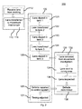
- FIG. 2 a block diagram of an illustrative embodiment of a system for a method for controlling the wetting of a lens 100 (hereinafter, the method) in accordance with the present principles is depicted.
- a lens is received in a lens reception process in block 110.
- a lens enters the method 100 when it is received from molding in block 112.
- lenses are molded in a heated, injection molding environment, and retain some residual heat after being removed from the mold.
- the lens will be removed from the mold, or de-molded, in a clean room environment, where particulate matter may be closely controlled.
- the lens may be held for some time to allow for cooling and final hardening of the plastic resins comprising the lens. Additionally, this hold time may be varied to take advantage of the residual heat in the lens, where coatings may be applied more effectively to a warmer or cooler lens surface.
- the lens may also retain a static charge generated during the molding process in addition to residual heat from the molding process.
- the aforementioned hold times may, in particularly useful embodiments, comprise part of the wetting profile for a lens, and may be specific to each lens profile, lens series, sub-part of a lens series, or the like.
- a primer very shortly after demolding.
- polycarbonate lenses begin absorbing moisture.
- primers perform better with a dryer lens, it is advantageous to prime those lenses quickly. Better adhesion allows the primer concentration to be lowered, that is, more dilute. Dilute primers are easier to work with and provide better coating results. Lower primer concentrations may also reduce potential contamination sources.
- reducing the time to reach the primer improves cycle time.
- a lens would then be transferred to a movement mechanism in block 114.
- One useful embodiment of this transfer may include one or more mechanical arms, or the like, holding, hanging or gripping a purpose built lens holder and using the lens holder to maneuver the lens.
- the lens holder may advantageously be an integrally molded plastic sprue or cold runner formed during the lens molding process.
- a plurality of lenses may be manually placed on a movement mechanism by an operator.
- any of the transferring steps may include actions designed to regulate the lens temperature, drying time of coatings, submersion and withdrawal speed of the lenses from the dipping tanks, submersion time of lenses in the tanks, and the like.
- lenses may be held during the transfer to the movement mechanism, in block 114, for such a time as to allow the lenses to cool to an advantageous temperature.
- the lenses may be held at an optimum temperature while preceding lenses are processed through the lens coating system.
- the lens may then be passed into the coating process in block 120.
- the lens Initially in the coating control block 120, the lens would be dipped into a first tank in block 121.
- the first tank may contain a cleaning solution.
- the first tank may contain a primer, advantageously in liquid form, into which the lens is dipped in block 121.
- the first tank contains a first lens coating, or the like, used to prepare the lens surface for coating.
- any static charge or residual heat retained by the lens after the molding process may be dissipated in the first bath by appropriately choosing the solution and temperature.
- the lens would then be transferred to a second tank in block 122, dipped in the second tank in block 123, transferred to a third tank in block 124, and dipped in the third tank in block 125. It should be understood that the number and order of the tanks are for illustrative purposes, and that skilled artisans will recognize that a greater or lesser number of dipping tanks may be needed for a particular coating process.
- the second tank may contain a coating to be applied to a lens.
- the lens coating may be a tint, scratch resistant coating, antireflective coating, filter coating, or any other useful coating or bath.
- the third tank may contain a solvent or other bath for finishing the coating applied in any of the previous tanks.
- the tank may contain a solvent for diluting or removing excess coating, and may be used to modify any coating previously applied.
- the third tank may include a fixative or sealer for the coatings previously applied.
- lenses may be dipped into the third tank containing a varnish or sealer that may act as a scratch resistant coating over any previously applied tint or filter coating.
- the lenses may be held for a time to facilitate coating runoff and drying between coating steps. Furthermore, the transfer between coating tanks may be accomplished simply by moving the lens via a single manipulator to the appropriate coating tank, or the lens may be transferred to a separate manipulator associated with a particular coating tank.
- the lens then enters the curing and inspection process in block 130.
- the lens is removed from the movement mechanism in block 132, and sent to the curing area in block 134.
- a manipulator may place the lens directly onto a rack for final curing, or place the lens on a separate mechanism for transport to a curing area.
- another useful embodiment may include a user manually removing the lens from the movement mechanism and placing the lens in a curing area.
- the lens will be held for curing in an area with a high degree of cleanliness, e.g. a clean room environment or the like having little airborne particulate matter that may adhere to the coatings prior to curing, which may damage the finished coating.
- a high degree of cleanliness e.g. a clean room environment or the like having little airborne particulate matter that may adhere to the coatings prior to curing, which may damage the finished coating.
- the lens when the lens is sent to the curing area in block 134, the lens may be held in the curing area for a time sufficient for any previously applied coatings to dry to an acceptable level.
- the lens is then inspected in block 136.
- the inspection process is automated, with an inspection module capable of detecting and classifying a range of defects.
- another useful embodiment may include the inspection process having a user inspecting the finished lens to determine if any defects have occurred in the coating process.
- the lens inspection of block 136 may include inspection of the lens for defects stemming not just from the coating process, but from any part of the lens forming and coating process.
- the lens inspection of block 136 may include determining whether any defects are due to the molding process, the handling process the coating process, the curing process, or the like.
- any defects are determined in block 138. Determining defects in block 136 may include determining which, if any, defects are attributable to the coating process, and which are attributable to factors or steps of the overall process unrelated to the coating process. Any defects attributed to the coating system are then reported to the control system in block 126 for consideration during succeeding lens coating steps.
- the timing of the coating process in block 120 may then be adjusted in block 127.
- the timing scheme used in the coating process may be modified to accommodate for or correct any defects that have occurred.
- the timing adjustments in block 127 may be adjustments to any controllable parameter of the method of controlling the dip coating of a lens 100.
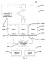
- the system 200 may include at least one automated wetting mechanism module 210, which itself may be comprised of a wetting mechanism control system module 214 and at least one manipulator module 212.
- the manipulator modules 212 may be configured to accept a lens arrangement where a plurality of lenses are attached to a single sprue, integrally molded hanger tab, lens holder, other lens handling apparatus, any of which may be integrally molded to the lenses, or separate and reusable for multiple passes through the system 200.
- the manipulator modules 212 may be configured to accept an integrally molded lens hanger that is dimensioned to permit the advantageous handling of the cold runner with attached lenses without interfering with the lenses themselves.
- the manipulator modules 212 may hold one lens throughout the coating process, with a single manipulator 212 dipping the lens in each tank 222a-222c, and transferring lenses between tanks, before moving the lens to the curing system module 236.
- multiple manipulators 212 may be independently acting on multiple lenses, respectively dip coating and transferring lenses as needed. Skilled artisans will recognize that the additional manipulators 212 may be added to the system 200 with little change to the timing characteristics of the lenses as they are being processed. Additionally, with multiple manipulators 212 in use at any given time, and each manipulator 212 manipulating a lens through the entire coating process, additional manipulators 212 may advantageously and easily be included in the system 200 for increased throughput volume.
- each tank 222a-222c may have one or more manipulators 212 associated with the tank, where each lens is transferred between the dipping manipulators 212 for each dipping step.
- each dipping tank 222a-222c may have one or more dipping manipulators that only dip lenses in the particular dipping tank 222a-222c before passing the lens to another manipulator associated with another dipping tank 222a-222c.
- the movement mechanism control system module 214 may be electrically connected to the manipulators 212, and may be configured to control the speed that the manipulator modules 212 submerge and withdraw a lens from any of the dipping tanks 222a-222c, the hold time between dipping tanks, and the like.
- the system 200 may further include a tank module 220, which may, in turn, be comprised of one or more dipping tanks 222a-222c, and one or more tank sensor/control modules 224a-224c associated with each dipping tank 222a-222c.
- the dipping tanks 222a-222c may hold liquids useful in the coating of lenses such as tints, scratch resistant coatings, primers, cleaning agents, solvents, neutralizing solutions, and the like.
- the dipping tank module 220 may be comprised of three dipping tanks, 222a-222c, where the first dipping tank holds a liquid lens coating primer, a second dipping tank 222b holds a lens coating solution, and a third dipping tank 222c holds a solvent.
- the manipulator 212 receives a lens, and dips the lens in the first tank 222a at a variable speed, holds the lens fully or partially submerged in the liquid contained in the dipping tanks for a variable time, and withdraws the lens from the dipping tank at a variable speed. Additionally, the manipulator 212 may hold the lens after removal from a tank and prior to dipping in another tank. In one useful embodiment, this hold time will permit any excess coating to run off and allow for a specified drying time. The manipulator 212 may then dip a lens into subsequent tanks 222b-222c, again varying the speed of submersion, submersion time, speed of withdrawal, and hold time between tanks.
- a lens with a variable tint e.g., a tint lighter at the bottom than at the top
- a coating tank 222a-222c holding a tint coating.
- the tint will accrete in heavier amounts on the portion of the lens dipped into the tank longer, resulting in a heavier tint coating.
- the result would be a darker tint at the part of the lens first dipped into the dipping tank 222a-222c, and a lighter tint on the part of the lens in the tint solution for less time.
- Each dipping tank 222a-222c may also have a sensor and control module 224a-224c associated with it.
- the sensor and control modules 224a-224c may be configured to measure the characteristics of an associated dipping tank 222a-222c, and may further be configured to modify or control such characteristics.
- the sensor and control modules 224a-224c may be configured to monitor and regulate the temperature, fluid levels, fluid circulation, solution concentrations, and the like, of the liquids contained in the dipping tanks 222a-222c.
- the sensor and control unit modules 224a-224c are not merely limited to monitoring and regulating the exemplified conditions, as any condition of the dipping tanks 222a-222c or the contents thereof may be monitored, regulated and adjusted. Furthermore, the sensor and control modules 224a-224c may be configured to automatically manage one or more conditions of the dipping tanks 222a-222c, or the contents thereof, automatically.
- the system 200 may further include a defect management and correction module 230, which may be comprised of a master control and tracking module, 232, an inspection system module 234, and a curing system module 236.
- the master control and tracking module 232 may be communicatively connected to the wetting control mechanism 214, the tank sensor and control modules 224a-224c, the inspection system 234 and the curing system module 236.
- the inspection system 234 and the curing system module 236 may have each an automated conveyance system for moving lenses.
- the manipulator 212 may deposit a lens onto a moving conveyor belt, or hand the lens off to another manipulator for curing and subsequent inspection.
- the manipulator 212 may, after wetting or submerging a lens in each dipping tank 222a-222c, move the lens into the curing system module 236, where it is held while curing, and then into the inspection system 234 for inspection.
- the curing system module 236 may be configured to handle lenses while the coating on the lenses hardens sufficiently for handling, as discussed above for blocks 132 and 134.
- the inspection system module 234 may be configured to handle inspection of lenses that have completed the coating process in an automated fashion, to receive input from other inspection devices, or from a user manually inspecting lenses and reporting any defects.
- the master control and tracking module may have a plurality of wetting profiles, where each wetting profile is comprised of data regarding the timing scheme for coating a particular lens.
- the wetting profile may include data related to the speed of submersion and withdrawal of a lens into each particular dipping tank 222a-222c, the submersion hold time for a lens in each dipping tank 222a-222c, the hold time between lens submersions in each dipping tank 222a-222c, optimum environmental factors such as temperature and dipping tank 222a-222c solution concentrations, optimum curing times, desirable finished lens characteristics, and the like.
- the master control and tracking module 232 uses the wetting profile to control the automated wetting mechanism module 210 to conform the manipulator 212 actions to the parameters of the wetting profile. Furthermore, the master control and tracking module 232 may use the wetting profile to control other aspects of the system that may include, but are not limited to, the temperature of liquids contained in the dipping tanks 222a-222c controlled via the tank sensor and control modules 224a-224c, the environmental conditions of the curing system module 236, environmental conditions of the system 200 in general, and the like.
- the master control and tracking module 232 may then use the data collected by the inspection system 234 to identify defects related to, and generated by the wetting system 200.
- the master control and tracking module may then retrieve data indicating the corrective measures to be taken to correct any defects, or any possible defects, and apply those corrective measures to the appropriate elements of the system 200.
- the master control and tracking module 232 may also be configured to implement one or more corrective measures to eliminate a particular discovered defect, and may monitor the lenses to which the corrective measure was applied to verify that the corrective measure completely or correctly eliminated the defect.
- implementing the corrective measures may include modifying an element of the wetting profile to eliminate or prevent defects.
- the master control and tracking module 232 may roll back, or reverse, the applied corrective measure and apply separate corrective measures.
- the master control and tracking module 232 may thus hold multiple data on defects in memory and apply the appropriate corrective measures serially to eliminate one or more defects. Such application and verification of correction measures may be applied iteratively, and the results records or analyzed to generate new corrective measures or other useful data.
- the master control and tracking module 232 may be configured to update or control the wetting control mechanism module 214, the dipping tank sensor and control modules 224a-224c, and the curing system module 236.
- the master control and tracking module 232 may correlate information communicated from the inspection system regarding defects in lenses to the time parameters used during the wetting and curing process. In one preferred embodiment, such correlations made by the master control and tracking program module 232 may be used to determine if defects are out of tolerance, or to predict if defects, while in tolerance, are increasing in frequency or magnitude as an indication of falling out of tolerance at a future point.
- the master control and tracking module 232 may have a plurality of definitions of possible types of defects, and a set of instructions for correcting or preventing defects, where each instruction is correlated to one or more defect definitions, and where the instructions are executable when a defect is detected. In this fashion, the master control and tracking module 232 may control the speed of submersion and withdrawal, the hold times between submersions, the total submersion times, the characteristics of the dipping tanks 222a-222c, the environmental characteristics of the curing system module 236 and the like.
- the master control and tracking module 232 may also advantageously update the wetting profile when the inspection system module 234 reports defects to the master control and tracking module 232, or the master control and tracking module 232 may deviate from the wetting profile based on defects and environmental changes occurring in the system 200 based on the nature of the defect.
- the inspection system module 234 may detect that lenses coming through the system 200 have an increasingly thick protective coating. Even if the lenses being inspected at the time have a tint coating that falls within an acceptable thickness range, the master control and tracking module 232 may determine that the last several lenses have had an increasingly thick tint coating, and adjust the wetting profile properties related to the tint coating thickness to prevent further defect from occurring. Specifically, in the instance of a protective coating, the master control and tracking module 232 may cause the wetting control mechanism 214, and subsequently, the manipulator 212, to hold succeeding lenses submerged in the coating for a shorter time period.
- the master control and tracking module 232 may increase the time a lens stays submerged in a solvent bath, which strips off part of the coating/primer, deceasing the coating thickness or making the primer layer more even.
- the master control and tracking module 232 may also instruct the tank sensor and control unit 224b associated with the coating tank 222b to raise or lower the temperature of the dipping tank 222b holding the coating solution, lowering the viscosity or adherent properties of the solution, and causing the coating to form a thinner layer on the lens.
- any other defects may be corrected by manipulating the timing and environmental conditions for each of the steps in the process in a like manner.
- coating systems used manual or semi-automatic controls to vary vertical dipcoating speed. For example, to increase the dipping or withdrawal speed, the vertical speed of the arm would be changed from 3 cm/sec. to 4 cm/sec. As explained above in connection with Fig. 1c , a constant arm speed results in a varying liquid-lens interface speed.
- the present system utilizes a varying arm speed to obtain a generally constant liquid-lens interface speed. Since the system is already based on different speeds for different lens sections, a coating imperfection on section 84B can be corrected without altering the wetting profile for the other sections of the lens.
- the arm speed becomes slaved to the lens surface slope and liquid-lens interface speed.
- the incremental speed control allows sections of the lens and coatings to be adjusted independently of other sections. This system reduces the likelihood of having new unrelated defects arise in response to a dip speed change.
- the master control and tracking module 232 may advantageously execute a new wetting profile in response to a change in lenses, lens families, lens geometries, base curves or range of base curves that are passing through the system 200.
- the wetting profile may have a specific incremental exposure profile specific to different lenses, different lens features, different lens geometries, different base curves and/or different ranges of base curves.
- the master control and tracking module 232 may initiate a change in the wetting profile in response to a signal from other elements of the system 200, from a user, or from any other source, that the lenses entering the system 200 have changed.
- the master control and tracking module 232 may modify or change the wetting profile in response to a different lens signal, a different lens feature signal, a different lens geometry signal, a different base curve signal, or a signal indicating a change in the range of base curves.
- the master control and tracking module 232 may be configured to notify an outside system, user, or other connected module that defects not related to the coating and curing process are occurring, which would allow correction of the defects in other portions of the lens making process.
- the inspection system module 234 may communication to the master control and tracking module 232 the nature of the defect, wherein the master control and tracking module 232 may determine that the cracks in the lens are a physical defect unrelated to the coating and curing process.
- the master control and tracking module 232 may then notify the lens production line that physical defects are being produced in the lenses.
- the master control and tracking module 232 may also track each lens as it makes it way thought the system 200. The time spent processing the lens through various tanks, transferring and holding between tanks, and curing the lens coating is such that new lenses are already in process before one lens has made its way though the entire system 200. In such a case, any adjustments made to correct current or predicted defects will not be verifiable immediately. In one useful embodiment, the master control and tracking module 232 may track lenses as they are processed through the system 200, and may correlate any changes made to the timing or environment of the system parameters to the defects in the lenses, or lack thereof, for which the changes were initiated.
- the master control and tracking module 232 may track that the next lens entering the system 200 is being processed with an altered timing scheme. Therefore, when the lens processed with the alternate timing scheme is inspected, the master control and tracking module 232 may determine whether the timing changes made for that lens were effective in correcting the tint thickness. In this manner, the master control and tracking module may, over time, be able to gather statistics to correlate the corrective actions to the correction of the defect, increasing the accuracy of the corrective actions associated with each defect type.
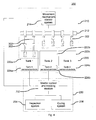
- the movement mechanism 212 may be a conveyer style mechanism, and may have multiple manipulators 302 configured to each hold a single lens element for all or most of the steps through the process. Additionally, each manipulator 302 may be configured to manually extend to dip a lens into one or more dipping tanks 222a-222c. In this useful embodiment, the movement mechanism 212 may advance the manipulators 302 to place each manipulator over a dipping tank 222a-222c so that each manipulator 302 may independently dip an associated lens into a particular dipping tank 222a-222c.
- FIG. 5 is block diagram of another alternative illustrative embodiment of an automated wetting system according to the present principles.
- each lens manipulator 302 may be of fixed length, and attached to a conveyor style movement mechanism 212.
- Each tank 222a-222c may be attached to a tank jack 402 that raises and lowers each full tank 222a-222c, to immerse each lens on a manipulator 302.
- the tank is moved by the tank jack 402 to wet the lens in the liquid.
- either the lens or the tank may be moved to place the lens within the confines of a tank 222a-222c, as shown of Figs 4 and 5 .
- the tanks 222a-222c may be held empty while the lens is moved into the tank 222a-222c, and the tank 222a-222c subsequently flooded with a desired liquid to submerge the lens.
- the tanks 222a-222c may be drained after the lens within the tank has been submerged in a liquid for the desired time period.
- the flooding and draining of the tank may be controlled by each tank's associated tank sensors and controls 224a-224c to coat the lens as dictated by each lens' wetting profile.
Landscapes
- Engineering & Computer Science (AREA)
- Health & Medical Sciences (AREA)
- Manufacturing & Machinery (AREA)
- Ophthalmology & Optometry (AREA)
- Mechanical Engineering (AREA)
- Surface Treatment Of Optical Elements (AREA)
- Application Of Or Painting With Fluid Materials (AREA)
- Eyeglasses (AREA)
- Coating Apparatus (AREA)
Claims (16)
- Appareil servant à humecter et à revêtir des lentilles ophtalmiques (32), comportant :au moins un réservoir (222a - 222c) adapté pour contenir une solution liquide ;un système de manipulation (212) permettant de déplacer séquentiellement une lentille (32) et la solution liquide l'une par rapport à l'autre ; etun module de commande principal (232) couplé audit système de manipulation (212), et configuré à des fins de commande de l'exécution de l'humectation de la lentille (32) en fonction d'un profil d'humectation ; caractérisé en ce queledit profil d'humectation comprend des données stockées pour la solution liquide dudit au moins un réservoir (222a - 222c), comportant des instructions en provenance du module de commande principal pour commander le système de manipulation afin d'exécuter:une période d'attente avant la submersion ;un profil de vitesse/d'accélération de submersion ;une durée d'immersion ; etun profil de vitesse/d'accélération de retrait,et en ce que le module de commande principal (232) est configurée à des fins de modification d'au moins un élément du profil d'humectation, y compris l'une parmi une vitesse de submersion non linéaire, et une vitesse de retrait non linéaire pour une section de lentille discrète,dans lequel ledit profil d'humectation comporte des instructions permettant de commander l'interface de la lentille et de la solution liquide pour réduire les imperfections au niveau du revêtement de la lentille.
- Appareil selon la revendication 1, dans lequel ladite au moins une solution liquide est sélectionnée dans le groupe constitué par une solution nettoyante, une solution primaire, une solution de rinçage, une solution de revêtement, et une solution de neutralisation.
- Appareil selon la revendication 1, comportant par ailleurs un système d'inspection (234) permettant de fournir des données d'inspection de lentille.
- Appareil selon la revendication 3, dans lequel le module de commande principal (232) est configuré à des fins de contrôle des données d'inspection en vue d'identifier des défauts d'épaisseur du revêtement se rapportant au profil d'humectation.
- Appareil selon la revendication 4, dans lequel le module de commande principal (232) est par ailleurs configuré à des fins d'extraction de données de correction correspondant aux défauts identifiés, et à des fins de modification du profil d'humectation en fonction des données de correction ;
à des fins de suivi des lentilles optiques en fonction du profil d'humectation modifié et à des fins d'évaluation pour savoir si les modifications apportées au profil d'humectation ont corrigé les défauts identifiés ;
à des fins de stockage d'informations concernant la précision des modifications apportées au profil d'humectation par rapport à la correction des défauts identifiés ; et
à des fins d'incorporation des informations stockées dans des modifications successives apportées au profil d'humectation. - Appareil selon l'une quelconque des revendications précédentes, comportant au moins deux réservoirs (222a - 222c), un différent profil d'humectation étant utilisé pour chaque réservoir.
- Appareil selon l'une quelconque des revendications précédentes, dans lequel le système de manipulation (212) modifie le niveau de solution liquide en fonction de la pente verticale incrémentale de la surface de la lentille par rapport à la surface de la solution, et en fonction de la longueur de l'arc en travers de la surface de la lentille pour fournir une vitesse d'interface liquide-lentille plus constante.
- Appareil selon l'une quelconque des revendications précédentes, dans lequel le système de manipulation (212) est configuré à des fins de retenue parmi la retenue de la lentille (32) dans une position fixe, et dans lequel ledit au moins un réservoir (222a - 222c) est configuré à des fins de maintien d'un niveau constant de solution liquide, et à des fins de déplacement du réservoir (222a - 222c) pour submerger la lentille (32) en fonction du profil d'humectation ; et la retenue d'une lentille (32) dans une position fixe par rapport à la position du réservoir (222a - 222c), et le réservoir de trempage (222a - 222c) est configuré à des fins de remplissage par une solution liquide pour submerger la lentille en fonction du profil d'humectation.
- Appareil selon la revendication 1, comportant par ailleurs au moins deux solutions liquides, dans lequel le système de manipulation est par ailleurs configuré à des fins de déplacement de la lentille entre des solutions liquides ; et dans lequel le profil d'humectation est basé sur au moins l'une dans un groupe constitué par une lentille, une caractéristique de lentille, une géométrie de lentille, une courbe de base, et une plage de courbes de base.
- Procédé de submersion de lentilles optiques (32) dans une solution liquide, le procédé comportant les étapes consistant à :placer une lentille (32) dans un système de manipulation (212) ;commander l'exécution d'au moins un profil d'humectation par un module de commande principal (232) ; et humecter la lentille (32) dans au moins une solution liquide par le système de manipulation de lentille (212) en fonction dudit au moins un profil d'humectation caractérisé par ledit profil d'humectation comportant pour la solution liquide dudit au moins un réservoir (222a - 222c)une période d'attente avant la submersion ;un profil de vitesse/d'accélération de submersion ;une durée d'immersion ; etun profil de vitesse/d'accélération de retrait ; et comportant par ailleursle module de commande principal (232) qui modifie au moins un élément du profil d'humectation, y compris l'une parmi une vitesse de submersion non linéaire, et une vitesse de retrait non linéaire pour une section de lentille discrète, etle profil d'humectation étant basé sur la pente verticale incrémentale de la surface de la lentille par rapport à la surface de la solution liquide.
- Procédé selon la revendication 10, dans lequel le procédé comporte par ailleurs les étapes consistant à générer des données d'inspection de lentille en inspectant la lentille (32) ; et à contrôler les données d'inspection de lentille à la recherche de défauts d'épaisseur du revêtement se rapportant au profil d'humectation.
- Procédé selon la revendication 11, dans lequel le procédé comporte par ailleurs les étapes consistant à extraire des données de correction en fonction des défauts identifiés, et à modifier le profil d'humectation en fonction des données de correction ; à suivre les lentilles (32) humectées en fonction d'un profil d'humectation modifié, et à évaluer l'efficacité de la correction des défauts identifiés par les modifications apportées au profil d'humectation ; à stocker des informations concernant l'efficacité des modifications apportées au profil d'humectation pour la correction des défauts identifiés ; et à appliquer les informations stockées à des exécutions successives du profil d'humectation.
- Procédé selon la revendication 11, dans lequel le procédé comporte par ailleurs les étapes consistant à contrôler les données d'inspection de lentille à la recherche de défauts de moulage, et à extraire des données de correction en fonction des défauts identifiés, et à arrêter l'exécution du profil d'humectation jusqu'à ce que les défauts de moulage soient corrigés.
- Procédé selon la revendication 10, dans lequel ladite étape d'humectation comporte l'un parmi
un mouvement non linéaire de la lentille (32) dans ladite au moins une solution liquide en fonction dudit au moins un profil d'humectation, dans lequel ladite au moins une solution liquide est fixe ;
une retenue d'une lentille (32) de manière fixe et un mouvement non linéaire d'un réservoir (222a - 222c) contenant une quantité prédéterminée de solution liquide pour submerger la lentille (32) en fonction du profil d'humectation ; et
une retenue d'une lentille (32) et d'un réservoir (222a - 222c) de la solution liquide de manière fixe, et une inondation non linéaire d'une solution liquide pour submerger la lentille (32) en fonction du profil d'humectation. - Procédé selon la revendication 10, dans lequel ladite étape d'humectation modifie le niveau de solution liquide soit en fonction d'une pente verticale incrémentale de la surface de la lentille par rapport à la surface du niveau de solution liquide, soit en fonction de la longueur de l'arc en travers de la surface de la lentille.
- Procédé selon la revendication 10, dans lequel la lentille retient de la chaleur résiduelle en provenance du moule lorsqu'elle entre tout d'abord en contact avec la solution liquide ; et dans lequel la lentille entre tout d'abord en contact avec une solution liquide contenant une solution primaire, au cours d'une durée pendant laquelle la lentille est encore sèche en provenance du moule.
Applications Claiming Priority (1)
| Application Number | Priority Date | Filing Date | Title |
|---|---|---|---|
| US11/880,751 US8153035B2 (en) | 2007-07-24 | 2007-07-24 | Programmable wetting controller |
Publications (3)
| Publication Number | Publication Date |
|---|---|
| EP2018954A2 EP2018954A2 (fr) | 2009-01-28 |
| EP2018954A3 EP2018954A3 (fr) | 2010-06-16 |
| EP2018954B1 true EP2018954B1 (fr) | 2014-11-12 |
Family
ID=40040106
Family Applications (1)
| Application Number | Title | Priority Date | Filing Date |
|---|---|---|---|
| EP08104614.6A Active EP2018954B1 (fr) | 2007-07-24 | 2008-07-02 | Appareil et procédé pour humecter des lentilles de contact |
Country Status (7)
| Country | Link |
|---|---|
| US (1) | US8153035B2 (fr) |
| EP (1) | EP2018954B1 (fr) |
| CN (1) | CN101354446B (fr) |
| BR (1) | BRPI0803743B1 (fr) |
| IL (1) | IL192146A (fr) |
| MX (1) | MX2008008897A (fr) |
| TW (1) | TWI449943B (fr) |
Families Citing this family (13)
| Publication number | Priority date | Publication date | Assignee | Title |
|---|---|---|---|---|
| US8316593B2 (en) * | 2009-03-18 | 2012-11-27 | Garland Industries, Inc. | Solar roofing system |
| EP2488351B1 (fr) | 2009-10-16 | 2016-05-04 | Novartis AG | Appareil et procédé pour transporter des lentilles de contact à travers des bains de trempage |
| EP2552682B1 (fr) * | 2010-04-02 | 2015-01-14 | Essilor International (Compagnie Générale D'Optique) | Procédé de revêtement d'une lentille par trempage |
| JP5874011B2 (ja) * | 2011-01-28 | 2016-03-01 | パナソニックIpマネジメント株式会社 | 太陽電池及び太陽電池モジュール |
| US20130310195A1 (en) * | 2012-05-18 | 2013-11-21 | Nike Inc. | Method Apparatus for Producing a Golf Ball |
| WO2014092677A1 (fr) * | 2012-12-10 | 2014-06-19 | Alliance For Sustainable Engery, Llc | Cellules solaires à jonctions multiples monolithiques à tension adaptée en tandem |
| US20170271535A1 (en) * | 2014-05-19 | 2017-09-21 | Sun Chemical Corporation | A silver paste containing bismuth oxide and its use in solar cells |
| DE102017007752A1 (de) * | 2016-08-29 | 2018-03-01 | Schneider Gmbh & Co. Kg | Vorrichtung und Verfahren zum Reinigen einer Linse |
| CN109814549B (zh) * | 2018-12-29 | 2023-11-10 | 北京英视睿达科技股份有限公司 | 一种确定污染源位置的方法、装置和系统 |
| WO2022205029A1 (fr) * | 2021-03-31 | 2022-10-06 | Carl Zeiss Vision International Gmbh | Procédé de teinte ou de décoloration d'une lentille, lentille obtenue par le procédé de teinte ou de décoration d'une lentille, lentille comprenant une teinte ou décoloration, support de lentille et dispositif de teinte pour teinter une lentille |
| BR112023023167A2 (pt) * | 2021-05-07 | 2024-01-30 | Essilor Int | Método de revestimento de lentes com lenslets com controle melhorado no deslocamento de potência |
| EP4105010B1 (fr) * | 2021-06-18 | 2024-08-07 | Essilor International | Procédé de revêtement de lentilles avec des microlentilles ayant un contrôle amélioré du changement de puissance |
| CN117270088A (zh) * | 2023-09-27 | 2023-12-22 | 歌尔光学科技有限公司 | 镜片浸涂控制方法、装置、电子设备及可读存储介质 |
Family Cites Families (43)
| Publication number | Priority date | Publication date | Assignee | Title |
|---|---|---|---|---|
| LU46834A1 (fr) | 1964-08-26 | 1966-02-28 | ||
| US3956540A (en) | 1973-09-10 | 1976-05-11 | Omnitech Inc. | Method of coating articles |
| US4084021A (en) | 1974-10-08 | 1978-04-11 | Minnesota Mining And Manufacturing Company | Method for rendering substrates resistant to abrasion |
| JPS53140380A (en) | 1977-05-13 | 1978-12-07 | Seiko Epson Corp | Lens dyeing device |
| AU525294B2 (en) | 1979-07-09 | 1982-10-28 | Mitsubishi Rayon Company Limited | Dip coating |
| US4267208A (en) | 1979-07-30 | 1981-05-12 | Ireland Jack W | Coating of optical lens for blocking purposes |
| US4245991A (en) | 1979-12-12 | 1981-01-20 | American Hoechst Corporation | Dip dyeing of plastic articles and the dye bath composition thereof |
| US4345546A (en) | 1981-06-15 | 1982-08-24 | Weber Hermann P | Apparatus for coating items |
| US4455322A (en) | 1981-06-15 | 1984-06-19 | Techsight Corporation | Method for coating items |
| US4438159A (en) | 1982-03-08 | 1984-03-20 | Techsight Corporation | Coating process |
| US4476162A (en) | 1982-04-30 | 1984-10-09 | Ireland Jack W | Method for coating lenses |
| JPS5913201A (ja) | 1982-07-15 | 1984-01-24 | Hitachi Ltd | 合成樹脂製レンズに反射防止膜を設ける方法 |
| CA1199762A (fr) | 1982-09-07 | 1986-01-28 | Timothy C. Sandvig | Methode pour enduire les lentilles ophtalmiques |
| US4544572A (en) | 1982-09-07 | 1985-10-01 | Minnesota Mining And Manufacturing Company | Coated ophthalmic lenses and method for coating the same |
| DE8416309U1 (de) | 1984-05-26 | 1985-03-28 | Opticproduct GmbH + Co Vertriebs KG, 6100 Darmstadt | Kompakte vorrichtung zur kontinuierlichen kratzfestbeschichtung von kunststoff-formkoerpern |
| US4710199A (en) | 1985-06-03 | 1987-12-01 | Roag (Ag) | Method of dyeing an optical article |
| US4915986A (en) | 1988-03-07 | 1990-04-10 | Elias Tariq J | Optical lens tinting machine |
| US5052337A (en) | 1988-10-31 | 1991-10-01 | Talcott Thomas D | Lens dyeing method and apparatus comprising heating element contacting dyeing tank, heat controller and sensor for dye solution temperature |
| JPH0829291B2 (ja) | 1989-08-14 | 1996-03-27 | ホーヤ株式会社 | レンズの染色方法 |
| JP3127485B2 (ja) | 1990-07-10 | 2001-01-22 | セイコーエプソン株式会社 | レンズの染色方法 |
| US5201955A (en) | 1991-03-11 | 1993-04-13 | Chika Hani E | Annular gradient optical lens tint system |
| US5164228A (en) | 1991-05-20 | 1992-11-17 | Bmc Industries, Inc. | Method of applying scratch-resistant coatings to plastic ophthalmic lenses |
| US5153027A (en) | 1991-06-10 | 1992-10-06 | Ford Motor Company | Preparation of differential thickness coatings by dip coating where the substrate is pivoted |
| US5334246A (en) | 1992-12-23 | 1994-08-02 | Xerox Corporation | Dip coat process material handling system |
| US5514214A (en) | 1993-09-20 | 1996-05-07 | Q2100, Inc. | Eyeglass lens and mold spin coater |
| US5718849A (en) * | 1995-09-25 | 1998-02-17 | Galic Maus Ventures | Method and apparatus for injection-compression molding & ejecting paired thermoplastic spectacle lens suited for fully automated dip hardcoating |
| US5772861A (en) | 1995-10-16 | 1998-06-30 | Viratec Thin Films, Inc. | System for evaluating thin film coatings |
| US6129042A (en) | 1996-11-08 | 2000-10-10 | Coburn Optical Industries, Inc. | Process and machine for coating ophthalmic lenses |
| US5820673A (en) | 1996-11-12 | 1998-10-13 | Sentilles; J. Bruce | Apparatus for applying coatings to lenses and curing the coatings |
| US6039806A (en) | 1998-04-20 | 2000-03-21 | E-Tek Dynamics, Inc. | Precision thickness optical coating system and method of operation thereof |
| EP1077797B1 (fr) | 1998-05-15 | 2003-03-26 | Great Lakes Chemical Corporation | Lentilles ophtalmiques |
| US6355104B1 (en) | 1998-11-20 | 2002-03-12 | Louis S. Polster | Article treating apparatus and method and control system therefor |
| US6296707B1 (en) | 1999-03-17 | 2001-10-02 | Gerber Coburn Optical, Inc. | Apparatus for coating a surface of one or more lenses |
| JP2000288891A (ja) | 1999-04-01 | 2000-10-17 | Seiko Epson Corp | 眼鏡用レンズの製造方法及びレンズ加工装置 |
| US6270850B1 (en) | 1999-06-10 | 2001-08-07 | Xerox Corporation | Method to improve dip coating |
| US6387441B1 (en) | 2000-09-06 | 2002-05-14 | Optima, Inc. | Optical lens coating apparatus and method |
| US6858248B2 (en) | 2001-05-30 | 2005-02-22 | Novartis Ag | Method for applying a coating to a medical device |
| US7025457B2 (en) | 2002-07-31 | 2006-04-11 | Vision-Ease Lens | Dip coating process for optical elements |
| US20040222540A1 (en) | 2003-05-06 | 2004-11-11 | Weymouth Russell F. | In-line lens manufacturing |
| US6972136B2 (en) | 2003-05-23 | 2005-12-06 | Optima, Inc. | Ultra low residual reflection, low stress lens coating and vacuum deposition method for making the same |
| US6991827B2 (en) | 2003-11-07 | 2006-01-31 | Essilor International Compagnie Generale D'optique | Apparatus and method for dip coating lenses |
| US7727581B2 (en) | 2004-03-17 | 2010-06-01 | Essilor International Compagnie Generale D' Optique | Process for applying a coating on an optical lens face and implementation system |
| MY161660A (en) | 2005-05-04 | 2017-04-28 | Novartis Ag | Automated inspection of colored contact lenses |
-
2007
- 2007-07-24 US US11/880,751 patent/US8153035B2/en active Active
-
2008
- 2008-06-12 IL IL192146A patent/IL192146A/en active IP Right Grant
- 2008-06-18 TW TW097122646A patent/TWI449943B/zh active
- 2008-07-02 EP EP08104614.6A patent/EP2018954B1/fr active Active
- 2008-07-09 MX MX2008008897A patent/MX2008008897A/es active IP Right Grant
- 2008-07-21 BR BRPI0803743-4A patent/BRPI0803743B1/pt active IP Right Grant
- 2008-07-23 CN CN2008101337835A patent/CN101354446B/zh active Active
Also Published As
| Publication number | Publication date |
|---|---|
| TW200912364A (en) | 2009-03-16 |
| US20090026640A1 (en) | 2009-01-29 |
| MX2008008897A (es) | 2009-03-04 |
| CN101354446A (zh) | 2009-01-28 |
| BRPI0803743B1 (pt) | 2019-05-14 |
| TWI449943B (zh) | 2014-08-21 |
| EP2018954A2 (fr) | 2009-01-28 |
| US8153035B2 (en) | 2012-04-10 |
| IL192146A0 (en) | 2009-02-11 |
| HK1129245A1 (en) | 2009-11-20 |
| CN101354446B (zh) | 2012-07-04 |
| EP2018954A3 (fr) | 2010-06-16 |
| BRPI0803743A2 (pt) | 2009-12-08 |
| IL192146A (en) | 2012-06-28 |
Similar Documents
| Publication | Publication Date | Title |
|---|---|---|
| US8153035B2 (en) | Programmable wetting controller | |
| JP5023078B2 (ja) | コート層を有するレンズの製造方法 | |
| JP2016540625A (ja) | 光学基材に複数コーティングを塗布するためのスピンコーター | |
| JP6936874B2 (ja) | 光学材料用モノマーの自動注入方法及び自動注入装置 | |
| KR102161090B1 (ko) | 기판 코팅장치 및 방법 | |
| US20020127347A1 (en) | Method and apparatus for producing coated plate | |
| US6207337B1 (en) | Immersion coating system | |
| HK1129245B (en) | Programmable wetting controller | |
| US7025457B2 (en) | Dip coating process for optical elements | |
| CN106415805B (zh) | 用于确定衬底上的涂层的屏障效应的方法和装置 | |
| US20060284326A1 (en) | In-line lens manufacturing | |
| US20040222538A1 (en) | In-line lens manufacturing | |
| KR20240006539A (ko) | 굴절력 변화에 대한 제어가 개선된 렌즈렛을 갖는 렌즈를 코팅하기 위한 방법 | |
| KR20080083443A (ko) | 마이크로파를 이용한 안경렌즈의 건조장치 | |
| US6183678B1 (en) | Method of processing a molded plastic glazing panel | |
| JPH05341237A (ja) | 眼鏡用プラスチックレンズの製造におけるハードコーティング方法およびその装置 | |
| JP2003154304A (ja) | 塗布材塗布方法、被塗布基材、被塗布基材の製造方法、及び被塗布基材を含む塗布材塗布装置 | |
| CN116546864A (zh) | 一种钙钛矿薄膜制备方法和钙钛矿薄膜制备装置 | |
| CN118988597A (zh) | Ps版涂敷生产线体的自动闭环控制方法及系统 | |
| KR20240022469A (ko) | 도수 변이 제어가 개선된 렌즈릿을 갖는 렌즈를 코팅하는 방법 | |
| CN118578648A (zh) | 一种基膜涂层用预涂膜双向拉伸工艺 | |
| JP2005103426A (ja) | 板状塗工物の製造方法及び塗布装置 | |
| JPH0519121B2 (fr) | ||
| JPH03157662A (ja) | ドラム塗布方法 |
Legal Events
| Date | Code | Title | Description |
|---|---|---|---|
| PUAI | Public reference made under article 153(3) epc to a published international application that has entered the european phase |
Free format text: ORIGINAL CODE: 0009012 |
|
| AK | Designated contracting states |
Kind code of ref document: A2 Designated state(s): AT BE BG CH CY CZ DE DK EE ES FI FR GB GR HR HU IE IS IT LI LT LU LV MC MT NL NO PL PT RO SE SI SK TR |
|
| AX | Request for extension of the european patent |
Extension state: AL BA MK RS |
|
| PUAL | Search report despatched |
Free format text: ORIGINAL CODE: 0009013 |
|
| AK | Designated contracting states |
Kind code of ref document: A3 Designated state(s): AT BE BG CH CY CZ DE DK EE ES FI FR GB GR HR HU IE IS IT LI LT LU LV MC MT NL NO PL PT RO SE SI SK TR |
|
| AX | Request for extension of the european patent |
Extension state: AL BA MK RS |
|
| 17P | Request for examination filed |
Effective date: 20101202 |
|
| AKX | Designation fees paid |
Designated state(s): AT BE BG CH CY CZ DE DK EE ES FI FR GB GR HR HU IE IS IT LI LT LU LV MC MT NL NO PL PT RO SE SI SK TR |
|
| 17Q | First examination report despatched |
Effective date: 20130405 |
|
| GRAP | Despatch of communication of intention to grant a patent |
Free format text: ORIGINAL CODE: EPIDOSNIGR1 |
|
| INTG | Intention to grant announced |
Effective date: 20140519 |
|
| GRAS | Grant fee paid |
Free format text: ORIGINAL CODE: EPIDOSNIGR3 |
|
| GRAP | Despatch of communication of intention to grant a patent |
Free format text: ORIGINAL CODE: EPIDOSNIGR1 |
|
| GRAA | (expected) grant |
Free format text: ORIGINAL CODE: 0009210 |
|
| INTG | Intention to grant announced |
Effective date: 20140925 |
|
| AK | Designated contracting states |
Kind code of ref document: B1 Designated state(s): AT BE BG CH CY CZ DE DK EE ES FI FR GB GR HR HU IE IS IT LI LT LU LV MC MT NL NO PL PT RO SE SI SK TR |
|
| REG | Reference to a national code |
Ref country code: GB Ref legal event code: FG4D |
|
| REG | Reference to a national code |
Ref country code: CH Ref legal event code: EP |
|
| REG | Reference to a national code |
Ref country code: AT Ref legal event code: REF Ref document number: 695476 Country of ref document: AT Kind code of ref document: T Effective date: 20141115 |
|
| REG | Reference to a national code |
Ref country code: IE Ref legal event code: FG4D |
|
| REG | Reference to a national code |
Ref country code: DE Ref legal event code: R096 Ref document number: 602008035272 Country of ref document: DE Effective date: 20141224 |
|
| RAP2 | Party data changed (patent owner data changed or rights of a patent transferred) |
Owner name: GENTEX OPTICS, INC. |
|
| REG | Reference to a national code |
Ref country code: NL Ref legal event code: VDEP Effective date: 20141112 |
|
| REG | Reference to a national code |
Ref country code: AT Ref legal event code: MK05 Ref document number: 695476 Country of ref document: AT Kind code of ref document: T Effective date: 20141112 |
|
| PG25 | Lapsed in a contracting state [announced via postgrant information from national office to epo] |
Ref country code: LT Free format text: LAPSE BECAUSE OF FAILURE TO SUBMIT A TRANSLATION OF THE DESCRIPTION OR TO PAY THE FEE WITHIN THE PRESCRIBED TIME-LIMIT Effective date: 20141112 Ref country code: NL Free format text: LAPSE BECAUSE OF FAILURE TO SUBMIT A TRANSLATION OF THE DESCRIPTION OR TO PAY THE FEE WITHIN THE PRESCRIBED TIME-LIMIT Effective date: 20141112 Ref country code: FI Free format text: LAPSE BECAUSE OF FAILURE TO SUBMIT A TRANSLATION OF THE DESCRIPTION OR TO PAY THE FEE WITHIN THE PRESCRIBED TIME-LIMIT Effective date: 20141112 Ref country code: NO Free format text: LAPSE BECAUSE OF FAILURE TO SUBMIT A TRANSLATION OF THE DESCRIPTION OR TO PAY THE FEE WITHIN THE PRESCRIBED TIME-LIMIT Effective date: 20150212 Ref country code: ES Free format text: LAPSE BECAUSE OF FAILURE TO SUBMIT A TRANSLATION OF THE DESCRIPTION OR TO PAY THE FEE WITHIN THE PRESCRIBED TIME-LIMIT Effective date: 20141112 Ref country code: IS Free format text: LAPSE BECAUSE OF FAILURE TO SUBMIT A TRANSLATION OF THE DESCRIPTION OR TO PAY THE FEE WITHIN THE PRESCRIBED TIME-LIMIT Effective date: 20150312 Ref country code: PT Free format text: LAPSE BECAUSE OF FAILURE TO SUBMIT A TRANSLATION OF THE DESCRIPTION OR TO PAY THE FEE WITHIN THE PRESCRIBED TIME-LIMIT Effective date: 20150312 |
|
| REG | Reference to a national code |
Ref country code: DE Ref legal event code: R082 Ref document number: 602008035272 Country of ref document: DE Representative=s name: VON KREISLER SELTING WERNER - PARTNERSCHAFT VO, DE |
|
| PG25 | Lapsed in a contracting state [announced via postgrant information from national office to epo] |
Ref country code: HR Free format text: LAPSE BECAUSE OF FAILURE TO SUBMIT A TRANSLATION OF THE DESCRIPTION OR TO PAY THE FEE WITHIN THE PRESCRIBED TIME-LIMIT Effective date: 20141112 Ref country code: LV Free format text: LAPSE BECAUSE OF FAILURE TO SUBMIT A TRANSLATION OF THE DESCRIPTION OR TO PAY THE FEE WITHIN THE PRESCRIBED TIME-LIMIT Effective date: 20141112 Ref country code: GR Free format text: LAPSE BECAUSE OF FAILURE TO SUBMIT A TRANSLATION OF THE DESCRIPTION OR TO PAY THE FEE WITHIN THE PRESCRIBED TIME-LIMIT Effective date: 20150213 Ref country code: AT Free format text: LAPSE BECAUSE OF FAILURE TO SUBMIT A TRANSLATION OF THE DESCRIPTION OR TO PAY THE FEE WITHIN THE PRESCRIBED TIME-LIMIT Effective date: 20141112 Ref country code: SE Free format text: LAPSE BECAUSE OF FAILURE TO SUBMIT A TRANSLATION OF THE DESCRIPTION OR TO PAY THE FEE WITHIN THE PRESCRIBED TIME-LIMIT Effective date: 20141112 Ref country code: CY Free format text: LAPSE BECAUSE OF FAILURE TO SUBMIT A TRANSLATION OF THE DESCRIPTION OR TO PAY THE FEE WITHIN THE PRESCRIBED TIME-LIMIT Effective date: 20141112 Ref country code: PL Free format text: LAPSE BECAUSE OF FAILURE TO SUBMIT A TRANSLATION OF THE DESCRIPTION OR TO PAY THE FEE WITHIN THE PRESCRIBED TIME-LIMIT Effective date: 20141112 |
|
| REG | Reference to a national code |
Ref country code: DE Ref legal event code: R082 Ref document number: 602008035272 Country of ref document: DE Representative=s name: VON KREISLER SELTING WERNER - PARTNERSCHAFT VO, DE Effective date: 20150507 Ref country code: DE Ref legal event code: R081 Ref document number: 602008035272 Country of ref document: DE Owner name: GENTEX OPTICS, INC., DUDLEY, US Free format text: FORMER OWNER: GENTEX OPTICS, INC., SIMPSON, PA., US Effective date: 20150507 Ref country code: DE Ref legal event code: R082 Ref document number: 602008035272 Country of ref document: DE Representative=s name: DOMPATENT VON KREISLER SELTING WERNER - PARTNE, DE Effective date: 20150507 |
|
| REG | Reference to a national code |
Ref country code: FR Ref legal event code: PLFP Year of fee payment: 8 |
|
| PG25 | Lapsed in a contracting state [announced via postgrant information from national office to epo] |
Ref country code: RO Free format text: LAPSE BECAUSE OF FAILURE TO SUBMIT A TRANSLATION OF THE DESCRIPTION OR TO PAY THE FEE WITHIN THE PRESCRIBED TIME-LIMIT Effective date: 20141112 Ref country code: CZ Free format text: LAPSE BECAUSE OF FAILURE TO SUBMIT A TRANSLATION OF THE DESCRIPTION OR TO PAY THE FEE WITHIN THE PRESCRIBED TIME-LIMIT Effective date: 20141112 Ref country code: SK Free format text: LAPSE BECAUSE OF FAILURE TO SUBMIT A TRANSLATION OF THE DESCRIPTION OR TO PAY THE FEE WITHIN THE PRESCRIBED TIME-LIMIT Effective date: 20141112 Ref country code: DK Free format text: LAPSE BECAUSE OF FAILURE TO SUBMIT A TRANSLATION OF THE DESCRIPTION OR TO PAY THE FEE WITHIN THE PRESCRIBED TIME-LIMIT Effective date: 20141112 Ref country code: EE Free format text: LAPSE BECAUSE OF FAILURE TO SUBMIT A TRANSLATION OF THE DESCRIPTION OR TO PAY THE FEE WITHIN THE PRESCRIBED TIME-LIMIT Effective date: 20141112 |
|
| REG | Reference to a national code |
Ref country code: DE Ref legal event code: R097 Ref document number: 602008035272 Country of ref document: DE |
|
| PLBE | No opposition filed within time limit |
Free format text: ORIGINAL CODE: 0009261 |
|
| STAA | Information on the status of an ep patent application or granted ep patent |
Free format text: STATUS: NO OPPOSITION FILED WITHIN TIME LIMIT |
|
| 26N | No opposition filed |
Effective date: 20150813 |
|
| REG | Reference to a national code |
Ref country code: FR Ref legal event code: CA Effective date: 20151013 |
|
| PG25 | Lapsed in a contracting state [announced via postgrant information from national office to epo] |
Ref country code: IT Free format text: LAPSE BECAUSE OF FAILURE TO SUBMIT A TRANSLATION OF THE DESCRIPTION OR TO PAY THE FEE WITHIN THE PRESCRIBED TIME-LIMIT Effective date: 20141112 |
|
| PG25 | Lapsed in a contracting state [announced via postgrant information from national office to epo] |
Ref country code: MC Free format text: LAPSE BECAUSE OF FAILURE TO SUBMIT A TRANSLATION OF THE DESCRIPTION OR TO PAY THE FEE WITHIN THE PRESCRIBED TIME-LIMIT Effective date: 20141112 Ref country code: SI Free format text: LAPSE BECAUSE OF FAILURE TO SUBMIT A TRANSLATION OF THE DESCRIPTION OR TO PAY THE FEE WITHIN THE PRESCRIBED TIME-LIMIT Effective date: 20141112 |
|
| REG | Reference to a national code |
Ref country code: CH Ref legal event code: PL |
|
| PG25 | Lapsed in a contracting state [announced via postgrant information from national office to epo] |
Ref country code: LU Free format text: LAPSE BECAUSE OF FAILURE TO SUBMIT A TRANSLATION OF THE DESCRIPTION OR TO PAY THE FEE WITHIN THE PRESCRIBED TIME-LIMIT Effective date: 20150702 |
|
| REG | Reference to a national code |
Ref country code: IE Ref legal event code: MM4A |
|
| PG25 | Lapsed in a contracting state [announced via postgrant information from national office to epo] |
Ref country code: LI Free format text: LAPSE BECAUSE OF NON-PAYMENT OF DUE FEES Effective date: 20150731 Ref country code: CH Free format text: LAPSE BECAUSE OF NON-PAYMENT OF DUE FEES Effective date: 20150731 |
|
| REG | Reference to a national code |
Ref country code: FR Ref legal event code: PLFP Year of fee payment: 9 |
|
| PG25 | Lapsed in a contracting state [announced via postgrant information from national office to epo] |
Ref country code: IE Free format text: LAPSE BECAUSE OF NON-PAYMENT OF DUE FEES Effective date: 20150702 |
|
| PG25 | Lapsed in a contracting state [announced via postgrant information from national office to epo] |
Ref country code: MT Free format text: LAPSE BECAUSE OF FAILURE TO SUBMIT A TRANSLATION OF THE DESCRIPTION OR TO PAY THE FEE WITHIN THE PRESCRIBED TIME-LIMIT Effective date: 20141112 |
|
| PG25 | Lapsed in a contracting state [announced via postgrant information from national office to epo] |
Ref country code: BG Free format text: LAPSE BECAUSE OF FAILURE TO SUBMIT A TRANSLATION OF THE DESCRIPTION OR TO PAY THE FEE WITHIN THE PRESCRIBED TIME-LIMIT Effective date: 20141112 Ref country code: HU Free format text: LAPSE BECAUSE OF FAILURE TO SUBMIT A TRANSLATION OF THE DESCRIPTION OR TO PAY THE FEE WITHIN THE PRESCRIBED TIME-LIMIT; INVALID AB INITIO Effective date: 20080702 |
|
| REG | Reference to a national code |
Ref country code: FR Ref legal event code: PLFP Year of fee payment: 10 |
|
| PG25 | Lapsed in a contracting state [announced via postgrant information from national office to epo] |
Ref country code: TR Free format text: LAPSE BECAUSE OF FAILURE TO SUBMIT A TRANSLATION OF THE DESCRIPTION OR TO PAY THE FEE WITHIN THE PRESCRIBED TIME-LIMIT Effective date: 20141112 |
|
| PG25 | Lapsed in a contracting state [announced via postgrant information from national office to epo] |
Ref country code: BE Free format text: LAPSE BECAUSE OF FAILURE TO SUBMIT A TRANSLATION OF THE DESCRIPTION OR TO PAY THE FEE WITHIN THE PRESCRIBED TIME-LIMIT Effective date: 20141112 |
|
| REG | Reference to a national code |
Ref country code: FR Ref legal event code: PLFP Year of fee payment: 11 |
|
| PGFP | Annual fee paid to national office [announced via postgrant information from national office to epo] |
Ref country code: DE Payment date: 20250729 Year of fee payment: 18 |
|
| PGFP | Annual fee paid to national office [announced via postgrant information from national office to epo] |
Ref country code: GB Payment date: 20250728 Year of fee payment: 18 |
|
| PGFP | Annual fee paid to national office [announced via postgrant information from national office to epo] |
Ref country code: FR Payment date: 20250725 Year of fee payment: 18 |