EP2019169B1 - Elément de revêtement de sol, grille de revêtement de sol et agencement de grilles de revêtement de sol ainsi que procédé de fabrication d'une grille de revêtement de sol - Google Patents
Elément de revêtement de sol, grille de revêtement de sol et agencement de grilles de revêtement de sol ainsi que procédé de fabrication d'une grille de revêtement de sol Download PDFInfo
- Publication number
- EP2019169B1 EP2019169B1 EP08009090.5A EP08009090A EP2019169B1 EP 2019169 B1 EP2019169 B1 EP 2019169B1 EP 08009090 A EP08009090 A EP 08009090A EP 2019169 B1 EP2019169 B1 EP 2019169B1
- Authority
- EP
- European Patent Office
- Prior art keywords
- flooring
- grid
- floor covering
- elements
- recesses
- Prior art date
- Legal status (The legal status is an assumption and is not a legal conclusion. Google has not performed a legal analysis and makes no representation as to the accuracy of the status listed.)
- Active
Links
Images


Classifications
-
- E—FIXED CONSTRUCTIONS
- E01—CONSTRUCTION OF ROADS, RAILWAYS, OR BRIDGES
- E01C—CONSTRUCTION OF, OR SURFACES FOR, ROADS, SPORTS GROUNDS, OR THE LIKE; MACHINES OR AUXILIARY TOOLS FOR CONSTRUCTION OR REPAIR
- E01C13/00—Pavings or foundations specially adapted for playgrounds or sports grounds; Drainage, irrigation or heating of sports grounds
- E01C13/04—Pavings made of prefabricated single units
- E01C13/045—Pavings made of prefabricated single units the prefabricated single units consisting of or including bitumen, rubber or plastics
-
- E—FIXED CONSTRUCTIONS
- E01—CONSTRUCTION OF ROADS, RAILWAYS, OR BRIDGES
- E01C—CONSTRUCTION OF, OR SURFACES FOR, ROADS, SPORTS GROUNDS, OR THE LIKE; MACHINES OR AUXILIARY TOOLS FOR CONSTRUCTION OR REPAIR
- E01C9/00—Special pavings; Pavings for special parts of roads or airfields
- E01C9/004—Pavings specially adapted for allowing vegetation
Definitions
- the invention is based on a floor covering grid, in particular for the formation of a fall protection covering, according to the preambles of claims 1 and 8.
- Floor coverings in particular fall protection coverings, are known per se.
- covering elements or plates which in particular have a fall protection function, i. in that the covering acts to absorb energy relative to a force acting perpendicularly on the surface of the covering, so that a falling person - such as a child on a public or private children's playground - experiences comparatively low acceleration forces when hitting the covering.
- the risk of injury decreases with a decreasing acceleration force.
- a disadvantage of the known coverings is that they require the installation of a costly substructure and / or cover a vegetative, natural soil under the covering almost completely.
- known fall arresting pads on flexible bridge parts wherein by a bending of the same the energy absorbing effect is achieved in the event of a force. Due to this permanent bending load on the bridge parts, the service life of the lining is reduced considerably.
- a vegetation lattice which may be composed of a plurality of ridge-shaped first and second flooring elements.
- the individual floor covering elements have insertion slots arranged at grid intervals, which extend over half the height of the floor covering element. If the first and second floor covering elements are arranged perpendicular to one another and intersecting, they can completely engage in one another by means of their insertion slots. This allows the first and second flooring elements are joined together to form the vegetation grid stone.
- the vegetation lattice of the DE8527295U1 discloses all features of the introductory parts of the claims 1 and 8.
- the invention is therefore based on the object to provide a floor covering grid formed in particular from flooring elements and an array of floor covering grids, which does not have the disadvantages of the prior art and at the same time inexpensive to produce, and is universally applicable by a variable plug-in system.
- a floor covering element can be used to form a floor covering grid, which has a first partial area forming a first side and a second partial area forming a second side, wherein the floor covering element has a main extension direction parallel to the first and second side and wherein the first partial area has at least one the course of the first side interrupting recess and the second portion has a in a direction perpendicular to the main extension direction of the recess overlapping third portion.
- Variation of the height of the flooring element parallel to the vertical direction allows for variation of the fall protection capability of the flooring as the amount or thickness of the energy absorbing material varies with respect to a vertical force action on the flooring.
- the fall protection capability, the visual effect and / or the water permeability of the floor covering are adjustable by adjusting the distance between the recesses in the main direction of extension, wherein preferably a floor covering element is provided with a plurality of recesses, which each have a constant distance from each other.
- the Number of recesses of a floor covering element is arbitrary, for example, at least two, at least 6 or at least 10 recesses, preferably 13 or 14 recesses provided in a floor covering element.
- the length of the recess is provided parallel to the main extension direction substantially equal to the width of the third portion perpendicular to the main extension direction and to the vertical direction, wherein particularly preferably the entire floor covering element has the constant width of the third portion.
- a positive connection between a plurality of flooring elements is realized in the formation of a floor covering grid and thus the stability, in particular the torsional rigidity, of the floor covering grid significantly increased.
- the variation of the width of the floor covering element allows a further adaptation of the fall protection capability, the optical effect and / or the water permeability of the floor covering.
- an elastic material is used, so that a force acting on the flooring element causes a reversible deformation of the same, for example.
- This reversible deformation of the flooring element is provided for reducing an acceleration voltage, for example, when hitting the falling child, so that the floor covering element can be used in particular as an element of a fall protection covering.
- the material has such an impact resistance that damage or irreversible deformation of the flooring element, for example, by breaking or tearing of the material when entering by persons or a plurality of persons is prevented.
- the flooring element is in particular made of a weather-resistant material, so that the flooring element in the outdoor area, ie outdoors, is used and the usual environmental influences such as temperature fluctuations, moisture and sunlight without reducing the fall protection, for example, at least over a plurality of years withstand, ie that the flooring element outdoors preferably at least a usual average longevity of known outdoor floors, in particular plastic outer floors has.
- the floor covering element has an overall length of 0.1 to 20 meters, preferably 0.2 to 10 meters and particularly preferably 0.25 to 3 meters, parallel to the main extension direction.
- Such units of length of the flooring element ensure a comparatively simple handle and thus favor the assembly process of the floor covering elements. Furthermore, floor covering elements of such lengths can be transported in a cost-effective manner.
- HIC value Head Injury Creation
- An object of the invention is a floor covering grid according to claim 1 having a plurality of previously described flooring elements, wherein a plurality of first flooring elements are arranged side by side and parallel to each other in a first direction and a plurality of second flooring elements in a direction perpendicular to the first direction second direction are arranged side by side and parallel to each other that the third portions of the first floor covering elements in the Recesses of the second flooring elements intervene.
- This grid arrangement wherein the first or second side of the first floor covering elements and the second or first side of the second floor covering elements form the visible side of the floor covering grid, has the advantage over the prior art that an aesthetic and natural effect of the floor covering by filling the grid clearances with a Filling material and / or by over- or overgrowth of the grid, for example.
- a Filling material With grass, meadow and / or plants, achieved without limiting the fall protection capability.
- sand and / or earth are provided as filling materials, thus at the same time achieving fixing of the floor covering grid to horizontal force effects on the floor covering grid.
- Such a natural attractive flooring which at the same time has the highest level of fall protection capability, is of particular importance with regard to its use on children's playgrounds, public squares, parks and / or in gardens.
- a vegetative overgrowth of the floor covering grid is further promoted by the comparatively good water permeability of the floor covering grid.
- no cost-intensive foundation of the soil is necessary, in particular because the risk of under-washing when using a grid structure is significantly reduced.
- Another advantage is that the fall protection effect is achieved by a deformation of the flooring elements themselves, so that no undercut structures are needed, which are significantly shorter-lived by the permanent bending load.
- a protrusion of only one free recess and particularly preferably of two free recesses, of a floor covering element is preferably provided, third subareas of other floor covering elements engaging in all remaining recesses of the same floor covering element.
- a floor grid is provided which has two to twenty and preferably six to sixteen first floor elements and two to twenty and preferably six to sixteen second floor elements.
- the bottom recesses in the floor covering grid which are formed by two first and two second floor covering elements, are preferably diamond-shaped, rectangular and / or more preferably square in a main extension plane of the floor covering grid, wherein the edge lengths of the square floor recesses are preferably 0.5 to 50 centimeters , more preferably 1 to 20 centimeters, and most preferably 1.5 to 15 centimeters.
- a further subject of the present invention is an arrangement of the floor covering gratings according to the invention such that at least two floor covering grids have a common edge area, wherein in the edge area protruding fourth partial areas of a floor covering element of the first floor grid engage in the protruding recesses of a floor covering element of the second floor grid.
- the arrangement according to the invention of floor covering grids or the floor covering grid according to the invention has an edge enclosure, wherein preferably the edge enclosure is designed in such a way that a detachment of individual floor covering grids is prevented.
- the edge enclosure is designed in such a way that a detachment of individual floor covering grids is prevented.
- a backup of the floor covering against unauthorized and / or accidental detachment from the edge enclosure and / or from the arrangement of floor covering grids is thus realized.
- the area of a recess and a third partial area suspended therein comprise a non-positive, positive and / or material-locking connection between the recess and the third partial area.
- Another object of the present invention is a floor covering grid element according to claim 8 having a main extension plane, a plurality of first struts and a plurality of perpendicular to the first struts arranged second struts, wherein in the region of a first edge side of Bodenbelungsgitterelements the first struts have first Ein fatigueaussparieux and wherein in the region of one of the first edge side in the main extension plane opposite the second edge side of the Bodenbelungsgitterelements the second struts second Ein cognitiveaussparitch and further wherein the Bodenbelungsgitterelement with the plurality of first struts and the plurality of second struts is made in one piece.
- the first struts to have third attachment recesses in the region of a third edge side of the floor covering grid element, wherein the second struts have a fourth attachment recess in the region of a fourth edge side of the floor covering grating element opposite the third edge side in the main extension plane and / or in that the first and / or the third Ein concerningaussparung are open in the direction of a first direction parallel to a surface normal of the main extension plane, wherein the second and / or the fourth Ein fatigueaussparonne are open in the direction of an antiparallel to the first direction extending second direction.
- Another object of the present invention is an arrangement of floor covering grid elements, wherein at least a first floor covering grid element engage with the first and / or third Einitatiaussparungen in the second and / or fourth Ein psychologyaussparitch a second floor covering grid element.
- the formation of a floor covering from a plurality of floor covering lattice elements in a comparatively simple and therefore cost-effective manner is particularly advantageous, the floor covering lattice elements fixing one another and thus preventing the floor covering lattice elements from slipping relative to one another. Furthermore, a detachment of individual flooring grid elements from the floor covering is prevented by a meshing of Ein yogaaussparungen.
- Another object of the present invention is a process for producing a floor covering grid according to the invention, wherein in a first process step, the flooring elements are produced, wherein in a second process step, the first flooring elements next to each other, parallel to each other and preferably offset from each other, are arranged and wherein in a third process step second flooring elements next to each other, parallel to each other, preferably offset from each other and particularly preferably perpendicular to the first flooring elements are arranged on the first flooring elements such that the third portions and / or the recesses of the second flooring elements in the recesses and / or in the third portions of the first flooring elements intervene.
- a third process step two floor covering grids are joined in a common edge area by inserting the protruding free recesses and / or corresponding protruding third portions of a floor covering grid in the protruding free recesses of the other floor covering grid and that the joining process of a third portion in a recess the production of a positive, non-positive and / or material connection between them comprises.
- any desired external shaping of a floor covering can be realized in a simple and cost-effective manner, wherein in particular the floor covering elements are fixed relative to one another and mechanically stable.
- the joining process of a third subregion into a recess comprises the production of a form-fitting, non-positive and / or cohesive connection between them.
- a further subject of the present invention is the use of the floor covering grid according to the invention, the floor covering grid element according to the invention, the inventive arrangement of floor covering lattices and / or the inventive arrangement of floor covering lattice elements as a floor covering, preferably as a fall protection covering and particularly preferably as a fall protection covering for a children's playground.
- a floor covering element and / or floor covering grid element is provided in particular according to one of the preceding embodiments, wherein the material of the floor covering element is a polyurethane (PU) -bonded rubber granulate, preferably ethylene, propylene, Diene, monomer (EPDM) gum granules, or a recycled rubber granules bound with a binder, preferably PU.
- the floor covering element and / or the floor covering grid element thus comprises, in a preferred embodiment of the invention, a plastic granulate mixed with a binder, preferably rubber granulate.
- the rubber granules are EPDM (ethylene, propylene, diene monomer) gum granules.
- the floor covering element comprises a polyurethane (PU) -bonded rubber granulate or also a comminuted rubber, preferably comminuted recycled waste rubber, which is obtained, for example, by the comminution of motor vehicle tires.
- PU polyurethane
- the binder is polyurethane (PU), with which the granules are preferably completely coated or are.
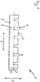
- FIG. 1 is an exemplary schematic side view of a flooring element 1 according to the invention for forming a floor covering grid 10 with a first side 2 forming a first portion 2 'and a second side 3 forming the second portion 3', wherein the flooring element 1 to the first and second sides of the second , 3 parallel main extension direction 6 and further wherein the first portion 2 'has the course of the first side 2 interrupting recesses 4 and the second portion 3' in a direction perpendicular to the main direction 6 direction 7, the recesses 4 overlapping fourth portions 5 has.
- the respective length 8 of the recesses 4 parallel to the main extension direction 6 is substantially equal to the width 9 of the floor covering element 1, wherein the distances between the recesses 4 along the main extension direction 6 are identical.
- the distance between a recess 4 in the end region of the floor covering element 1 and the end of the floor covering element 1 parallel to the main extension plane 6 is in particular approximately half as large as the constant distance between the recesses 4 with each other.
- the material of the floor covering element 1 is preferably a polyurethane (PU) -bonded rubber granulate and particularly preferably ethylene, propylene, diene monomer (EPDM) gum granulate, or a recycled rubber granulate bonded with a binder, preferably PU.
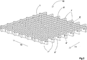
- FIG. 2 an exemplary schematic perspective view of a floor covering grid according to the invention 10 is shown with a plurality of flooring elements 1 according to the invention, wherein a plurality of first floor covering elements 1 'in a first direction 11 are arranged side by side and parallel to each other and a plurality of second Floor covering elements 1 "in a direction perpendicular to the first direction 11 second direction 12 are arranged side by side and parallel to each other, that the third portions 5 of the first floor covering elements 1 'in the recesses 4 of the second floor covering elements 1" engage.
- the intervention comprises a frictional, positive and / or material connection.
- floor covering elements 1 project beyond the regular grid arrangement in such a way that free recesses 4 of the first and second floor covering elements 1 ', 1 "protrude from the regular floor covering grid 10, with one edge side 20 projecting beyond a free recess 4
- Floor covering element 1 and the vertical edge side 20 'has a projecting with a free recess 4 first floor covering element 1'.
- first and second floor covering elements 1 ', 1 are arranged offset from one another parallel to the second and first directions 12, 11, with only second floor covering elements 1" with free recesses 4 projecting on one edge side 20, while on an opposite edge side 20
- the interlocking of the floor covering grid 10 with another, not illustrated, floor covering grid of the same orientation into the free recesses 5 "on the edge side 20 is possible.
- FIG. 3 a schematic perspective view of an inventive arrangement of flooring gratings 10 is shown, wherein two Bodenbelungsgitter 10 ', 10 "of two sizes have a common edge region 20"', wherein in the edge region 20 '"protruding fourth portions 5 of a floor covering element 1 of the first floor covering grid 10' in the protruding free recesses 4 of a floor covering element 1 of the second floor covering lattice 10 "engage, so that a mechanically stable connection between the first and the second floor covering lattice 10 ', 10" is realized.
- FIG. 4 is a schematic perspective view of an inventive Floor covering grid element 100 shown, wherein the Bodenbelungsgitterelement 100 a main extension plane 101, a plurality of first struts 102 and a plurality of perpendicular to the first struts 102 arranged second struts 103, wherein in the region of a first edge side 105 of the Bodenbelagsgitterelements 100, the first struts 102 first Ein fatigueaussparts 105 and wherein in the region of one of the first edge side 104 in the main extension plane 101 opposite second edge side 105 of the Bodenbelagsgitterelements 100, the second struts 103 have second Einitatiaussparieux and further wherein the first and the second strut 102, 103 are integrally formed and in particular produced in one piece.
- the first struts 102 have third attachment recesses 109, wherein in the region of one of the third edge side 108 in the main extension plane 101 opposite fourth edge side 110 of the Bodenbelagsgitterelements 100, the second struts 103 have a fourth Ein stressedaussparung and wherein the first and the third attachment recesses 105, 109 are opened in the direction of a first direction 120 parallel to a surface normal of the main extension plane 101, the second and the fourth attachment recesses being opened in the direction of a second direction 121 running antiparallel to the first direction 120.
Landscapes
- Engineering & Computer Science (AREA)
- Architecture (AREA)
- Civil Engineering (AREA)
- Structural Engineering (AREA)
- Floor Finish (AREA)
Claims (14)
- Treillage (10) de revêtement de sol, avec une pluralité d'éléments (1) de revêtement de sol, notamment en une matière pour passage intensif, élastique, de préférence résistant aux intempéries, l'élément (1) de revêtement de sol comportant une première zone partielle (2') formant une première face (2), une deuxième zone partielle (3') formant une deuxième face (3) et une direction d'extension principale (6) parallèle à la première et à la deuxième faces (2, 3), la première zone partielle (2') comportant au moins un évidement (4) interrompant le trajet de la première face (2) et la deuxième zone partielle (3') comportant une troisième zone partielle (5) chevauchant l'évidement (4) dans une direction (7) perpendiculaire à la direction d'extension principale (6), une pluralité de premiers éléments (1') de revêtement de sol étant placés dans une première direction (11), côte à côte et à la parallèle les uns des autres et une pluralité de deuxièmes éléments (1'') de revêtement de sol étant placés côte à côte et à la parallèle les uns des autres dans une deuxième direction (12) perpendiculaire à la première direction (11) de telle sorte que les troisièmes zones partielles (5) des premiers éléments (1') de revêtement de sol s'engagent dans les évidements (4) des deuxièmes éléments (1'') de revêtement de sol,
caractérisé en ce que
dans des zones marginales du treillage (10) de revêtement de sol, au moins un évidement (4) libre des premiers et/ou des deuxièmes éléments (1) de revêtement de sol débordent hors du treillage (10) de revêtement de sol. - Treillage (10) de revêtement de sol selon la revendication 1,
caractérisé en ce que
la longueur (8) de l'évidement (4) à la parallèle de la direction d'extension principale (6) est prévue en étant sensiblement égale à la largeur (9) de la troisième zone partielle (5), à la perpendiculaire de la direction d'extension principale (6) et de la direction verticale (7), de préférence l'ensemble de l'élément (1) de revêtement de sol présentant la largeur constante (9) de la troisième zone partielle (5). - Treillage (10) de revêtement de sol selon l'une quelconque des revendications précédentes,
caractérisé en ce
qu'à la parallèle de la direction d'extension principale (6), l'élément (1) de revêtement de sol présente une longueur totale de 0,1 à 20 mètres, de préférence de 0,2 à 10 mètres et de manière particulièrement préférée, de 0,25 à 3 mètres. - Treillage (10) de revêtement de sol selon l'une quelconque des revendications précédentes,
caractérisé en ce
qu'un côté marginal (20) comporte un deuxième élément (1'') de revêtement de sol débordant par un évidement (4) libre et le côté marginal (20') perpendiculaire à celui-ci comporte un premier élément (1') de revêtement de sol débordant par un évidement (4) libre. - Treillage (10) de revêtement de sol selon l'une quelconque des revendications précédentes,
caractérisé en ce que
les premiers et/ou les deuxièmes éléments (1, 1'') de revêtement de sol sont placés en étant mutuellement décalés à la parallèle de la deuxième et/ou de la première direction (12, 11), de préférence sur l'un (20) des côtés marginaux, seuls des deuxièmes éléments (1'') de revêtement de sol débordant par des évidements (4) libres, alors que sur un côté marginal (20'') opposé, des premiers éléments (1') de revêtement de sol débordent par des évidements (4) libres. - Agencement de treillages (10) de revêtement de sol selon l'une quelconque des revendications 1 à 5,
caractérisé en ce
qu'au moins deux treillages (10', 10'') comportent une zone marginale (20) commune, des évidements (4'') libres débordants dans la zone marginale (20) et des troisièmes zones partielles (5'') non engagées correspondantes d'un élément (1) de revêtement de sol du premier treillage (10') de revêtement de sol s'engageant dans les évidements (4'') libres débordants d'un élément (1) de revêtement de sol du deuxième treillage (10'') de revêtement de sol. - Treillage (10) de revêtement de sol selon l'une quelconque des revendications 1 à 5 ou agencement de treillages (10) de revêtement de sol selon la revendication 6,
caractérisé en ce
qu'un treillage (10) de revêtement de sol ou un agencement d'une pluralité de treillages (10) de revêtement de sol comporte une bordure, la bordure étant conçue de préférence de telle sorte qu'un retrait de treillages (10) individuels de revêtement de sol et/ou d'éléments (1) individuels de revêtement de sol soit empêché. - Élément (100) de treillage de revêtement de sol, avec un plan d'extension principale (101), une pluralité de premiers montants (102) et une pluralité de deuxièmes montants (103) placés à la perpendiculaire des premiers montants (102),
caractérisé en ce que
dans la région d'un premier côté marginal (104) de l'élément (100) de treillage de revêtement de sol, les premiers montants (102) comportent des premiers évidements d'accrochage (105) et dans la région d'un deuxième côté marginal (106) de l'élément (100) de treillage de revêtement de sol, opposé au premier côté marginal (104) dans le plan d'extension principale (101), les deuxièmes montants (103) comportent des deuxièmes évidements d'accrochage, l'élément (100) de treillis de revêtement de sol étant fabriqué en monobloc avec la pluralité de premiers montants (102) et la pluralité de deuxièmes montants (103). - Élément (100) de treillage de revêtement de sol selon la revendication 8,
caractérisé en ce que
dans la région d'un troisième côté marginal (108) de l'élément (100) de treillage de revêtement de sol, les premiers montants (102) comportent des troisièmes évidements d'accrochage (109, dans la région d'un quatrième côté marginal (110) de l'élément (100) de treillage de revêtement de sol, opposé au troisième côté marginal (108) dans le plan d'extension principale (101), les deuxièmes montants (103) comportant un quatrième évidement d'accrochage. - Élément (100) de treillage de revêtement de sol selon l'une quelconque des revendications 8 ou 9,
caractérisé en ce que
dans le sens d'une première direction (120) à la parallèle d'une normale à la surface du plan d'extension principale (101), les premiers et/ou les troisièmes évidements d'accrochage (105, 109) sont ouverts, les deuxièmes et/ou les quatrièmes évidements d'accrochage étant ouverts dans le sens d'une deuxième direction (121) s'étendant à l'antiparallèle de la première direction (120). - Agencement d'éléments (100) de treillage de revêtement de sol selon l'une quelconque des revendications 8 à 10,
caractérisé en ce que
par les premiers et/ou les troisièmes évidements d'accrochage, au moins un premier élément de treillage de revêtement de sol s'engage dans les deuxièmes et/ou les quatrièmes évidements d'accrochage d'un deuxième élément de treillage de revêtement de sol. - Procédé destiné à créer un treillage (10) de revêtement de sol selon l'une quelconque des revendications 1 à 5, dans une première étape de procédé, les éléments (1) de revêtement de sol étant fabriqués,
caractérisé en ce que
dans une deuxième étape de procédé, on place côte à côte, à la parallèle les uns des autres et de manière déportée les uns par rapport aux autres les premiers éléments (1') de revêtement de sol et dans une troisième étape de procédé, on place côte à côte, à la parallèle les uns des autres et de manière déportée les uns par rapport aux autres les deuxièmes éléments (1'') de revêtement de sol sur les premiers éléments (1') de revêtement de sol, de telle sorte que les troisièmes zones partielles (5) et/ou les évidements (4) des deuxièmes éléments (1'') de revêtement de sol s'engagent dans les évidements (4) et/ou dans les troisièmes zones partielles (5) des premiers éléments (1') de revêtement de sol. - Procédé selon la revendication 12, dans une troisième étape de procédé, deux treillages (10) de revêtement de sol étant joints l'un dans l'autre dans une zone marginale (20) commune, par insertion des troisièmes zones partielles (5'') débordantes de l'un (10) des treillages de revêtement de sol dans les évidements (4'') débordants de l'autre treillage (10) de revêtement de sol.
- Utilisation du treillage (10) de revêtement de sol, d'un élément (100) de treillage de revêtement de sol, d'un agencement de treillages (10) de revêtement de sol et/ou d'un agencement d'éléments de treillage de revêtement de sol selon l'une quelconque des revendications 1 à 11 en tant que support au sol, de préférence en tant que revêtement antichocs et de manière particulièrement préférée en tant que revêtement antichoc pour une aire de jeux pour enfants.
Priority Applications (1)
| Application Number | Priority Date | Filing Date | Title |
|---|---|---|---|
| PL08009090T PL2019169T5 (pl) | 2007-07-26 | 2008-05-16 | Element pokrycia podłoża, krata pokrycia podłoża i rozmieszczenie krat pokrycia podłoża, a także sposób wytwarzania krat pokrycia podłoża." |
Applications Claiming Priority (1)
| Application Number | Priority Date | Filing Date | Title |
|---|---|---|---|
| DE102007035390A DE102007035390A1 (de) | 2007-07-26 | 2007-07-26 | Bodenbelagselement, Bodenbelagsgitter und Anordnung von Bodenbelagsgittern, sowie Herstellungsverfahren eines Bodenbelagsgitters |
Publications (4)
| Publication Number | Publication Date |
|---|---|
| EP2019169A2 EP2019169A2 (fr) | 2009-01-28 |
| EP2019169A3 EP2019169A3 (fr) | 2014-05-07 |
| EP2019169B1 true EP2019169B1 (fr) | 2017-02-15 |
| EP2019169B2 EP2019169B2 (fr) | 2021-09-22 |
Family
ID=39864902
Family Applications (1)
| Application Number | Title | Priority Date | Filing Date |
|---|---|---|---|
| EP08009090.5A Active EP2019169B2 (fr) | 2007-07-26 | 2008-05-16 | Elément de revêtement de sol, grille de revêtement de sol et agencement de grilles de revêtement de sol ainsi que procédé de fabrication d'une grille de revêtement de sol |
Country Status (5)
| Country | Link |
|---|---|
| EP (1) | EP2019169B2 (fr) |
| DE (2) | DE102007035390A1 (fr) |
| DK (1) | DK2019169T4 (fr) |
| ES (1) | ES2624594T5 (fr) |
| PL (1) | PL2019169T5 (fr) |
Cited By (2)
| Publication number | Priority date | Publication date | Assignee | Title |
|---|---|---|---|---|
| WO2020002956A1 (fr) | 2018-06-26 | 2020-01-02 | Szonyi Nandor | Élément de revêtement de sol de protection contre les chutes destiné principalement à recouvrir des terrains de jeu et revêtement de sol composé de celui-ci |
| DE102023125822A1 (de) | 2023-09-22 | 2025-03-27 | Conradi + Kaiser Gmbh | Schalldämmsystem für einen Fußboden |
Families Citing this family (4)
| Publication number | Priority date | Publication date | Assignee | Title |
|---|---|---|---|---|
| DE102015013666A1 (de) | 2015-10-23 | 2017-04-27 | Conradi + Kaiser Gmbh | Bodenbelags-System und Bodenbelag für Spielplätze, Sportflächen und dergleichen, sowie Verfahren zur Bildung eines Bodenbelags |
| DE102016204798A1 (de) * | 2016-03-23 | 2017-09-28 | Wolfgang Bacher | Reitboden, Gitterstruktur zum Einbau in einen Reitboden und Verfahren zum Bau eines Reitbodens |
| CN109795438B (zh) * | 2019-03-18 | 2024-07-19 | 赵小清 | 一种碰撞防护装置 |
| DE102020111582A1 (de) | 2020-04-28 | 2021-10-28 | Conradi + Kaiser Gmbh | Flammenhemmendes elastisches Bodenbelagselement |
Citations (17)
| Publication number | Priority date | Publication date | Assignee | Title |
|---|---|---|---|---|
| US1158154A (en) * | 1914-02-13 | 1915-10-26 | Chester B Albree | Grating. |
| US2335181A (en) * | 1942-04-30 | 1943-11-23 | Smith Corp A O | Method of manufacturing grating |
| US4111585A (en) | 1977-04-27 | 1978-09-05 | Mascaro Thomas C | Module and modular support for turfgrass and like areas |
| DE3140701A1 (de) | 1981-10-14 | 1983-04-28 | Hermann 5300 Bonn Barstadt | Gitterkoerper, insbesondere rasendraenkoerper, fuer mechanisch hoch beanspruchte rasenflaechen |
| US4436779A (en) | 1982-07-02 | 1984-03-13 | Menconi K Anthony | Modular surface such as for use in sports |
| DE8527295U1 (de) * | 1985-09-25 | 1985-10-31 | Menzel, Hans C., Dr., 7000 Stuttgart | Vegetationsgitterstein |
| US4584221A (en) | 1984-07-19 | 1986-04-22 | Sportforderung Peter Kung Ag | Floor covering assembly |
| DE3737017A1 (de) | 1987-10-31 | 1989-05-11 | Heinz Hoesmann | Bauelement |
| US4928471A (en) * | 1988-06-08 | 1990-05-29 | Ohio Gratings, Inc. | Grating construction |
| US4930286A (en) | 1988-03-14 | 1990-06-05 | Daniel Kotler | Modular sports tile with lateral absorption |
| DE4114572A1 (de) | 1991-05-04 | 1992-11-05 | Walter Zink | Dachdeckung fuer geneigte dachflaechen |
| US5509244A (en) | 1991-05-13 | 1996-04-23 | Bentzon; Frank | Flooring system having joinable tile elements, particularly plastic tiles |
| US5604949A (en) * | 1995-10-10 | 1997-02-25 | Mangone Enterprises | Weld-free gratings for bridge decks |
| US5761867A (en) | 1996-10-11 | 1998-06-09 | Sport Court, Inc. | Tile support insert |
| DE20121313U1 (de) * | 2001-01-11 | 2002-08-01 | Veeh, Helmut, 97215 Uffenheim | Bodenbelagplatte |
| US20060070314A1 (en) | 2004-10-06 | 2006-04-06 | Connor Sport Court Int'l., Inc. | Tile with multiple-level surface |
| DE102005002854A1 (de) * | 2005-01-20 | 2006-08-24 | Conradi + Kaiser Gmbh | Fallschutzplatte, insbesondere für den Außenbereich, Fallschutzbelag, Verwendung einer Fallschutzplatte |
Family Cites Families (8)
| Publication number | Priority date | Publication date | Assignee | Title |
|---|---|---|---|---|
| AT388950B (de) * | 1985-11-22 | 1989-09-25 | Spiess Kunststoff Recycling | Gitterplatte aus kunststoff, insbesondere aus recycling-kunststoff |
| US5787654A (en) * | 1995-09-21 | 1998-08-04 | Sport Court, Inc. | Isogrid tile |
| GB2359311B (en) * | 2000-02-02 | 2003-11-12 | Sutcliffe Play Ltd | Safety tiles for paving a playground area |
| AUPR455601A0 (en) * | 2001-04-24 | 2001-05-24 | Strathayr Pty. Limited | Liftable turfing systems |
| DE102004032783A1 (de) * | 2004-07-06 | 2006-02-16 | Conradi + Kaiser Gmbh | Platte zur Bildung eines Belags, insbesondere für den Aussenbereich, und Belag |
| DE102004060822A1 (de) * | 2004-12-17 | 2006-07-06 | Recover Systems Gmbh | Rasengitterstein |
| DE202005015107U1 (de) * | 2005-09-24 | 2005-12-29 | HÜBNER-LEE Ernst Hübner e.K. | Gitterplatte |
| DE202005018780U1 (de) * | 2005-12-01 | 2006-02-02 | Sagustu Spezialbelag-Vertriebs-Gmbh | Bodenmatte für Tiere, insbesondere Pferde |
-
2007
- 2007-07-26 DE DE102007035390A patent/DE102007035390A1/de not_active Ceased
-
2008
- 2008-05-16 DE DE202008018440.1U patent/DE202008018440U1/de not_active Expired - Lifetime
- 2008-05-16 ES ES08009090T patent/ES2624594T5/es active Active
- 2008-05-16 EP EP08009090.5A patent/EP2019169B2/fr active Active
- 2008-05-16 DK DK08009090.5T patent/DK2019169T4/da active
- 2008-05-16 PL PL08009090T patent/PL2019169T5/pl unknown
Patent Citations (17)
| Publication number | Priority date | Publication date | Assignee | Title |
|---|---|---|---|---|
| US1158154A (en) * | 1914-02-13 | 1915-10-26 | Chester B Albree | Grating. |
| US2335181A (en) * | 1942-04-30 | 1943-11-23 | Smith Corp A O | Method of manufacturing grating |
| US4111585A (en) | 1977-04-27 | 1978-09-05 | Mascaro Thomas C | Module and modular support for turfgrass and like areas |
| DE3140701A1 (de) | 1981-10-14 | 1983-04-28 | Hermann 5300 Bonn Barstadt | Gitterkoerper, insbesondere rasendraenkoerper, fuer mechanisch hoch beanspruchte rasenflaechen |
| US4436779A (en) | 1982-07-02 | 1984-03-13 | Menconi K Anthony | Modular surface such as for use in sports |
| US4584221A (en) | 1984-07-19 | 1986-04-22 | Sportforderung Peter Kung Ag | Floor covering assembly |
| DE8527295U1 (de) * | 1985-09-25 | 1985-10-31 | Menzel, Hans C., Dr., 7000 Stuttgart | Vegetationsgitterstein |
| DE3737017A1 (de) | 1987-10-31 | 1989-05-11 | Heinz Hoesmann | Bauelement |
| US4930286A (en) | 1988-03-14 | 1990-06-05 | Daniel Kotler | Modular sports tile with lateral absorption |
| US4928471A (en) * | 1988-06-08 | 1990-05-29 | Ohio Gratings, Inc. | Grating construction |
| DE4114572A1 (de) | 1991-05-04 | 1992-11-05 | Walter Zink | Dachdeckung fuer geneigte dachflaechen |
| US5509244A (en) | 1991-05-13 | 1996-04-23 | Bentzon; Frank | Flooring system having joinable tile elements, particularly plastic tiles |
| US5604949A (en) * | 1995-10-10 | 1997-02-25 | Mangone Enterprises | Weld-free gratings for bridge decks |
| US5761867A (en) | 1996-10-11 | 1998-06-09 | Sport Court, Inc. | Tile support insert |
| DE20121313U1 (de) * | 2001-01-11 | 2002-08-01 | Veeh, Helmut, 97215 Uffenheim | Bodenbelagplatte |
| US20060070314A1 (en) | 2004-10-06 | 2006-04-06 | Connor Sport Court Int'l., Inc. | Tile with multiple-level surface |
| DE102005002854A1 (de) * | 2005-01-20 | 2006-08-24 | Conradi + Kaiser Gmbh | Fallschutzplatte, insbesondere für den Außenbereich, Fallschutzbelag, Verwendung einer Fallschutzplatte |
Cited By (5)
| Publication number | Priority date | Publication date | Assignee | Title |
|---|---|---|---|---|
| WO2020002956A1 (fr) | 2018-06-26 | 2020-01-02 | Szonyi Nandor | Élément de revêtement de sol de protection contre les chutes destiné principalement à recouvrir des terrains de jeu et revêtement de sol composé de celui-ci |
| US10968573B2 (en) | 2018-06-26 | 2021-04-06 | Nándor Szönyi | Fall protecting flooring element primarily for covering playgrounds and flooring composed therefrom |
| AU2018429406B2 (en) * | 2018-06-26 | 2025-01-23 | Nándor SZŐNYI | Fall protecting flooring element primarily for covering playgrounds and flooring composed therefrom |
| DE102023125822A1 (de) | 2023-09-22 | 2025-03-27 | Conradi + Kaiser Gmbh | Schalldämmsystem für einen Fußboden |
| WO2025062035A1 (fr) | 2023-09-22 | 2025-03-27 | Conradi + Kaiser Gmbh | Système d'isolation phonique pour sol |
Also Published As
| Publication number | Publication date |
|---|---|
| DK2019169T4 (da) | 2021-12-20 |
| ES2624594T3 (es) | 2017-07-17 |
| PL2019169T5 (pl) | 2022-01-17 |
| DE202008018440U1 (de) | 2014-01-10 |
| DK2019169T3 (en) | 2017-05-22 |
| PL2019169T3 (pl) | 2017-08-31 |
| EP2019169B2 (fr) | 2021-09-22 |
| ES2624594T5 (es) | 2022-01-26 |
| EP2019169A2 (fr) | 2009-01-28 |
| DE102007035390A1 (de) | 2009-01-29 |
| EP2019169A3 (fr) | 2014-05-07 |
Similar Documents
| Publication | Publication Date | Title |
|---|---|---|
| EP2019169B2 (fr) | Elément de revêtement de sol, grille de revêtement de sol et agencement de grilles de revêtement de sol ainsi que procédé de fabrication d'une grille de revêtement de sol | |
| EP0816564A2 (fr) | Renforcement pour aires de circulation avec des pavés ou des dalles | |
| DE202014106285U1 (de) | Kunststoff-Mehrzweckbauteil | |
| DE2945292A1 (de) | Kunststoffbegrenzungselement | |
| DE9103772U1 (de) | Rasenbefestigungsplatte | |
| EP0058825B1 (fr) | Dalle de revêtement de sécurité élastiquement résiliente | |
| DE102020008105B4 (de) | Begrünbares Wandelement | |
| DE202005015107U1 (de) | Gitterplatte | |
| DE102017114192A1 (de) | Solarpoolabdeckung | |
| DE1559553A1 (de) | Gitterosteinheit,bestehend aus einem Rost und einem Rahmen | |
| DE3816127C2 (de) | Bepflanzbare Lärmschutzwand | |
| EP3365496B1 (fr) | Système de revêtement de sol et revêtement de sol pour aires de jeu et aires de pratiques sportives, et procédé pour le produire | |
| DE202007017767U1 (de) | Reitplatz-Bodenbefestigungsvorrichtung | |
| EP0286957B1 (fr) | Mur anti-bruit support de végétation | |
| DE19640819A1 (de) | Verlegeelementanordnung für befestigte Rasenflächen | |
| DE19704425C2 (de) | Kunststeinelement | |
| EP3101367A1 (fr) | Système solaire | |
| DE102004032783A1 (de) | Platte zur Bildung eines Belags, insbesondere für den Aussenbereich, und Belag | |
| DE8322275U1 (de) | Rasenabdeckplatte für Straßenbankette | |
| EP0212036A1 (fr) | Pierre interconnectable pour gazon | |
| DE2532572C2 (de) | Elastisches, flächiges Zaunelement Döring, Erich, 8052 Moosburg | |
| DE1960918C3 (de) | Aufrollbarer Stabrost zur Abdeckung räumlich begrenzter Vertiefungen | |
| DE2616829A1 (de) | Federnd nachgiebiger, unterlagenaehnlicher aufbau oder struktur | |
| DE102016011535A1 (de) | Bauelement zur Verwendung im Pflasterbau sowie Pflasteranordnung | |
| EP1308561B1 (fr) | Caillebotis et mécanisme de fixation |
Legal Events
| Date | Code | Title | Description |
|---|---|---|---|
| PUAI | Public reference made under article 153(3) epc to a published international application that has entered the european phase |
Free format text: ORIGINAL CODE: 0009012 |
|
| AK | Designated contracting states |
Kind code of ref document: A2 Designated state(s): AT BE BG CH CY CZ DE DK EE ES FI FR GB GR HR HU IE IS IT LI LT LU LV MC MT NL NO PL PT RO SE SI SK TR |
|
| AX | Request for extension of the european patent |
Extension state: AL BA MK RS |
|
| 17P | Request for examination filed |
Effective date: 20090703 |
|
| PUAL | Search report despatched |
Free format text: ORIGINAL CODE: 0009013 |
|
| AK | Designated contracting states |
Kind code of ref document: A3 Designated state(s): AT BE BG CH CY CZ DE DK EE ES FI FR GB GR HR HU IE IS IT LI LT LU LV MC MT NL NO PL PT RO SE SI SK TR |
|
| AX | Request for extension of the european patent |
Extension state: AL BA MK RS |
|
| RIC1 | Information provided on ipc code assigned before grant |
Ipc: E01C 13/04 20060101ALI20140331BHEP Ipc: E01C 9/00 20060101AFI20140331BHEP |
|
| AKX | Designation fees paid |
Designated state(s): AT BE BG CH CY CZ DE DK EE ES FI FR GB GR HR HU IE IS IT LI LT LU LV MC MT NL NO PL PT RO SE SI SK TR |
|
| AXX | Extension fees paid |
Extension state: RS Extension state: BA Extension state: AL Extension state: MK |
|
| TPAC | Observations filed by third parties |
Free format text: ORIGINAL CODE: EPIDOSNTIPA |
|
| 17Q | First examination report despatched |
Effective date: 20150603 |
|
| GRAP | Despatch of communication of intention to grant a patent |
Free format text: ORIGINAL CODE: EPIDOSNIGR1 |
|
| INTG | Intention to grant announced |
Effective date: 20161026 |
|
| GRAS | Grant fee paid |
Free format text: ORIGINAL CODE: EPIDOSNIGR3 |
|
| STAA | Information on the status of an ep patent application or granted ep patent |
Free format text: STATUS: GRANT OF PATENT IS INTENDED |
|
| GRAA | (expected) grant |
Free format text: ORIGINAL CODE: 0009210 |
|
| STAA | Information on the status of an ep patent application or granted ep patent |
Free format text: STATUS: THE PATENT HAS BEEN GRANTED |
|
| AK | Designated contracting states |
Kind code of ref document: B1 Designated state(s): AT BE BG CH CY CZ DE DK EE ES FI FR GB GR HR HU IE IS IT LI LT LU LV MC MT NL NO PL PT RO SE SI SK TR |
|
| REG | Reference to a national code |
Ref country code: GB Ref legal event code: FG4D Free format text: NOT ENGLISH Ref country code: CH Ref legal event code: EP |
|
| REG | Reference to a national code |
Ref country code: IE Ref legal event code: FG4D Free format text: LANGUAGE OF EP DOCUMENT: GERMAN |
|
| REG | Reference to a national code |
Ref country code: AT Ref legal event code: REF Ref document number: 867970 Country of ref document: AT Kind code of ref document: T Effective date: 20170315 |
|
| REG | Reference to a national code |
Ref country code: DE Ref legal event code: R096 Ref document number: 502008015024 Country of ref document: DE |
|
| REG | Reference to a national code |
Ref country code: DK Ref legal event code: T3 Effective date: 20170516 |
|
| REG | Reference to a national code |
Ref country code: NL Ref legal event code: FP |
|
| REG | Reference to a national code |
Ref country code: SE Ref legal event code: TRGR Ref country code: FR Ref legal event code: PLFP Year of fee payment: 10 |
|
| REG | Reference to a national code |
Ref country code: NO Ref legal event code: T2 Effective date: 20170215 |
|
| REG | Reference to a national code |
Ref country code: LT Ref legal event code: MG4D |
|
| REG | Reference to a national code |
Ref country code: ES Ref legal event code: FG2A Ref document number: 2624594 Country of ref document: ES Kind code of ref document: T3 Effective date: 20170717 |
|
| PG25 | Lapsed in a contracting state [announced via postgrant information from national office to epo] |
Ref country code: HR Free format text: LAPSE BECAUSE OF FAILURE TO SUBMIT A TRANSLATION OF THE DESCRIPTION OR TO PAY THE FEE WITHIN THE PRESCRIBED TIME-LIMIT Effective date: 20170215 Ref country code: GR Free format text: LAPSE BECAUSE OF FAILURE TO SUBMIT A TRANSLATION OF THE DESCRIPTION OR TO PAY THE FEE WITHIN THE PRESCRIBED TIME-LIMIT Effective date: 20170516 Ref country code: LT Free format text: LAPSE BECAUSE OF FAILURE TO SUBMIT A TRANSLATION OF THE DESCRIPTION OR TO PAY THE FEE WITHIN THE PRESCRIBED TIME-LIMIT Effective date: 20170215 |
|
| PG25 | Lapsed in a contracting state [announced via postgrant information from national office to epo] |
Ref country code: BG Free format text: LAPSE BECAUSE OF FAILURE TO SUBMIT A TRANSLATION OF THE DESCRIPTION OR TO PAY THE FEE WITHIN THE PRESCRIBED TIME-LIMIT Effective date: 20170515 Ref country code: PT Free format text: LAPSE BECAUSE OF FAILURE TO SUBMIT A TRANSLATION OF THE DESCRIPTION OR TO PAY THE FEE WITHIN THE PRESCRIBED TIME-LIMIT Effective date: 20170615 Ref country code: LV Free format text: LAPSE BECAUSE OF FAILURE TO SUBMIT A TRANSLATION OF THE DESCRIPTION OR TO PAY THE FEE WITHIN THE PRESCRIBED TIME-LIMIT Effective date: 20170215 |
|
| PG25 | Lapsed in a contracting state [announced via postgrant information from national office to epo] |
Ref country code: SK Free format text: LAPSE BECAUSE OF FAILURE TO SUBMIT A TRANSLATION OF THE DESCRIPTION OR TO PAY THE FEE WITHIN THE PRESCRIBED TIME-LIMIT Effective date: 20170215 Ref country code: EE Free format text: LAPSE BECAUSE OF FAILURE TO SUBMIT A TRANSLATION OF THE DESCRIPTION OR TO PAY THE FEE WITHIN THE PRESCRIBED TIME-LIMIT Effective date: 20170215 Ref country code: RO Free format text: LAPSE BECAUSE OF FAILURE TO SUBMIT A TRANSLATION OF THE DESCRIPTION OR TO PAY THE FEE WITHIN THE PRESCRIBED TIME-LIMIT Effective date: 20170215 Ref country code: CZ Free format text: LAPSE BECAUSE OF FAILURE TO SUBMIT A TRANSLATION OF THE DESCRIPTION OR TO PAY THE FEE WITHIN THE PRESCRIBED TIME-LIMIT Effective date: 20170215 |
|
| REG | Reference to a national code |
Ref country code: DE Ref legal event code: R026 Ref document number: 502008015024 Country of ref document: DE |
|
| PLBI | Opposition filed |
Free format text: ORIGINAL CODE: 0009260 |
|
| PLAX | Notice of opposition and request to file observation + time limit sent |
Free format text: ORIGINAL CODE: EPIDOSNOBS2 |
|
| 26 | Opposition filed |
Opponent name: GUM-TECH S.R.O. Effective date: 20171113 |
|
| PG25 | Lapsed in a contracting state [announced via postgrant information from national office to epo] |
Ref country code: MC Free format text: LAPSE BECAUSE OF FAILURE TO SUBMIT A TRANSLATION OF THE DESCRIPTION OR TO PAY THE FEE WITHIN THE PRESCRIBED TIME-LIMIT Effective date: 20170215 |
|
| REG | Reference to a national code |
Ref country code: IE Ref legal event code: MM4A |
|
| PG25 | Lapsed in a contracting state [announced via postgrant information from national office to epo] |
Ref country code: SI Free format text: LAPSE BECAUSE OF FAILURE TO SUBMIT A TRANSLATION OF THE DESCRIPTION OR TO PAY THE FEE WITHIN THE PRESCRIBED TIME-LIMIT Effective date: 20170215 |
|
| PG25 | Lapsed in a contracting state [announced via postgrant information from national office to epo] |
Ref country code: IE Free format text: LAPSE BECAUSE OF NON-PAYMENT OF DUE FEES Effective date: 20170516 |
|
| REG | Reference to a national code |
Ref country code: FR Ref legal event code: PLFP Year of fee payment: 11 |
|
| PLBB | Reply of patent proprietor to notice(s) of opposition received |
Free format text: ORIGINAL CODE: EPIDOSNOBS3 |
|
| PG25 | Lapsed in a contracting state [announced via postgrant information from national office to epo] |
Ref country code: MT Free format text: LAPSE BECAUSE OF FAILURE TO SUBMIT A TRANSLATION OF THE DESCRIPTION OR TO PAY THE FEE WITHIN THE PRESCRIBED TIME-LIMIT Effective date: 20170215 |
|
| PG25 | Lapsed in a contracting state [announced via postgrant information from national office to epo] |
Ref country code: HU Free format text: LAPSE BECAUSE OF FAILURE TO SUBMIT A TRANSLATION OF THE DESCRIPTION OR TO PAY THE FEE WITHIN THE PRESCRIBED TIME-LIMIT; INVALID AB INITIO Effective date: 20080516 |
|
| APBM | Appeal reference recorded |
Free format text: ORIGINAL CODE: EPIDOSNREFNO |
|
| APBP | Date of receipt of notice of appeal recorded |
Free format text: ORIGINAL CODE: EPIDOSNNOA2O |
|
| APAH | Appeal reference modified |
Free format text: ORIGINAL CODE: EPIDOSCREFNO |
|
| APBM | Appeal reference recorded |
Free format text: ORIGINAL CODE: EPIDOSNREFNO |
|
| APBP | Date of receipt of notice of appeal recorded |
Free format text: ORIGINAL CODE: EPIDOSNNOA2O |
|
| APAW | Appeal reference deleted |
Free format text: ORIGINAL CODE: EPIDOSDREFNO |
|
| APBQ | Date of receipt of statement of grounds of appeal recorded |
Free format text: ORIGINAL CODE: EPIDOSNNOA3O |
|
| PG25 | Lapsed in a contracting state [announced via postgrant information from national office to epo] |
Ref country code: CY Free format text: LAPSE BECAUSE OF NON-PAYMENT OF DUE FEES Effective date: 20170215 |
|
| PG25 | Lapsed in a contracting state [announced via postgrant information from national office to epo] |
Ref country code: TR Free format text: LAPSE BECAUSE OF FAILURE TO SUBMIT A TRANSLATION OF THE DESCRIPTION OR TO PAY THE FEE WITHIN THE PRESCRIBED TIME-LIMIT Effective date: 20170215 |
|
| PG25 | Lapsed in a contracting state [announced via postgrant information from national office to epo] |
Ref country code: IS Free format text: LAPSE BECAUSE OF FAILURE TO SUBMIT A TRANSLATION OF THE DESCRIPTION OR TO PAY THE FEE WITHIN THE PRESCRIBED TIME-LIMIT Effective date: 20170615 |
|
| APBU | Appeal procedure closed |
Free format text: ORIGINAL CODE: EPIDOSNNOA9O |
|
| PUAH | Patent maintained in amended form |
Free format text: ORIGINAL CODE: 0009272 |
|
| STAA | Information on the status of an ep patent application or granted ep patent |
Free format text: STATUS: PATENT MAINTAINED AS AMENDED |
|
| 27A | Patent maintained in amended form |
Effective date: 20210922 |
|
| AK | Designated contracting states |
Kind code of ref document: B2 Designated state(s): AT BE BG CH CY CZ DE DK EE ES FI FR GB GR HR HU IE IS IT LI LT LU LV MC MT NL NO PL PT RO SE SI SK TR |
|
| REG | Reference to a national code |
Ref country code: DE Ref legal event code: R102 Ref document number: 502008015024 Country of ref document: DE |
|
| REG | Reference to a national code |
Ref country code: DK Ref legal event code: T4 Effective date: 20211217 |
|
| REG | Reference to a national code |
Ref country code: SE Ref legal event code: RPEO |
|
| REG | Reference to a national code |
Ref country code: NL Ref legal event code: FP Ref country code: ES Ref legal event code: DC2A Ref document number: 2624594 Country of ref document: ES Kind code of ref document: T5 Effective date: 20220126 |
|
| REG | Reference to a national code |
Ref country code: NO Ref legal event code: TB2 |
|
| REG | Reference to a national code |
Ref country code: DE Ref legal event code: R082 Ref document number: 502008015024 Country of ref document: DE Representative=s name: GESKES PATENT- UND RECHTSANWAELTE, DE |
|
| PGFP | Annual fee paid to national office [announced via postgrant information from national office to epo] |
Ref country code: NL Payment date: 20250522 Year of fee payment: 18 |
|
| PGFP | Annual fee paid to national office [announced via postgrant information from national office to epo] |
Ref country code: FI Payment date: 20250520 Year of fee payment: 18 |
|
| PGFP | Annual fee paid to national office [announced via postgrant information from national office to epo] |
Ref country code: DE Payment date: 20250526 Year of fee payment: 18 Ref country code: PL Payment date: 20250505 Year of fee payment: 18 |
|
| PGFP | Annual fee paid to national office [announced via postgrant information from national office to epo] |
Ref country code: GB Payment date: 20250522 Year of fee payment: 18 Ref country code: ES Payment date: 20250616 Year of fee payment: 18 Ref country code: DK Payment date: 20250521 Year of fee payment: 18 |
|
| PGFP | Annual fee paid to national office [announced via postgrant information from national office to epo] |
Ref country code: NO Payment date: 20250520 Year of fee payment: 18 |
|
| PGFP | Annual fee paid to national office [announced via postgrant information from national office to epo] |
Ref country code: IT Payment date: 20250530 Year of fee payment: 18 Ref country code: LU Payment date: 20250520 Year of fee payment: 18 Ref country code: BE Payment date: 20250520 Year of fee payment: 18 |
|
| PGFP | Annual fee paid to national office [announced via postgrant information from national office to epo] |
Ref country code: FR Payment date: 20250523 Year of fee payment: 18 |
|
| PGFP | Annual fee paid to national office [announced via postgrant information from national office to epo] |
Ref country code: CH Payment date: 20250601 Year of fee payment: 18 |
|
| PGFP | Annual fee paid to national office [announced via postgrant information from national office to epo] |
Ref country code: AT Payment date: 20250519 Year of fee payment: 18 |
|
| PGFP | Annual fee paid to national office [announced via postgrant information from national office to epo] |
Ref country code: SE Payment date: 20250522 Year of fee payment: 18 |