EP2019227A1 - Schwingungsdämpfungsträgervorrichtung - Google Patents
Schwingungsdämpfungsträgervorrichtung Download PDFInfo
- Publication number
- EP2019227A1 EP2019227A1 EP07741353A EP07741353A EP2019227A1 EP 2019227 A1 EP2019227 A1 EP 2019227A1 EP 07741353 A EP07741353 A EP 07741353A EP 07741353 A EP07741353 A EP 07741353A EP 2019227 A1 EP2019227 A1 EP 2019227A1
- Authority
- EP
- European Patent Office
- Prior art keywords
- load
- stopper
- mounting member
- load transmission
- elastic body
- Prior art date
- Legal status (The legal status is an assumption and is not a legal conclusion. Google has not performed a legal analysis and makes no representation as to the accuracy of the status listed.)
- Granted
Links
Images




Classifications
-
- F—MECHANICAL ENGINEERING; LIGHTING; HEATING; WEAPONS; BLASTING
- F16—ENGINEERING ELEMENTS AND UNITS; GENERAL MEASURES FOR PRODUCING AND MAINTAINING EFFECTIVE FUNCTIONING OF MACHINES OR INSTALLATIONS; THERMAL INSULATION IN GENERAL
- F16F—SPRINGS; SHOCK-ABSORBERS; MEANS FOR DAMPING VIBRATION
- F16F1/00—Springs
- F16F1/36—Springs made of rubber or other material having high internal friction, e.g. thermoplastic elastomers
- F16F1/38—Springs made of rubber or other material having high internal friction, e.g. thermoplastic elastomers with a sleeve of elastic material between a rigid outer sleeve and a rigid inner sleeve or pin, i.e. bushing-type
- F16F1/3828—End stop features or buffering
-
- B—PERFORMING OPERATIONS; TRANSPORTING
- B60—VEHICLES IN GENERAL
- B60K—ARRANGEMENT OR MOUNTING OF PROPULSION UNITS OR OF TRANSMISSIONS IN VEHICLES; ARRANGEMENT OR MOUNTING OF PLURAL DIVERSE PRIME-MOVERS IN VEHICLES; AUXILIARY DRIVES FOR VEHICLES; INSTRUMENTATION OR DASHBOARDS FOR VEHICLES; ARRANGEMENTS IN CONNECTION WITH COOLING, AIR INTAKE, GAS EXHAUST OR FUEL SUPPLY OF PROPULSION UNITS IN VEHICLES
- B60K5/00—Arrangement or mounting of internal-combustion or jet-propulsion units
- B60K5/12—Arrangement of engine supports
- B60K5/1208—Resilient supports
-
- F—MECHANICAL ENGINEERING; LIGHTING; HEATING; WEAPONS; BLASTING
- F16—ENGINEERING ELEMENTS AND UNITS; GENERAL MEASURES FOR PRODUCING AND MAINTAINING EFFECTIVE FUNCTIONING OF MACHINES OR INSTALLATIONS; THERMAL INSULATION IN GENERAL
- F16F—SPRINGS; SHOCK-ABSORBERS; MEANS FOR DAMPING VIBRATION
- F16F3/00—Spring units consisting of several springs, e.g. for obtaining a desired spring characteristic
- F16F3/08—Spring units consisting of several springs, e.g. for obtaining a desired spring characteristic with springs made of a material having high internal friction, e.g. rubber
- F16F3/087—Units comprising several springs made of plastics or the like material
- F16F3/0873—Units comprising several springs made of plastics or the like material of the same material or the material not being specified
Definitions
- FF type vehicle front-engine, front-drive type
- power unit supports of inertial main axis type and similar types, a peripheral portion of the power unit away from the torque axis it elastically connected to the vehicle body, limiting the displacement amount of the power unit relative to the vehicle body in the rolling direction shock absorption (see, for example, patent documents 1 and 2).
- the stopper member to which load has been applied, elastically deforms in the load input direction between the load transmission surfaces of the stopper member and the load bearing surfaces of the second mounting member. Since the load transmission surfaces and the load bearing surfaces each extend in a direction that intersects with the load orthogonal direction, and are also mutually parallel to each other, it can be set such that the elastic deformation occurring in the stopper elastic body includes a main component of a shear deformation component, and a secondary component of a compressive and tensile deformation component, being slight in comparison to the shear deformation component.
- the vibration damping support apparatus when load is input to the first mounting member or to the second mounting member along the load input direction, the main elastic body elastically deforms along the load input direction, and the first mounting member displaces relative to the second mounting member along the load input direction.
- the displacement amount of the first mounting member in the load input direction becomes that of the initial separation along the load input direction of the stopper member from the first mounting member, or a greater amount, the first mounting member contacts the stopper member, and load is transferred to the stopper elastic body through the stopper member.
- the vibration damping support apparatus according to claim 4 of the present invention is the vibration damping support apparatus of claim 1 or claim 2, wherein the angle ⁇ 2 of the load transmission surfaces relative to the load input direction is 0° ⁇ ⁇ 2 ⁇ 45°, and the angle ⁇ 3 of the load bearing surfaces relative to the load input direction is 0° ⁇ ⁇ 3 ⁇ 45°.
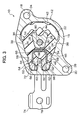
- Load bearing surfaces 34 are formed at each side along the height direction of the inner peripheral surface in the external cylinder fitting 12, the load bearing surfaces 34 formed as surfaces that are each substantially flat and parallel to respective surfaces of the pair of load transmission surfaces 28. Each of the pair of load bearing surfaces 34 is disposed so as to be displaced to the vehicle front side relative to the respective load transmission surface 28.
- a stopper elastic body 64 is disposed in the torque rod 10 between the external cylinder fitting 12 and the stopper fitting 46.
- the overall cross-sectional shape of the stopper elastic body 64 is substantially V-shaped, opening toward the vehicle front side.
- Outer body parts 66 are formed with substantially diamond shaped cross-sections to the stopper elastic body 64, between the first load transmission surfaces 54 and the first load bearing surfaces 58.
- Inner body parts 68 are also formed with substantially diamond shaped cross-sections to the stopper elastic body 64, between the second load transmission surfaces 56 and the second load bearing surfaces 62.
- the first covering portion 70 vulcanize bonded to the rear surface of the contact plate portion 50 faces the covering portion 40 vulcanize bonded to the leading end face of the internal cylinder fitting 14 with a specific gap GR therebetween when in a neutral state in which the main elastic body 36 is not elastically deformed.
- a bolt 80 is inserted through the connection holes 76 of the pair of connecting arms 74 and the connection holes 30 of the internal cylinder fitting 14, and a nut 82 is threaded onto a leading end portion of the bolt 80 protruding out from one of the connection holes 76.
- the leading ends of the pair of connecting arms 74 are each thereby connected to the internal cylinder fitting 14 through the bolt 80 and the nut 82.
- the first load transmission surfaces 54 and the second load transmission surfaces 56 are each formed as flat surfaces extending parallel to the load input direction, and the first load bearing surfaces 58 and the second load bearing surfaces 62 are also each formed as flat surfaces extending parallel to the load input direction.
- the internal cylinder fitting 14 contacts the contact plate portion 50 of the stopper fitting 46 through the covering portion 40 and the first covering portion 70, and load is transmitted through the stopper fitting 46 to the outer body parts 66 and the inner body parts 68 of the stopper elastic body 64.
- the elastic deformation occurring to the outer body parts 66 and the inner body parts 68 of the stopper elastic body 64 can thereby be configured to include a shear deformation component as the main component and a compressive and tensile deformation component as a secondary component, small in relation to the shear deformation component.
- a rapid increase in the compressive and tensile component proportion can be effectively suppressed even when the load applied in the compression direction increases.
- a sharp increase in rigidity and dynamic spring constant of the stopper elastic body 64 can be effectively prevented even when the deformation amount of the stopper elastic body 64 is large with input of a high load.
- the torque rod 90 according to the present exemplary embodiment operates in the same manner as the torque rod 10 according to the first exemplary embodiment both when a small load is input with a small displacement amount of the internal cylinder fitting 14 in the load input direction, and when an impact or high load is input in the tension direction from the power unit accompanying sudden vehicle deceleration, restricting displacement of the power unit in the roll direction and also preventing transmission of vibration and impact to the vehicle body side.
Landscapes
- Engineering & Computer Science (AREA)
- General Engineering & Computer Science (AREA)
- Mechanical Engineering (AREA)
- Chemical & Material Sciences (AREA)
- Combustion & Propulsion (AREA)
- Transportation (AREA)
- Vibration Prevention Devices (AREA)
- Arrangement Or Mounting Of Propulsion Units For Vehicles (AREA)
- Springs (AREA)
Applications Claiming Priority (2)
| Application Number | Priority Date | Filing Date | Title |
|---|---|---|---|
| JP2006109608 | 2006-04-12 | ||
| PCT/JP2007/057917 WO2007117013A1 (ja) | 2006-04-12 | 2007-04-10 | 防振支持装置 |
Publications (3)
| Publication Number | Publication Date |
|---|---|
| EP2019227A1 true EP2019227A1 (de) | 2009-01-28 |
| EP2019227A4 EP2019227A4 (de) | 2012-01-04 |
| EP2019227B1 EP2019227B1 (de) | 2013-02-27 |
Family
ID=38581284
Family Applications (1)
| Application Number | Title | Priority Date | Filing Date |
|---|---|---|---|
| EP07741353A Active EP2019227B1 (de) | 2006-04-12 | 2007-04-10 | Schwingungsdämpfungsträgervorrichtung |
Country Status (5)
| Country | Link |
|---|---|
| US (1) | US8500109B2 (de) |
| EP (1) | EP2019227B1 (de) |
| JP (1) | JP5037493B2 (de) |
| CN (1) | CN101421535B (de) |
| WO (1) | WO2007117013A1 (de) |
Cited By (1)
| Publication number | Priority date | Publication date | Assignee | Title |
|---|---|---|---|---|
| US20190070945A1 (en) * | 2017-09-01 | 2019-03-07 | Kurashiki Kako Co., Ltd. | Vibration isolation structure |
Families Citing this family (19)
| Publication number | Priority date | Publication date | Assignee | Title |
|---|---|---|---|---|
| JP4881848B2 (ja) * | 2007-12-19 | 2012-02-22 | 東海ゴム工業株式会社 | 防振連結ロッド |
| JP5363391B2 (ja) * | 2010-03-29 | 2013-12-11 | 東海ゴム工業株式会社 | トルクロッドのストッパ構造 |
| JP5548031B2 (ja) * | 2010-05-31 | 2014-07-16 | 株式会社東海理化電機製作所 | シフトレバー装置のガイド板 |
| JP2012097878A (ja) * | 2010-11-05 | 2012-05-24 | Kurashiki Kako Co Ltd | 防振連結ロッド |
| JP2012097877A (ja) * | 2010-11-05 | 2012-05-24 | Kurashiki Kako Co Ltd | 防振連結ロッド |
| JP5473884B2 (ja) * | 2010-12-09 | 2014-04-16 | 東洋ゴム工業株式会社 | 防振装置 |
| KR101738018B1 (ko) * | 2011-08-19 | 2017-05-19 | 현대자동차주식회사 | 서브프레임용 롤로드의 구조 |
| JP5595458B2 (ja) * | 2012-09-26 | 2014-09-24 | 東海ゴム工業株式会社 | 防振装置 |
| JP5985967B2 (ja) * | 2012-11-27 | 2016-09-06 | 山下ゴム株式会社 | トルクロッド |
| JP6340284B2 (ja) * | 2014-08-19 | 2018-06-06 | 東洋ゴム工業株式会社 | インシュレータ |
| GB2540579B (en) * | 2015-07-22 | 2020-03-18 | Ford Global Tech Llc | A component mount |
| JP6566823B2 (ja) * | 2015-09-30 | 2019-08-28 | 倉敷化工株式会社 | エンジンマウント構造 |
| KR101845418B1 (ko) * | 2015-12-11 | 2018-05-18 | 현대자동차주식회사 | 마운팅 브라켓의 구조 |
| JP6401739B2 (ja) * | 2016-05-27 | 2018-10-10 | 本田技研工業株式会社 | 車両及び排気管支持部材 |
| DE102016014315B4 (de) * | 2016-12-01 | 2024-12-24 | Anvis Deutschland Gmbh | Hydroelastisches Lager |
| US10233980B2 (en) * | 2016-12-13 | 2019-03-19 | GM Global Technology Operations LLC | Spring pack assembly for a torque transmitting device |
| JP2018179053A (ja) * | 2017-04-06 | 2018-11-15 | 東洋ゴム工業株式会社 | インシュレータ |
| DE102018132558A1 (de) * | 2018-12-17 | 2020-06-18 | Bayerische Motoren Werke Aktiengesellschaft | Elastomerlager zur Anbringung eines Aggregats im Fahrzeug |
| JP2022090754A (ja) * | 2020-12-08 | 2022-06-20 | 山下ゴム株式会社 | トルクロッド |
Family Cites Families (13)
| Publication number | Priority date | Publication date | Assignee | Title |
|---|---|---|---|---|
| JPS6185735U (de) * | 1984-11-09 | 1986-06-05 | ||
| JPS61133141A (ja) * | 1984-12-03 | 1986-06-20 | Yoshio Taguchi | 溶解金属吸着体形成用混合剤 |
| JPS61133141U (de) * | 1985-02-07 | 1986-08-20 | ||
| JPH0620679Y2 (ja) * | 1987-03-30 | 1994-06-01 | 東海ゴム工業株式会社 | エンジンマウント |
| JPH0157906U (de) * | 1987-10-07 | 1989-04-11 | ||
| JPH05172175A (ja) * | 1991-12-24 | 1993-07-09 | Bridgestone Corp | 防振ゴム |
| JPH09126259A (ja) * | 1995-10-30 | 1997-05-13 | Toyo Tire & Rubber Co Ltd | 弾性ブッシュ |
| JP2001200892A (ja) | 2000-01-13 | 2001-07-27 | Toyo Tire & Rubber Co Ltd | トルクロッド |
| WO2002042662A1 (en) | 2000-11-24 | 2002-05-30 | Toyo Tire & Rubber Co., Ltd. | Connecting rod |
| AU2001225034A1 (en) | 2000-11-24 | 2002-06-03 | Peter Baumler | Synchronous drive belt element |
| DE10134402A1 (de) * | 2001-07-14 | 2003-01-23 | Zf Lemfoerder Metallwaren Ag | Radial dämpfendes Buchsengummilager |
| JP4188116B2 (ja) | 2003-03-18 | 2008-11-26 | 山下ゴム株式会社 | 防振装置 |
| JP4045992B2 (ja) | 2003-03-27 | 2008-02-13 | 東海ゴム工業株式会社 | 防振支持装置 |
-
2007
- 2007-04-10 JP JP2008509908A patent/JP5037493B2/ja active Active
- 2007-04-10 CN CN2007800128304A patent/CN101421535B/zh active Active
- 2007-04-10 US US12/296,881 patent/US8500109B2/en active Active
- 2007-04-10 EP EP07741353A patent/EP2019227B1/de active Active
- 2007-04-10 WO PCT/JP2007/057917 patent/WO2007117013A1/ja not_active Ceased
Cited By (3)
| Publication number | Priority date | Publication date | Assignee | Title |
|---|---|---|---|---|
| US20190070945A1 (en) * | 2017-09-01 | 2019-03-07 | Kurashiki Kako Co., Ltd. | Vibration isolation structure |
| EP3453910A1 (de) * | 2017-09-01 | 2019-03-13 | Kurashiki Kako Co., Ltd. | Schwingungsisolationsstruktur |
| US10807454B2 (en) * | 2017-09-01 | 2020-10-20 | Kurashiki Kako Co., Ltd. | Vibration isolation structure |
Also Published As
| Publication number | Publication date |
|---|---|
| WO2007117013A1 (ja) | 2007-10-18 |
| JP5037493B2 (ja) | 2012-09-26 |
| CN101421535B (zh) | 2012-05-30 |
| EP2019227B1 (de) | 2013-02-27 |
| CN101421535A (zh) | 2009-04-29 |
| US8500109B2 (en) | 2013-08-06 |
| EP2019227A4 (de) | 2012-01-04 |
| US20090174126A1 (en) | 2009-07-09 |
| JPWO2007117013A1 (ja) | 2009-08-20 |
Similar Documents
| Publication | Publication Date | Title |
|---|---|---|
| EP2019227B1 (de) | Schwingungsdämpfungsträgervorrichtung | |
| EP2345827B1 (de) | Anti-Vibrationsvorrichtung | |
| JP5150374B2 (ja) | 防振装置 | |
| CN105378330B (zh) | 隔振装置 | |
| CN104040212B (zh) | 隔振装置 | |
| CN111448403A (zh) | 筒形防振装置 | |
| CN104937303A (zh) | 筒形隔振装置 | |
| CN104912997B (zh) | 隔振装置 | |
| US9394958B2 (en) | Vibration damping device | |
| KR20090039995A (ko) | 차량용 롤 마운팅 장치 | |
| JP6207320B2 (ja) | 防振装置 | |
| CN104047991B (zh) | 防振装置 | |
| JP6669558B2 (ja) | 防振装置 | |
| JP4757133B2 (ja) | トルクロッド | |
| JP2007263341A (ja) | 防振装置 | |
| JP2009174600A (ja) | エンジンマウント装置 | |
| JP2022149768A (ja) | 防振装置 | |
| JP6182077B2 (ja) | 筒形防振装置 | |
| JP6189665B2 (ja) | 防振装置 | |
| JP2005121161A (ja) | 防振装置 | |
| JP2014066297A (ja) | 筒型防振装置 | |
| KR20120045160A (ko) | 차량용 롤로드 | |
| JPWO2006077622A1 (ja) | 防振装置 | |
| JP3599509B2 (ja) | 液体封入式防振マウント | |
| JP2024088212A (ja) | 防振装置 |
Legal Events
| Date | Code | Title | Description |
|---|---|---|---|
| PUAI | Public reference made under article 153(3) epc to a published international application that has entered the european phase |
Free format text: ORIGINAL CODE: 0009012 |
|
| 17P | Request for examination filed |
Effective date: 20081014 |
|
| AK | Designated contracting states |
Kind code of ref document: A1 Designated state(s): AT BE BG CH CY CZ DE DK EE ES FI FR GB GR HU IE IS IT LI LT LU LV MC MT NL PL PT RO SE SI SK TR |
|
| AX | Request for extension of the european patent |
Extension state: AL BA HR MK RS |
|
| RBV | Designated contracting states (corrected) |
Designated state(s): DE FR |
|
| A4 | Supplementary search report drawn up and despatched |
Effective date: 20111206 |
|
| RIC1 | Information provided on ipc code assigned before grant |
Ipc: F16F 3/087 20060101ALI20111130BHEP Ipc: F16F 3/08 20060101ALI20111130BHEP Ipc: B60K 5/12 20060101ALI20111130BHEP Ipc: F16F 1/38 20060101AFI20111130BHEP |
|
| DAX | Request for extension of the european patent (deleted) | ||
| RIC1 | Information provided on ipc code assigned before grant |
Ipc: F16F 3/087 20060101ALI20120717BHEP Ipc: B60K 5/12 20060101ALI20120717BHEP Ipc: F16F 1/38 20060101AFI20120717BHEP Ipc: F16F 3/08 20060101ALI20120717BHEP |
|
| GRAP | Despatch of communication of intention to grant a patent |
Free format text: ORIGINAL CODE: EPIDOSNIGR1 |
|
| GRAS | Grant fee paid |
Free format text: ORIGINAL CODE: EPIDOSNIGR3 |
|
| GRAA | (expected) grant |
Free format text: ORIGINAL CODE: 0009210 |
|
| AK | Designated contracting states |
Kind code of ref document: B1 Designated state(s): DE FR |
|
| REG | Reference to a national code |
Ref country code: DE Ref legal event code: R096 Ref document number: 602007028710 Country of ref document: DE Effective date: 20130425 |
|
| PLBE | No opposition filed within time limit |
Free format text: ORIGINAL CODE: 0009261 |
|
| STAA | Information on the status of an ep patent application or granted ep patent |
Free format text: STATUS: NO OPPOSITION FILED WITHIN TIME LIMIT |
|
| 26N | No opposition filed |
Effective date: 20131128 |
|
| REG | Reference to a national code |
Ref country code: DE Ref legal event code: R097 Ref document number: 602007028710 Country of ref document: DE Effective date: 20131128 |
|
| REG | Reference to a national code |
Ref country code: DE Ref legal event code: R082 Ref document number: 602007028710 Country of ref document: DE Representative=s name: BARDEHLE PAGENBERG PARTNERSCHAFT MBB PATENTANW, DE |
|
| REG | Reference to a national code |
Ref country code: FR Ref legal event code: CA Effective date: 20140812 |
|
| REG | Reference to a national code |
Ref country code: DE Ref legal event code: R081 Ref document number: 602007028710 Country of ref document: DE Owner name: NISSAN MOTOR CO., LTD., YOKOHAMA-SHI, JP Free format text: FORMER OWNERS: NISSAN MOTOR CO., LTD., YOKOHAMA-SHI, KANAGAWA-KEN, JP; BRIDGESTONE CORP., TOKIO/TOKYO, JP Effective date: 20140828 Ref country code: DE Ref legal event code: R081 Ref document number: 602007028710 Country of ref document: DE Owner name: BRIDGESTONE CORPORATION, JP Free format text: FORMER OWNERS: NISSAN MOTOR CO., LTD., YOKOHAMA-SHI, KANAGAWA-KEN, JP; BRIDGESTONE CORP., TOKIO/TOKYO, JP Effective date: 20140828 Ref country code: DE Ref legal event code: R082 Ref document number: 602007028710 Country of ref document: DE Representative=s name: BARDEHLE PAGENBERG PARTNERSCHAFT MBB PATENTANW, DE Effective date: 20140828 Ref country code: DE Ref legal event code: R081 Ref document number: 602007028710 Country of ref document: DE Owner name: NISSAN MOTOR CO., LTD., YOKOHAMA-SHI, JP Free format text: FORMER OWNER: NISSAN MOTOR CO., LTD., BRIDGESTONE CORP., , JP Effective date: 20140828 Ref country code: DE Ref legal event code: R081 Ref document number: 602007028710 Country of ref document: DE Owner name: BRIDGESTONE CORPORATION, JP Free format text: FORMER OWNER: NISSAN MOTOR CO., LTD., BRIDGESTONE CORP., , JP Effective date: 20140828 |
|
| REG | Reference to a national code |
Ref country code: FR Ref legal event code: PLFP Year of fee payment: 10 |
|
| REG | Reference to a national code |
Ref country code: FR Ref legal event code: PLFP Year of fee payment: 11 |
|
| REG | Reference to a national code |
Ref country code: FR Ref legal event code: PLFP Year of fee payment: 12 |
|
| REG | Reference to a national code |
Ref country code: DE Ref legal event code: R081 Ref document number: 602007028710 Country of ref document: DE Owner name: PROSPIRA CORPORATION, JP Free format text: FORMER OWNERS: BRIDGESTONE CORPORATION, TOKYO, JP; NISSAN MOTOR CO., LTD., YOKOHAMA-SHI, KANAGAWA-KEN, JP Ref country code: DE Ref legal event code: R081 Ref document number: 602007028710 Country of ref document: DE Owner name: NISSAN MOTOR CO., LTD., YOKOHAMA-SHI, JP Free format text: FORMER OWNERS: BRIDGESTONE CORPORATION, TOKYO, JP; NISSAN MOTOR CO., LTD., YOKOHAMA-SHI, KANAGAWA-KEN, JP Ref country code: DE Ref legal event code: R082 Ref document number: 602007028710 Country of ref document: DE Representative=s name: DR. SOLF & ZAPF PATENT- UND RECHTSANWALTS PART, DE Ref legal event code: R082 Ref document number: 602007028710 Country of ref document: DE |
|
| REG | Reference to a national code |
Ref country code: DE Ref legal event code: R082 Ref document number: 602007028710 Country of ref document: DE |
|
| PGFP | Annual fee paid to national office [announced via postgrant information from national office to epo] |
Ref country code: DE Payment date: 20250422 Year of fee payment: 19 |
|
| PGFP | Annual fee paid to national office [announced via postgrant information from national office to epo] |
Ref country code: FR Payment date: 20250424 Year of fee payment: 19 |