EP2020391A2 - Procédé de contrôle de direction et appareil pour machine de traitement de feuille - Google Patents
Procédé de contrôle de direction et appareil pour machine de traitement de feuille Download PDFInfo
- Publication number
- EP2020391A2 EP2020391A2 EP08075677A EP08075677A EP2020391A2 EP 2020391 A2 EP2020391 A2 EP 2020391A2 EP 08075677 A EP08075677 A EP 08075677A EP 08075677 A EP08075677 A EP 08075677A EP 2020391 A2 EP2020391 A2 EP 2020391A2
- Authority
- EP
- European Patent Office
- Prior art keywords
- sheet
- rotary phase
- rotary
- feeder
- phase
- Prior art date
- Legal status (The legal status is an assumption and is not a legal conclusion. Google has not performed a legal analysis and makes no representation as to the accuracy of the status listed.)
- Withdrawn
Links
Images






















Classifications
-
- B—PERFORMING OPERATIONS; TRANSPORTING
- B65—CONVEYING; PACKING; STORING; HANDLING THIN OR FILAMENTARY MATERIAL
- B65H—HANDLING THIN OR FILAMENTARY MATERIAL, e.g. SHEETS, WEBS, CABLES
- B65H7/00—Controlling article feeding, separating, pile-advancing, or associated apparatus, to take account of incorrect feeding, absence of articles, or presence of faulty articles
- B65H7/20—Controlling associated apparatus
-
- B—PERFORMING OPERATIONS; TRANSPORTING
- B65—CONVEYING; PACKING; STORING; HANDLING THIN OR FILAMENTARY MATERIAL
- B65H—HANDLING THIN OR FILAMENTARY MATERIAL, e.g. SHEETS, WEBS, CABLES
- B65H5/00—Feeding articles separated from piles; Feeding articles to machines
- B65H5/34—Varying the phase of feed relative to the receiving machine
-
- B—PERFORMING OPERATIONS; TRANSPORTING
- B65—CONVEYING; PACKING; STORING; HANDLING THIN OR FILAMENTARY MATERIAL
- B65H—HANDLING THIN OR FILAMENTARY MATERIAL, e.g. SHEETS, WEBS, CABLES
- B65H2403/00—Power transmission; Driving means
- B65H2403/90—Machine drive
- B65H2403/94—Other features of machine drive
- B65H2403/943—Electronic shaft arrangement
-
- B—PERFORMING OPERATIONS; TRANSPORTING
- B65—CONVEYING; PACKING; STORING; HANDLING THIN OR FILAMENTARY MATERIAL
- B65H—HANDLING THIN OR FILAMENTARY MATERIAL, e.g. SHEETS, WEBS, CABLES
- B65H2511/00—Dimensions; Position; Numbers; Identification; Occurrences
- B65H2511/20—Location in space
- B65H2511/21—Angle
- B65H2511/212—Rotary position
-
- B—PERFORMING OPERATIONS; TRANSPORTING
- B65—CONVEYING; PACKING; STORING; HANDLING THIN OR FILAMENTARY MATERIAL
- B65H—HANDLING THIN OR FILAMENTARY MATERIAL, e.g. SHEETS, WEBS, CABLES
- B65H2513/00—Dynamic entities; Timing aspects
- B65H2513/10—Speed
-
- B—PERFORMING OPERATIONS; TRANSPORTING
- B65—CONVEYING; PACKING; STORING; HANDLING THIN OR FILAMENTARY MATERIAL
- B65H—HANDLING THIN OR FILAMENTARY MATERIAL, e.g. SHEETS, WEBS, CABLES
- B65H2513/00—Dynamic entities; Timing aspects
- B65H2513/10—Speed
- B65H2513/11—Speed angular
-
- B—PERFORMING OPERATIONS; TRANSPORTING
- B65—CONVEYING; PACKING; STORING; HANDLING THIN OR FILAMENTARY MATERIAL
- B65H—HANDLING THIN OR FILAMENTARY MATERIAL, e.g. SHEETS, WEBS, CABLES
- B65H2513/00—Dynamic entities; Timing aspects
- B65H2513/50—Timing
-
- B—PERFORMING OPERATIONS; TRANSPORTING
- B65—CONVEYING; PACKING; STORING; HANDLING THIN OR FILAMENTARY MATERIAL
- B65H—HANDLING THIN OR FILAMENTARY MATERIAL, e.g. SHEETS, WEBS, CABLES
- B65H2801/00—Application field
- B65H2801/03—Image reproduction devices
- B65H2801/21—Industrial-size printers, e.g. rotary printing press
Definitions
- the present invention relates to a drive control method and apparatus for a sheet processing machine which processes a sheet.
- a sheet-fed rotary printing press comprising a printing press main body (sheet processing device) and feed device (sheet supply device) is known as described in, e.g., reference 1 (Japanese Utility Model laid open No. 62-26344 ) and reference 2 (Japanese Patent laid open No. 9-255183 ).
- a plurality of conveyor tapes which extend on a feeder board and convey paper (sheet), a feedboard on which the conveyed sheet travels smoothly, a register device which is located at the distal end of the feedboard and aligns the registration of the sheet in the circumferential direction and lateral direction, and a swing arm shaft pregripper which supplies the registered sheet to the printing press main body are arranged between the feed device and printing press main body of the sheet-fed rotary printing press.
- Figs. 23 and 24 show the side structure and perspective structure of the feed convey unit of a sheet-fed rotary printing press described in reference 1.
- Fig. 23 shows a feed device (feeder) 101 and printing press main body 102. As the printing press main body 102, only one of a plurality of printing units is shown.
- the feed device 101 comprises a pile board 104 on which sheets 103 are stacked and which is lifted as the sheets 103 are fed to reduce its weight, a suction device (not shown) which grips the sheets (stacked sheets) 103 on the pile board 104 one by one from the upper layer and sends them to a portion between a pair of upper and lower feed rollers 105 and 106, and the like.
- Each printing unit of the printing press main body 102 comprises a plate cylinder 107 with a plate mounted on its surface, a blanket cylinder 108 in contact with the plate cylinder 107, and an impression cylinder 109 which is in contact with the blanket cylinder 108 and applies a printing pressure to the sheet 103 passing between the blanket cylinder 108 and impression cylinder 109.
- a transfer cylinder 110 is arranged between the impression cylinders 109 of adjacent printing units to transfer the sheet 103 between them.
- a feeder board 111 extends between the feed rollers 105 and 106 and the front end of the printing press main body 102 to be inclined slightly.
- a pair of front and rear rollers 112 and 113 which are pivotally, axially supported are disposed near the front and rear ends of the feeder board 111.
- a plurality of conveyor tapes 114 extend between the rollers 112 and 113 to line up in the widthwise direction of the feeder board 111 such that their upper traveling portions are in contact with the feeder board 111.
- a small frame 115 ( Fig. 24 ) which supports the rollers 112 and 113 and feeder board 111 is fixed to the printing press main body 102.
- a feedboard 116 with almost the same width as that of the feeder board 111 extends in front (downstream in the convey direction) of the small frame 115 at a predetermined gap from the front end of the small frame 115 to be inclined at an angle of inclination almost the same as that of the feeder board 111.
- a circumferential direction register device comprising a front lay 117 and the like is arranged at the front end of the feedboard 116.
- a swing arm shaft pregripper 118 grips the sheet 103 that has stopped as it abuts against the front lay 117, and swings to gripping-change the sheet 103 to the gripper of the impression cylinder 109.
- a stay 119 is disposed between the small frame 115 and feedboard 116 with its two ends being fixed by a pair of left and right frames 120.
- a side lay device 121 which aligns the registration in the circumferential direction of the sheet 103 under conveyance is mounted on each of the two ends of each frame 120 such that the side lay device 121 can movable and adjustable in the widthwise direction of the feeder board 111.
- One convey plate 123 which constitutes a convey table together with the stay 119, and a plurality of convey plates 124 line up on the stay 119 in the widthwise direction of the feeder board 111.
- the suction device grips the sheets 103 stacked on the pile board 104 one by one and feeds them forward.
- the feed rollers 105 and 106 which rotate in contact with each other vertically capture the sheet 103 and feed it onto the conveyor tapes 114, and the conveyor tapes 114 convey the sheet 103.
- the conveyed sheet 103 is released from the conveyor tapes 114 at the position of the roller 112, is supplied onto the feedboard 116 and smoothly travels on the feedboard 116, and abuts against the front lay 117 to stop there.
- the sheet 103 is registered in the circumferential direction by the front lay 117 and in the lateral direction by the side lay devices 121.
- the swing arm shaft pregripper 118 grips the sheet 103 that has been registered in the circumferential direction and lateral direction. After that, the swing arm shaft pregripper 118 gripping-changes the sheet 103 to the gripper of the impression cylinder 109, and the sheet 103 is printed while being conveyed.
- the feed device 101 is connected to the printing press main body 102 through a clutch 125, and a prime motor 126 of the printing press main body 102 drives the feed device 101.
- the printing press must be stopped temporarily, the clutch 125 must be "disconnected", and the operator must adjust the rotary phase of the feed device 101 manually.
- the adjustment whether or not the rotary phase is adjusted correctly cannot be checked unless "connecting" the clutch 125 to drive the printing press and feeding the sheet 103.
- adjustment must be repeated a number of times to impose the load to the operator. Also, the adjustment takes time to degrade the operation efficiency. Also, unwanted waste paper is generated (first problem).
- the amount of slippage described above which occurs when transferring the sheet 103 changes depending on the printing conditions such as the speed of the printing press (speed of final printing), the size, thickness, and quality of the sheet 103, and the like. Every time the printing conditions are changed, the operator must adjust the rotary phase of the feed device 101 manually, thus causing a problem (second problem) similar to the first problem.
- the rotary phase of the feed device with respect to the rotary phase of the printing press main body is adjusted.
- the same problems also arise when adjusting the rotary phase of the printing press with respect to the rotary phase of the feed device.
- the feed device employs the conveyor tapes.
- a roll type feed device as described in reference 3 (Japanese Utility Model Laid-Open No. 3-23138 ), which does not employ conveyor tapes.
- a sheet is fed to a portion between a feed roller and feed roll, and is conveyed on a feedboard by rotational driving of the feed roller. In this case, slippage occurs only when supplying the sheet from a suction device to the portion between the feed roller and feed roll.
- the present invention has been made to solve the above problems, and has as its object to enable rotary phase adjustment operation in a sheet processing machine to be done easily within a short period of time.
- a drive control method for a sheet processing machine comprising the steps of operating a driving motor of a sheet feed device which feeds a sheet to a sheet processing device that processes the sheet, in synchronism with a rotary member of the sheet processing device, and adjusting a rotary phase of the rotary member of the sheet processing device and a rotary phase of the driving motor of the sheet feed device relative to each other.
- a drive control apparatus for a sheet processing machine comprising synchronous operation means for operating a driving motor of a sheet feed device which feeds a sheet to a sheet processing device that processes the sheet, in synchronism with a rotary member of the sheet processing device, and rotary phase adjustment means for adjusting a rotary phase of the rotary member of the sheet processing device and a rotary phase of the driving motor of said sheet feed device relative to each other.
- FIGs. 1 and 2 are block diagrams showing the configuration of a drive control system for a sheet-fed rotary printing press as an embodiment of a drive control apparatus for a sheet processing machine according to the present invention, in which
- Figs. 1 and 2 show the configuration of a drive control system for a sheet-fed rotary printing press as an embodiment of a drive control apparatus for a sheet processing machine according to the present invention.
- the drive control system for the sheet-fed rotary printing press comprises a drive control device 100 of a printing press main body (to be referred to as an offset sheet-fed printing press hereinafter) and a drive control device 200 for a feed device (feeder).
- the drive control device 100 of the offset sheet-fed printing press and the drive control device 200 of the feeder are connected to each other via a communication line.
- the drive control device 100 of the offset sheet-fed printing press comprises a CPU 1, a ROM 3, a synchronous operation switch 4, an offset sheet-fed printing press drive switch 5, a printing press stop switch 6, an input device 7, a display 8, an output device 9 such as an FD drive or printer, a printing target object type setter 10, a printing target object thickness setter 11, a length setter 12 for a printing target object in the convey direction (circumferential direction), a length setter 13 for the printing target object in the lateral direction (widthwise direction; a direction perpendicular to the convey direction), a rotary phase adjustment value setter 14 of the feeder, a rotational speed setter 15 for the offset sheet-fed printing press, a D/A converter 16, a prime motor driver 17 of the offset sheet-fed printing press, a prime motor 18 of the offset sheet-fed printing press, A/D converters 19 and 22, F/V converters 20 and 23, a rotary encoder 21 for an offset sheet-fed printing press prime motor, a
- the memory 33 comprises memories M1 to M40.
- the memory M1 stores the type of the printing target object.
- the memory M2 stores the thickness of the printing target object.
- the memory M3 stores the length of the printing target object in the convey direction.
- the memory M4 stores the length of the printing target object in the lateral direction.
- the memory M5 stores a conversion table for converting the type of the printing target object into the rotary phase correction value of the feeder.
- the memory M6 stores the reference rotary phase correction value of the feeder which is specific to the printing target object.
- the memory M7 stores a conversion table for converting the thickness of the printing target object into the rotary phase correction value of the feeder.
- the memory M8 stores the first correction value of the rotary phase correction value of the feeder which is specific to the printing target object.
- the memory M9 stores a conversion table for converting the length of the printing target object in the convey direction into the rotary phase correction value of the feeder.
- the memory M10 stores the second correction value of the rotary phase correction value of the feeder which is specific to the printing target object.
- the memory M11 stores a conversion table for converting the length of the printing target object in the lateral direction into the rotary phase correction value of the feeder.
- the memory M12 stores the third correction value of the rotary phase correction value of the feeder which is specific to the printing target object.
- the memory M13 stores the rotary phase correction value of the feeder which is specific to the printing target object.
- the memory M14 stores a slower rotational speed.
- the memory M15 stores the preset rotational speed of the offset sheet-fed printing press.
- the memory M16 stores the commanded rotational speed of the offset sheet-fed printing press.
- the memory M17 stores the count of the rotary phase detection counter of the offset sheet-fed printing press.
- the memory M18 stores the current rotary phase of the offset sheet-fed printing press.
- the memory M19 stores a synchronous standby position.
- the memory M20 stores a time interval at which the commanded rotational speed and current virtual rotary phase of the feeder are transmitted to the drive control device of the feeder.
- the memory M21 stores a rotary phase for which the offset sheet-fed printing press advances until the next transmission.
- the memory M22 stores the rotary phase of the offset sheet-fed printing press for the next transmission.
- the memory M23 stores a conversion table for converting the rotary phase of the offset sheet-fed printing press into the reference rotary phase of the feeder.
- the memory M24 stores the current reference rotary phase of the feeder.
- the memory M25 stores the reference rotary phase of the feeder for the next transmission.
- the memory M26 stores a rotary phase for which the feeder advances until the next transmission.
- the memory M27 stores the commanded rotational speed of the feeder.
- the memory M28 stores the rotary phase adjustment value of the feeder.
- the memory M29 stores the rotary phase correction value of the feeder by manual adjustment.
- the memory M30 stores a conversion table for converting the rotational speed of the prime motor of the offset sheet-fed printing press into the rotary phase of the feeder.
- the memory M31 stores the speed-specific rotary phase correction value of the feeder.
- the memory M32 stores the current virtual rotary phase of the feeder.
- the memory M33 stores the previous commanded rotational speed of the offset sheet-fed printing press.
- the memory M34 stores a rotational speed modification value for acceleration.
- the memory M35 stores a rotational speed modification value for deceleration.
- the memory M36 stores the modified commanded rotational speed of the offset sheet-fed printing press.
- the memory M37 stores an output from an F/V converter connected to the prime motor rotary encoder of the offset sheet-fed printing press.
- the memory M38 stores an output from an F/V converter connected to the driving motor rotary encoder of the feeder.
- the memory M39 stores the current rotational speed of the offset sheet-fed printing press.
- the memory M40 stores the current rotational speed of the feeder. The functions of the memories M1 to M40 in the memory 33 will be described later.
- the driving shaft of the prime motor 18 of the offset sheet-fed printing press is connected to the driven shaft of the printing press main body of the offset sheet-fed printing press through a driving belt. Due to the slippage of the driving belt, the rotary phase of the prime motor 18 of the offset sheet-fed printing press does not coincides with the rotary phase of the printing press main body of the offset sheet-fed printing press. Hence, according to this embodiment, the rotary phase detection rotary encoder 26 of the offset sheet-fed printing press is attached to the rotary member of the printing press main body of the offset sheet-fed printing press.
- the rotary phase of the printing press main body of the offset sheet-fed printing press is directly detected from the signal of the rotary phase detection rotary encoder 26 of the offset sheet-fed printing press.
- Examples of the rotary member to which the rotary phase detection rotary encoder 26 is to be attached include a plate cylinder and blanket cylinder.
- the drive control device 200 of the feeder comprises a CPU 51, a RAM 52, a ROM 53, a feeder standalone drive switch 54, a feeder stop switch 55, an input device 56, a display 57, an output device 58 such as an FD driver or printer, a feeder rotational speed setter 59, a D/A converter 60, a feeder driving motor driver 61, a feeder driving motor 62, a feeder driving motor rotary encoder 63, an A/D converter 64, an F/V converter 65, a feeder rotary phase detection counter 66, a feeder origin position detection sensor 67, a feeder driving motor brake circuit 68, a feeder driving motor brake 69, a memory 70, and interfaces (I/Os and I/Fs) 71-1 to 71-8.
- the memory 70 comprises memories M51 to M61.
- the memory M51 stores a slower rotational speed.
- the memory M52 stores the commanded rotational speed of the feeder.
- the memory M53 stores the current virtual rotary phase of the feeder.
- the memory M54 stores the count of the rotary phase detection counter of the feeder.
- the memory M55 stores the current rotary phase of the feeder.
- the memory M56 stores the current rotary phase difference of the feeder.
- the memory M57 stores the absolute value of the current rotary phase difference of the feeder.
- the memory M58 stores the tolerance of the rotary phase difference of the feeder.
- the memory M59 stores a conversion table for converting the current rotary phase difference of the feeder into the correction value of the commanded rotational speed.
- the memory M60 stores the correction value of the commanded rotational speed of the feeder.
- the memory M61 stores the preset rotational speed of the feeder. The functions of the memories M51 to M61 in the memory 70 will be described later.
- the CPU 1 obtains various types of input information given via the input/output interfaces 34-1 to 34-10 and operates in accordance with the program stored in the ROM 3 while accessing the RAM 2 and memory 33.
- the CPU 51 obtains various types of input information given via the input/output interfaces 71-1 to 71-8 and operates in accordance with the program stored in the ROM 53 while accessing the RAM 52 and memory 70.
- the ROM 3 of the drive control device 100 of the offset sheet-fed printing press and the ROM 53 of the drive control device 200 of the feeder respectively store shares of the processing functions of the rotary phase adjustment program of the feeder as a program unique to this embodiment.
- the rotary phase adjustment program of the feeder can be provided in the form of a machine-readable recording medium.
- the operator Before the start of printing, the operator inputs printing conditions to the drive control device 100 of the offset sheet-fed printing press.
- the operator inputs the type of the printing target object (the paper or sheet to be employed) from the printing target object type setter 10, the thickness of the printing target object from the printing target object thickness setter 11, the length of the printing target object in the convey direction from the setter 12 for the length of the printing target object in the convey direction, the length of the printing target object in the lateral direction from the setter 13 for the length of the printing target object in the lateral direction, and the rotational speed (e.g., the speed of final printing) of the printing press from the rotational speed setter 15.
- the type of the printing target object the paper or sheet to be employed
- the rotational speed e.g., the speed of final printing
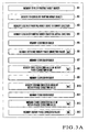
- the CPU 1 of the drive control device 100 of the offset sheet-fed printing press reads out the type of the printing target object from the printing target object type setter 10 and stores it in the memory M1 (steps S1 and S2 in Fig. 5A ), reads out the thickness of the printing target object from the printing target object thickness setter 11 and stores it in the memory M2 (steps S3 and S4), reads out the length of the printing target object in the convey direction from the setter 12 for the length of the printing target object in the convey direction and stores it in the memory M3 (steps S5 and S6), and reads out the length of the printing target object in the lateral direction from the setter 13 for the length of the printing target object in the lateral direction and stores it in the memory M4 (steps S7 and S8).
- the operator When starting printing, the operator turns on the synchronous operation switch 4 to command synchronous operation of the offset sheet-fed printing press and feeder. The operator also turns on the offset sheet-fed printing press drive switch 5 to command start of printing.
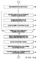
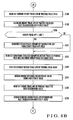
- step S9 Upon confirmation of the ON states of the synchronous operation switch 4 and of the offset sheet-fed printing press drive switch 5 (YES in step S9, YES in step S10), the CPU 1 advances to step S11 ( Fig. 5B ) and reads out the conversion table for converting the type of the printing object target into the rotary phase correction value of the feeder from the memory M5.
- the conversion table for converting the type of the printing target object into the rotary phase correction value of the feeder is a table that shows the relationship between the type of the printing target object and the rotary phase correction value of the feeder, and is determined through repeated experiments.
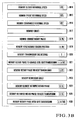
- the CPU 1 then reads out the type of the printing target object from the memory M1 (step S12), obtains the rotary phase correction value of the feeder corresponding to the type of the printing target object using the conversion table for converting the type of the printing target object into the rotary phase correction value of the feeder, which table is read out from the memory M5, and stores the obtained value in the memory M6 as a reference rotary phase correction value ha0 of the feeder which is specific to the printing target object (step S13).
- the CPU 1 reads out the type of the printing target object from the memory M1 (step S14) and the conversion table for converting the thickness of the printing target object into the rotary phase correction value of the feeder corresponding to the type of the printing target object from the memory M7 (step S15).
- the memory M7 stores the table showing the relationship between the thickness of the printing target object and the rotary phase correction value of the feeder of each printing target object type. This table is also determined through repeated experiments.
- the CPU 1 reads out the thickness of the printing target object from the memory M2 (step S16), obtains the rotary phase correction value of the feeder corresponding to the thickness of the printing target object using the conversion table for converting the thickness of the printing target object into the rotary phase correction value of the feeder corresponding to the type of the printing target object, which table is read out from the memory M7, and stores the obtained value in the memory M8 as a first correction value ha1 of the rotary phase correction value of the feeder which is specific to the printing target object (step S17).
- the CPU 1 reads out the type of the printing target object from the memory M1 (step S18) and the conversion table for converting the length of the printing target object in the convey direction into the rotary phase correction value of the feeder corresponding to the type of the printing target object from the memory M9 (step S19).
- the memory M9 stores the table showing the relationship between the length of the printing target object in the convey direction and the rotary phase correction value of the feeder of each printing target object type. This table is also determined through repeated experiments.
- the CPU 1 reads out the length of the printing target object in the convey direction from the memory M3 (step S20), obtains the rotary phase correction value of the feeder corresponding to the length of the printing target object in the convey direction using the conversion table for converting the length of the printing target object in the convey direction into the rotary phase correction value of the feeder corresponding to the type of the printing target object, which table is read out from the memory M9, and stores the obtained value in the memory M10 as a second correction value ha2 of the rotary phase correction value of the feeder which is specific to the printing target object (step S21 in Fig. 5C ).
- the CPU 1 reads out the type of the printing target object from the memory M1 (step S22) and the conversion table for converting the length of the printing target object in the lateral direction into the rotary phase correction value of the feeder corresponding to the type of the printing target object from the memory M11 (step S23).
- the memory M11 stores the table showing the relationship between the length of the printing target object in the lateral direction and the rotary phase correction value of the feeder of each printing target object type. This table is also determined through repeated experiments.
- the CPU 1 reads out the length of the printing target object in the lateral direction from the memory M4 (step S24), obtains the rotary phase correction value of the feeder corresponding to the length of the printing target object in the lateral direction using the conversion table for converting the length of the printing target object in the lateral direction into the rotary phase correction value of the feeder corresponding to the type of the printing target object, which table is read out from the memory M11, and stores the obtained value in the memory M12 as a third correction value ha3 of the rotary phase correction value of the feeder which is specific to the printing target object (step S25).
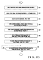
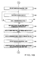
- the CPU 1 sends an actuation cancel signal to the prime motor brake circuit 28 of the offset sheet-fed printing press and the driving motor brake circuit 30 of the feeder (step S31 in Fig. 5D ) to turn off the prime motor brake 29 of the offset sheet-fed printing press and the driving motor brake 31 of the feeder.
- the CPU 1 then turns on a start signal for the prime motor driver 17 of the offset sheet-fed printing press (step S32), reads out a slower rotational speed VPL set in the memory M14 (step S33), and stores the slower rotational speed VPL in the memory M15 as a preset rotational speed VPS (step S34) and in the memory M16 as a commanded rotational speed VPC (step S35).
- the CPU 1 then outputs the commanded rotational speed VPC (slower rotational speed VPL) to the prime motor driver 17 of the offset sheet-fed printing press (step S36).
- VPC slower rotational speed
- VPL the prime motor driver 17 of the offset sheet-fed printing press
- the CPU 1 After outputting the commanded rotational speed VPC to the prime motor driver 17 of the offset sheet-fed printing press (step S36), the CPU 1 transmits an origin restoration start command to the drive control device 200 of the feeder (step S37).
- the CPU 51 of the drive control device 200 of the feeder receives it (step S402) and enables a start signal for the feeder driving motor driver 61 (step S403).
- the CPU 51 then reads out a slower rotational speed VFL set in the memory M51 (step S404), writes the readout slower rotational speed VFL in the memory M52 as a commanded rotational speed VFC (step S405), and outputs the commanded rotational speed VFC (slower rotational speed VFL) to the feeder driving motor driver 61 (step S406).
- the feeder driving motor 62 starts to rotate at the commanded rotational speed VFC, that is, the slower rotational speed VFL.
- the feeder origin position detection sensor 67 When the rotary position of the feeder driving motor 62 rotates at the slower rotational speed VFL to reach an origin position ⁇ F0 which is determined as a reference rotational angular position, the feeder origin position detection sensor 67 is turned on. When the feeder origin position detection sensor 67 is turned on (YES in step S407), the CPU 51 outputs a stop command to the feeder driving motor driver 61 (step S408). Thus, the feeder driving motor 62 stops at the origin position ⁇ F0. Simultaneously, the CPU 51 outputs an origin restoration completion signal to the drive control device 100 of the offset sheet-fed printing press (step S409). Fig. 15A shows this state.
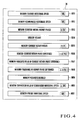
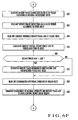
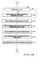
- the CPU 1 of the drive control device 100 of the offset sheet-fed printing press receives it (step S39 in Fig. 6A ), reads the count of the rotary phase detection counter 25 of the offset sheet-fed printing press, and stores the count in the memory M17 (step S40).
- the CPU 1 calculates a current rotary phase ⁇ PR of the offset sheet-fed printing press from the count of the rotary phase detection counter 25 (step S41).
- the CPU 1 then reads out a synchronous standby position ⁇ P0 of the offset sheet-fed printing press which is set in the memory M19 to correspond to the origin position ⁇ F0 of the feeder (step S42).
- the CPU 1 repeats the processes of steps S40 to S43 until the current rotary phase ⁇ PR of the offset sheet-fed printing press reaches the synchronous standby position ⁇ P0 (YES in step S43).
- step S43 if the current rotary phase ⁇ PR of the offset sheet-fed printing press reaches the synchronous standby position ⁇ P0 (YES in step S43), the CPU 1 transmits a synchronous origin alignment start command to the drive control device 200 of the feeder (step S44).
- Fig. 15B shows this state.
- step S410 When the synchronous origin alignment start command is sent from the drive control device 100 of the offset sheet-fed printing press (YES in step S410, Fig. 12A ), the CPU 51 of the drive control device 200 of the feeder receives it (step S411) and waits for the commanded rotational speed and current virtual rotary phase (to be described later) of the feeder to be sent from the drive control device 100 of the offset sheet-fed printing press (step S412).
- the CPU 1 of the drive control device 100 of the offset sheet-fed printing press After transmitting the synchronous origin alignment start command to the drive control device 200 (step S44), the CPU 1 of the drive control device 100 of the offset sheet-fed printing press reads out the slower rotational speed VPL from the memory M14 (step S45), writes the readout slower rotational speed VPL in the memory M15 as the preset rotational speed VPS (step S46) and in the memory M16 as the commanded rotational speed VPC (step S47).
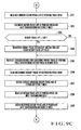
- the CPU 1 outputs a reset signal and enable signal to the internal clock counter 32 for counting the lapse time (step S48 in Fig. 6B ), and stops the reset signal for the internal clock counter 32 (step S49).
- the internal clock counter 32 starts counting the clock pulse from zero.
- a time interval T is set in the memory M20 which the commanded rotational speed and current virtual rotary phase of the feeder are transmitted to the drive control device 200 of the feeder.
- the CPU 1 reads out the transmission time interval T from the memory M20 (step S50).
- the CPU 1 also reads the count of the internal clock counter 32 (step S51).
- the CPU 1 obtains the commanded rotational speed of the feeder and the current virtual rotary phase of the feeder which are necessary for synchronous origin alignment of the offset sheet-fed printing press and feeder.
- the commanded rotational speed of the feeder is a rotational speed to be commanded to the feeder so that the feeder rotates in response to rotation of the offset sheet-fed printing press, and is obtained from the processes of steps S55 to S73.
- the current virtual rotary phase of the feeder is an assumption value of the rotary phase of the feeder at the current time point of calculation, and is determined by considering the fluctuation of the rotary phase according to the printing conditions such as the rotational speed as well.
- the current virtual rotary phase of the feeder is obtained from the processes of steps S74 to S85. This will be described hereinafter in more detail.
- the CPU 1 reads the count of the rotary phase detection counter 25 of the offset sheet-fed printing press and stores it in the memory M17 (step S55).
- the CPU 1 calculates the current rotary phase ⁇ PR of the offset sheet-fed printing press from the count of the rotary phase detection counter 25 of the offset sheet-fed printing press and stores it in the memory M18 (step S56 in Fig. 6C ).
- the CPU 1 reads out the commanded rotational speed VPC (slower rotational speed VPL) of the offset sheet-fed printing press from the memory M16 (step S57) and the time interval T of transmission to the drive control device 200 of the feeder from the memory M20 (step S58).
- the CPU 1 multiplies the commanded rotational speed VPC by the transmission time interval T, calculates a rotary phase ⁇ PRT for which the offset sheet-fed printing press advances until the next transmission, and stores the rotary phase ⁇ PRT in the memory M21 (step S59).
- the CPU 1 reads out the current rotary phase ⁇ PR of the offset sheet-fed printing press from the memory M18 (step S60), obtains a rotary phase ⁇ PT of the offset sheet-fed printing press for the next transmission by adding the rotary phase ⁇ PRT, for which the offset sheet-fed printing press advances until the next transmission, to the current rotary phase ⁇ PR of the offset sheet-fed printing press, and stores the obtained rotary phase ⁇ PT in the memory M22 (step S61).
- step S62 If the rotary phase ⁇ PT of the offset sheet-fed printing press for the next transmission is equal to or more than 360° (YES in step S62), the CPU 1 subtracts 360° from the rotary phase ⁇ PT of the offset sheet-fed printing press for the next transmission, and overwrites the obtained rotary phase in the memory M22 as the rotary phase ⁇ PT of the offset sheet-fed printing press for the next transmission (step S63).
- the conversion table for converting the rotary phase of the offset sheet-fed printing press into the reference rotary phase of the feeder is a table showing the relationship between the rotary phase of the offset sheet-fed printing press and the reference rotary phase of the feeder, and is determined in advance to exhibit the relationship as shown in Fig. 17 .
- the rotary phase of the offset sheet-fed printing press and the reference rotary phase of the feeder do not establish a linear relationship, but exhibit a characteristic curve in which a change in rotary phase of the feeder accelerates or decelerates with respect to a change in rotary phase of the offset sheet-fed printing press. More specifically, according to this relationship, a change in rotary phase of the feeder is small at the start or end of sheet feed, and is large at the intermediate portion of sheet feed, thus accelerating and decelerating the change of the rotary phase (the sheet convey speed) of the feeder. According to this embodiment, this relationship is stored in the memory M23 in the form of the conversion table for converting the rotary phase of the offset sheet-fed printing press into the reference rotary phase of the feeder.
- the CPU 1 After reading out the conversion table for converting the rotary phase of the offset sheet-fed printing press into the reference rotary phase of the feeder from the memory M23 (step S64), the CPU 1 reads out the current rotary phase ⁇ PR of the offset sheet-fed printing press from the memory M18 (step S65). The CPU 1 then obtains a current reference rotary phase ⁇ FA of the feeder corresponding to the current rotary phase ⁇ PR of the offset sheet-fed printing press using the conversion table for converting the rotary phase of the offset sheet-fed printing press into the reference rotary phase of the feeder, which table is read out from the memory M23 (see Fig. 16A ), and stores it in the memory M24 (step S66).
- the reference rotary phase of the feeder which is converted from the rotary phase of the offset sheet-fed printing press using the above table serves as the reference value in calculation of the rotary phase of the feeder.
- the CPU 1 also reads out the rotary phase ⁇ PT of the offset sheet-fed printing press for the next transmission from the memory M22 (step S67), obtains a reference rotary phase ⁇ FB of the feeder for the next transmission corresponding to the rotary phase ⁇ PT of the offset sheet-fed printing press for the next transmission using the conversion table for converting the rotary phase of the offset sheet-fed printing press into the reference rotary phase of the feeder, which table is read out from the memory M23 (see Fig. 16B ), and stores the obtained reference rotary phase ⁇ FB in the memory M25 (step S68).
- the CPU 1 checks whether or not the rotary phase adjustment value (manual adjustment value) of the feeder is input from the feeder rotary phase setter 14 (step S74). If the rotary phase adjustment value of the feeder is input (YES in step S74), the CPU 1 reads out the rotary phase adjustment value of the feeder from the feeder rotary phase adjustment value setter 14 and stores it in the memory M28 (step S75). In this example, assume that the rotary phase adjustment value of the feeder is not yet input from the feeder rotary phase adjustment value setter 14, and that the rotary phase adjustment value of the feeder in the memory M28 is zero (initial value).
- the CPU 1 reads out the rotary phase adjustment value of the feeder from the memory M28 (step S76), calculates a manually adjusted rotary phase correction value HC of the feeder from the readout rotary phase adjustment value of the feeder, and stores the rotary phase correction value HC in the memory M29 (step S77).
- the manually adjusted rotary phase correction value HC of the feeder is also zero.
- the conversion table for converting the rotational speed of the prime motor of the offset sheet-fed printing press into the rotary phase correction value of the feeder is a table showing the relationship between the rotational speed of the prime motor of the offset sheet-fed printing press and the rotary phase correction value of the feeder, and is determined through repeated experiments.
- the CPU 1 reads out the commanded rotational speed VPC (slower rotational speed VPL) of the offset sheet-fed printing press from the memory M16 (step S79), obtains the rotary phase correction value of the feeder corresponding to the commanded rotational speed VPC of the offset sheet-fed printing press using the conversion table for converting the rotational speed of the prime motor of the offset sheet-fed printing press into the rotary phase correction value of the feeder, which table is read out from the memory M30, and stores the obtained rotary phase correction value in the memory M31 as a speed-specific rotary phase correction value HB of the feeder (step S80).
- VPC slower rotational speed VPL
- the CPU 1 reads out a rotary phase correction value HA of the feeder which is specific to the printing target object from the memory M13 (step S81), the manually adjusted rotary phase correction value HC of the feeder from the memory M29 (step S82 in Fig. 6F ), the speed-specific rotary phase correction value HB of the feeder from the memory M31 (step S83), and the current reference rotary phase ⁇ FA of the feeder from the memory M24 (step S84).
- step S86 the CPU 1 subtracts 360° from the current virtual rotary phase ⁇ FA' of the feeder, and overwrites the obtained rotary phase in the memory M32 as the current virtual rotary phase ⁇ FA' of the feeder (step S87).
- the CPU 1 reads out the commanded rotational speed VFC of the feeder from the memory M27 (step S88) and transmits the commanded rotational speed VFC and current virtual rotary phase ⁇ FA' of the feeder to the drive control device 200 of the feeder (step S89; see Fig. 15C ). After transmitting the commanded rotational speed VFC and current virtual rotary phase ⁇ FA' of the feeder, the CPU 1 returns to the process of step S48 ( Fig. 6B ).
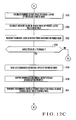
- the CPU 51 reads the count of the feeder rotary phase detection counter 66 and stores it in the memory M54 (step S414).
- the CPU 51 calculates a current rotary phase ⁇ FR of the feeder from this count and stores it in the memory M55 (step S415).
- the CPU 51 then reads out the current virtual rotary phase ⁇ FA' of the feeder which is transmitted from the CPU 51 of the drive control device 200 of the feeder and stored in the memory M53 (step S416).
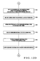
- step S417 If the current virtual rotary phase ⁇ FA' of the feeder satisfies ⁇ FA' > 340° (YES in step S417, Fig. 12B ) and the current rotary phase ⁇ FR of the feeder satisfies ⁇ FR ⁇ 20° (step S418, YES in S419), the CPU 51 adds 360° to the current rotary phase ⁇ FR of the feeder, and overwrites the obtained rotary phase in the memory M55 as the current rotary phase ⁇ FR of the feeder (step S420).
- step S421 If the current virtual rotary phase ⁇ FA' of the feeder satisfies ⁇ FA' ⁇ 20° (YES in step S421) and the current rotary phase ⁇ FR of the feeder satisfies ⁇ FR > 340° (step S422, YES in S423), the CPU 51 adds 360° to the current virtual rotary phase ⁇ FA of the feeder, and overwrites the obtained rotary phase in the memory M53 as the current virtual rotary phase ⁇ FA' of the feeder (step S424).
- the CPU 51 subtracts the current rotary phase ⁇ FR of the feeder from the current virtual rotary phase ⁇ FA' of the feeder to obtain a current rotary phase difference ⁇ FRA' of the feeder (see Fig. 16D ), and stores the obtained current rotary phase difference ⁇ FRA' of the feeder in the memory M56 (step S425 in Fig. 12C ).
- the CPU 51 also obtains the absolute value of the current rotary phase difference ⁇ FRA' of the feeder from the current rotary phase difference ⁇ FRA' of the feeder and stores it in the memory M57 (step S426).
- the CPU 51 then reads out a tolerance ⁇ Fth of the rotary phase difference of the feeder which is set in the memory M58 (step S427) and compares it with the absolute value of the current rotary phase difference ⁇ FRA' of the feeder (step S428).
- the CPU 51 reads out the conversion table for converting the current rotary phase difference of the feeder into the correction value of the commanded rotational speed from the memory M59 (step S432 in Fig. 12D ) and the current rotary phase difference ⁇ FRA' of the feeder from the memory M56 (step S433).
- the CPU 51 obtains a correction value ⁇ VFC of the commanded rotational speed corresponding to the current rotary phase difference ⁇ FRA' of the feeder using the conversion table for converting the current rotary phase difference of the feeder into the correction value of the commanded rotational speed, and stores it in the memory M60 (step S434).
- the CPU 51 reads out the commanded rotational speed VFC of the feeder from the memory M52 (step S435), adds the correction value ⁇ VFC of the commanded rotational speed of the feeder to the commanded rotational speed VFC of the feeder, overwrites the obtained rotational speed in the memory M52 as the commanded rotational speed VFC (step S436), and outputs the commanded rotational speed VFC to the feeder driving motor driver 61 (step S437).
- the feeder driving motor 62 starts to rotate at the corrected commanded rotational speed VFC.
- the CPU 1 of the drive control device 100 of the offset sheet-fed printing press transmits the commanded rotational speed VFC and current virtual rotary phase ⁇ FA' of the feeder to the drive control device 200 of the feeder. If a synchronous origin alignment completion signal (to be described later) is not sent back from the drive control device 200 of the feeder until the next transmission time interval T elapses (NO in steps S52, S53, and S54 in Fig. 6B ), the CPU 1 repeats the processes of steps S55 ( Fig. 6B ) to S89 ( Fig. 6F ), to repeatedly transmit the commanded rotational speed VFC and current virtual rotary phase ⁇ FA' of the feeder to the drive control device 200 of the feeder.
- step S413 Every time the commanded rotational speed VFC and current virtual rotary phase ⁇ FA' of the feeder are transmitted from the drive control device 100 of the offset sheet-fed printing press (YES in step S412, Fig. 12A ), the CPU 51 repeats the processes from step S413.
- the CPU 51 reads out the commanded rotational speed VFC of the feeder from the memory M52 (step S429) and outputs it to the feeder driving motor driver 61 (step S430). The CPU 51 then transmits the synchronous origin alignment completion signal to the drive control device 100 of the offset sheet-fed printing press (step S431). Fig. 15D shows this state.
- the CPU 1 of the drive control device 100 of the offset sheet-fed printing press receives it from the drive control device 200 of the feeder (step S90 in Fig. 6G ), reads out the time interval T of transmission to the drive control device 200 of the feeder from the memory M20 (step S91), and reads the count of the internal clock counter 32 (step S92).
- the CPU 1 advances to step S94 and performs the processes of steps S94 ( Fig. 6G ) to S128 ( Fig.
- the CPU 1 reads out the commanded rotational speed VPC (slower rotational speed VPL) of the offset sheet-fed printing press from the memory M16 (step S129), outputs the commanded rotational speed VPC to the prime motor driver 17 of the offset sheet-fed printing press (step S130), and writes the commanded rotational speed VPC in the memory M33 as a previous commanded rotational speed VPCold of the offset sheet-fed printing press (step S131).
- VPC slower rotational speed VPL
- the CPU 1 outputs a reset signal and enable signal to the internal clock counter 32 (step S132 in Fig. 7A ) and stops outputting the reset signal to the internal clock counter 32 (step S133), so that the internal clock counter 32 starts counting clock pulses from zero.
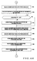
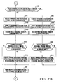
- the CPU 1 checks whether or not a rotational speed VP is input to the rotational speed setter 15 (step S134). If the rotational speed VP is input (YES in step S134), the CPU 1 reads it from the rotational speed setter 15 and stores it in the memory M15 as the preset rotational speed VPS (step S135). In this example, assume that a speed of final printing is input as the rotational speed VP. Hence, in response to YES in step S134, the CPU 1 advances to step S135 and stores the speed of final printing in the memory M15 as the preset rotational speed VPS.
- the CPU 1 reads out the preset rotational speed VPS of the offset sheet-fed printing press from the memory M15 (step S136) and the previous commanded rotational speed VPCold of the offset sheet-fed printing press from the memory M33 (step S137), and compares the former with the latter (step S138).
- the previous commanded rotational speed VPCold is the slower rotational speed VPL
- the preset rotational speed VPS is larger than the previous commanded rotational speed VPCold (NO in step S138, YES in step S140, Fig. 7B ).
- the CPU 1 reads out a rotational speed modification value ⁇ for acceleration from the memory M34 (step S141), adds it to the previous commanded rotational speed VPCold, and writes the addition result in the memory M36 as a modified commanded rotational speed VPCnew (step S142a).
- the CPU 1 then reads out the preset rotational speed VPS of the offset sheet-fed printing press from the memory M15 (step S142b).
- the CPU 1 rewrites the modified commanded rotational speed VPCnew for the preset rotational speed VPS of the offset sheet-fed printing press (step S142d). The CPU 1 then rewrites the commanded rotational speed VPC in the memory M16 for the modified commanded rotational speed VPCnew (step S147).
- the CPU 1 reads out the time interval T of transmission to the drive control device 200 of the feeder from the memory M20 (step S148 in Fig. 7C ), and reads the count of the internal clock counter 32 (step S149).
- the CPU 1 advances to step S151.
- the CPU 1 performs the processes of steps S151 ( Fig. 7C ) to S185 ( Fig. 7G ) similar to those of steps S55 ( Fig. 6B ) to S89 ( Fig. 6F ) to transmit the commanded rotational speed VFC and current virtual rotary phase ⁇ FA' of the feeder to the drive control device 200 of the feeder.
- the new commanded rotational speed VPC VPCnew which is rewritten in step S147 is employed.
- step S438, Fig. 13A When the commanded rotational speed VFC and current virtual rotary phase ⁇ FA' of the feeder are transmitted from the drive control device 100 of the offset sheet-fed printing press (YES in step S438, Fig. 13A ), the CPU 51 of the drive control device 200 of the feeder performs the processes of steps S439 ( Fig. 13A ) to S462 ( Fig. 13C ) similar to those of steps S413 ( Fig. 12A ) to S437 ( Fig. 12D ) described above to control the rotation of the feeder driving motor 62. In these processes, no step corresponding to step S431 exists after step S456, and no synchronous alignment completion signal is transmitted.
- the CPU 1 of the drive control device 100 of the offset sheet-fed printing press reads out the commanded rotational speed VPC (VPCnew) of the offset sheet-fed printing press from the memory M16 (step S186 in Fig. 7G ), outputs the commanded rotational speed VPC to the prime motor driver 17 of the offset sheet-fed printing press (step S187), and writes the commanded rotational speed VPC in the memory M33 as the previous commanded rotational speed VPCold of the offset sheet-fed printing press (step S188). If NO in step S189, the CPU 1 returns to step S132 ( Fig. 7A ) and repeats the same processes.
- the speed of the prime motor 18 of the offset sheet-fed printing press and that of the driving motor 62 of the feeder increase while maintaining the relationship that the absolute value of the current rotary phase difference ⁇ FRA' of the feeder is equal to or less than the tolerance ⁇ Fth of the rotary phase difference of the feeder.
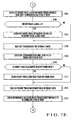
- step S143 the CPU 1 reads out a rotational speed modification value ⁇ for deceleration from the memory M35 (step S143).
- the CPU 1 subtracts the rotational speed modification value ⁇ for deceleration from the previous commanded rotational speed VPCold, and writes the subtraction result in the memory M36 as the modified commanded rotational speed VPCnew (step S144a).
- the CPU 1 then reads out the preset rotational speed VPS of the offset sheet-fed printing press from the memory M15 (step S144b).
- step S145 If the modified commanded rotational speed VPCnew is smaller than the preset rotational speed VPS (YES in step S145), the CPU 1 rewrites the modified commanded rotational speed VPCnew for the preset rotational speed VPS of the offset sheet-fed printing press (step S146). The CPU 1 then advances to step S147, and rewrites the commanded rotational speed VPC in the memory M16 for the modified commanded rotational speed VPCnew.
- the CPU 1 reads out the time interval T of transmission to the drive control device 200 of the feeder from the memory M20 (step S148 in Fig. 7C ), and reads the count of the internal clock counter 32 (step S149).
- the CPU 1 advances to step S151.
- the CPU 1 performs the processes of steps S152 to S185 described above to transmit the commanded rotational speed VFC and current virtual rotary phase ⁇ FA' of the feeder to the drive control device 200 of the feeder.
- the CPU 51 of the drive control device 200 of the feeder performs the processes of steps S439 to S462 described above to control the rotation of the driving motor 62 of the feeder.
- the CPU 1 of the drive control device 100 of the offset sheet-fed printing press reads out the commanded rotational speed VPC (VPCnew) of the offset sheet-fed printing press from the memory M16 (step S186 in Fig. 7G ), outputs the commanded rotational speed VPC to the prime motor driver 17 of the offset sheet-fed printing press (step S187), and writes the commanded rotational speed VPC in the memory M33 as the previous commanded rotational speed VPCold of the offset sheet-fed printing press (step S188).
- the CPU 1 returns to step S132 ( Fig. 7A ), and repeats the same processes.
- the speed of the prime motor 18 of the offset sheet-fed printing press and that of the driving motor 62 of the feeder decrease while maintaining the relationship of ⁇ FRA' ⁇ ⁇ Fth.
- step S139 the CPU 1 advances to the process of step S148 ( Fig. 7C ), and performs the processes of steps S149 to S188. If NO in step S189, the CPU 1 returns to step S132 ( Fig. 7A ), and repeats the same processes.
- the prime motor 18 of the offset sheet-fed printing press and the driving motor 62 of the feeder continue driving at the speed of final printing (normal printing speed) while maintaining the relationship of ⁇ FRA' ⁇ ⁇ Fth.
- the CPU 1 adds the rotary phase correction value HA of the feeder which is specific to the printing target object, the speed-specific rotary phase correction value HB of the feeder, and the manually adjusted rotary phase correction value HC of the feeder to the current reference rotary phase ⁇ FA of the feeder to obtain the current virtual rotary phase ⁇ FA' of the feeder.
- the rotary phase correction value HA of the feeder which is specific to the printing target object is automatically obtained from the size, thickness, and quality of the sheet, and the speed-specific rotary phase correction value HB of the feeder is automatically obtained from the speed of the printing press.
- the rotary phase of the feeder is automatically adjusted. Therefore, the operator only needs to input these printing conditions at the start of printing, and need not adjust the rotary phase of the feeder in accordance with the printing conditions. This reduces the load to the operator and improves the register accuracy.
- the rotary phase of the feeder can be adjusted manually as well. Manual adjustment can be performed freely without stopping the operation of the printing press.
- the operator wishes to manually adjust the rotary phase of the feeder, in the drive control device 100 of the offset sheet-fed printing press, he inputs the rotary phase adjustment value (manual adjustment value) of the feeder to the feeder rotary phase adjustment value setter 14.
- the CPU 1 obtains the manually adjusted rotary phase correction value HC of the feeder from the rotary phase adjustment value of the feeder and uses it to calculate the current virtual rotary phase ⁇ FA' of the feeder.
- the rotary phase of the feeder is adjusted without stopping the operation of the printing press. This reduces the down time of the printing press, improves the operation efficiency, and reduces the load to the operator.
- the rotary phase of the feeder can be adjusted easily within a short period of time without stopping the operation of the printing press.
- the rotary phase of the feeder is automatically adjusted in accordance with the printing conditions such as the speed of the printing press (speed of final printing), and the size, thickness and quality of the sheet. Every time the printing conditions are changed, the rotary phase of the feeder need not be adjusted in accordance with the new printing conditions.
- the second conventional problem can be solved.
- step S189 Fig. 7G
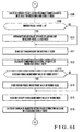
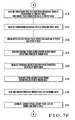
- the CPU 1 of the drive control device 100 of the offset sheet-fed printing press advances to step S231 ( Fig. 9A ), and resets the preset rotational speed VPS stored in the memory M15 to zero.
- the CPU 1 outputs a reset signal and enable signal to the internal clock counter 32 (step S232) and stops the reset signal for the internal clock counter 32 (step S233), so that the internal clock counter 32 starts counting clock pulses from zero.
- the CPU 1 reads out the previous commanded rotational speed VPCold of the offset sheet-fed printing press from the memory M33 (step S234).
- the CPU 1 reads out the rotational speed modification value ⁇ for deceleration from the memory M35 (step S236).
- the CPU 1 then subtracts the rotational speed modification value ⁇ for deceleration from the previous commanded rotational speed VPCold, and writes the subtraction result in the memory M36 as the modified commanded rotational speed VPCnew (step S237).
- step S2308 If the modified commanded rotational speed VPCnew is less than zero (YES in step S238), the CPU 1 resets it to zero (step S239) and rewrites the commanded rotational speed VPC in the memory M16 for the modified commanded rotational speed VPCnew (step S240). The CPU 1 also writes the modified commanded rotational speed VPCnew in the memory M33 as VPCold (step S241).
- the CPU 1 reads out the time interval T of transmission to the drive control device 200 of the feeder from the memory M20 (step S243 in Fig. 9B ) and reads the count of the internal clock counter 32 (step S244).
- the CPU 1 advances to step S246.
- the CPU 1 performs the processes of steps S246 ( Fig. 9B ) to S280 ( Fig. 9F ) similar to those of steps S55 ( Fig. 6B ) to S89 ( Fig. 6F ) to transmit the commanded rotational speed VFC and current virtual rotary phase ⁇ FA' of the feeder to the drive control device 200 of the feeder.
- the new commanded rotational speed VPC VPCnew which is rewritten in step S240 is employed.
- the CPU 1 reads out the commanded rotational speed VPC (VPCnew) of the offset sheet-fed printing press from the memory M16 (step S281 in Fig. 9F ), outputs the commanded rotational speed VPC to the prime motor driver 17 of the offset sheet-fed printing press (step S282), and writes the commanded rotational speed VPC in the memory M33 as the previous commanded rotational speed VPCold of the offset sheet-fed printing press (step S283).
- the CPU 1 reads an output from the F/V converter 20 connected to the prime motor 18 of the offset sheet-fed printing press and an output from the F/V converter 23 connected to the driving motor of the feeder (step S284 in Fig. 9G ), and obtains the current rotational speeds of the offset sheet-fed printing press and feeder from the outputs from the F/V converters 20 and 23 (step S285).
- the CPU 1 Upon confirmation of the fact that the current rotational speeds of the offset sheet-fed printing press and feeder are not zero (NO in step S286), the CPU 1 returns to step S232 ( Fig. 9A ), and repeats the same processes.
- the speed of the prime motor 18 of the offset sheet-fed printing press and that of the driving motor 62 of the feeder decrease while maintaining the relationship that the absolute value of the current rotary phase difference ⁇ FRA' of the feeder is equal to or less than the tolerance ⁇ Fth of the rotary phase difference of the feeder.
- step S284 in Fig. 9G the CPU 1 also reads the outputs from the F/V converters 20 and 23 (step S284 in Fig. 9G ), and obtains the current rotational speeds of the offset sheet-fed printing press and feeder from them (step S285).
- step S286 the CPU 1 transmits a synchronous operation stop command to the drive control device 200 of the feeder (step S287).
- the CPU 51 of the drive control device 200 of the feeder receives it from the drive control device 100 of the offset sheet-fed printing press (step S464), and transmits it to the drive control device 100 of the offset sheet-fed printing press (step S465). Also, the CPU 1 disables the start signal for the feeder driving motor driver 61 (step S466) and outputs an actuation signal to the feeder driving motor brake circuit 68 (step S467) to turn on the feeder driving motor brake 69.
- the CPU 1 of the drive control device 100 of the offset sheet-fed printing press receives it from the drive control device 200 of the feeder (step S289), disables the start signal to the prime motor 18 of the offset sheet-fed printing press (step S290), and outputs an actuation signal to the prime motor brake circuit 28 of the offset sheet-fed printing press (step S291) to turn on the prime motor brake 29 of the offset sheet-fed printing press.
- step S292 After stopping the printing press, when the synchronous operation switch 4 is turned off (YES in step S292), the CPU 1 returns to the process of step S1 ( Fig. 5A ). After the printing press is stopped, when the offset sheet-fed printing press drive switch 5 is turned on (YES in step S293), the CPU 1 returns to the process of step S11 ( Fig. 5A ).
- the drive control device 200 of the feeder sends the synchronous origin alignment completion signal to the drive control device 100 of the offset sheet-fed printing press.
- the operator may notice a setting mistake in, e.g., the type or thickness of the printing target object and wish to suspend the offset sheet-fed printing press during operation.
- step S54 the CPU 1 of the drive control device 100 of the offset sheet-fed printing press advances to step S190 ( Fig. 8A ), and reads out the time interval T of transmission to the drive control device 200 of the feeder from the memory M20.
- the CPU 1 then reads the count of the internal clock counter 32 (step S191).
- the CPU 1 advances to step S193, and performs the processes of steps S193 ( Fig. 8A ) to S230 ( Fig. 8E ) which are similar to those of steps S94 ( Fig.
- step S9 When the synchronous operation switch 4 is turned off and the offset sheet-fed printing press drive switch 5 is turned on, if NO in step S9 ( Fig. 5 ), the CPU 1 of the drive control device 100 of the offset sheet-fed printing press advances to step S294 ( Fig. 10 ), loads the rotational speed VP of the printing press input from the rotational speed setter 15, and stores the rotational speed VP in the memory M15 as the preset rotational speed VPS (step S295).
- the CPU 1 Upon confirmation of the fact that the offset sheet-fed printing press drive switch 5 is ON (YES in step S296), the CPU 1 sends an actuation cancel signal to the prime motor brake circuit 28 of the offset sheet-fed printing press (step S297) to turn off the prime motor brake 29 of the offset sheet-fed printing press, and writes the preset rotational speed VPS in the memory M16 as the commanded rotational speed VPC (step S298).
- the CPU 1 also reads out the commanded rotational speed VPC written in the memory M16 (step S299) and outputs it to the prime motor driver 17 of the offset sheet-fed printing press (step S300).
- the prime motor 18 of the offset sheet-fed printing press rotates at the commanded rotational speed VPC, that is, the rotational speed VP input from the rotational speed setter 15, so that the printing press main body operates in a standalone state.
- step S301 When the printing press stop switch 6 is turned on (YES in step S301), the CPU 1 outputs a stop command for the prime motor driver 17 of the offset sheet-fed printing press (step S302), disables a start signal for the prime motor driver 17 of the offset sheet-fed printing press (step S303), and outputs an actuation signal to the prime motor brake circuit 28 of the offset sheet-fed printing press (step S304).
- the prime motor brake 29 of the offset sheet-fed printing press is turned on to stop the prime motor 18 of the offset sheet-fed printing press.
- step S470 When the feeder standalone drive switch 54 is turned on (YES in step S470), the CPU 51 sends an actuation cancel signal to the feeder driving motor brake circuit 68 (step S471) to turn off the feeder driving motor brake 69.
- the CPU 51 writes the preset rotational speed VFS in the memory 52 as the commanded rotational speed VFC (step S472), reads out the commanded rotational speed VPC written in the memory M52 (step S473) and outputs it to the feeder driving motor driver 61 (step S474).
- the feeder driving motor 62 rotates at the commanded rotational speed VFC, that is, the rotational speed VF input from the feeder rotational speed setter 59, so that the feeder operates in a standalone state.
- step S475 When the feeder stop switch 55 is turned on (YES in step S475), the CPU 51 outputs a stop command for the feeder driving motor driver 61 (step S475), turns off a start signal for the feeder driving motor driver 61 (step S477), and outputs an actuation signal to the feeder driving motor brake circuit 68 (step S478).
- the feeder driving motor brake 69 is turned on to stop the feeder driving motor 62.
- the present invention is not limited to a sheet-fed rotary printing press.
- the offset sheet-fed printing press corresponds to a sheet processing device which processes a sheet
- the feeder corresponds to a sheet feed device which feeds the sheet.
- the present invention can be applied to any sheet processing machine as far as it comprises such a sheet processing device and sheet feed device.
- the rotary phase of the driving motor 62 of the feeder with respect to the rotary phase of the printing press main body of the offset sheet-fed printing press is adjusted.
- the rotary phase of the prime motor 18 of the offset sheet-fed printing press with respect to the rotary phase of the feeder driving motor 62 may be adjusted.
- printing misregistration or the like may occur.
- this embodiment is exemplified by a feeder (feed device) which employs conveyor tapes
- the present invention can also be similarly applied to a roll type feed device which does not employ conveyor tapes.
- slippage occurs only when a suction device feeds a sheet to a portion between a feed roller and feed roll.
- a table showing the relationship between the printing conditions and the correction value of the rotary phase may be determined considering the slip amount at this portion.
- the relationship between the rotary phase of the offset sheet-fed printing press and the reference rotary phase of the feeder is linear. Thus, the process is easier than in a feed device that employs conveyor tapes.
- printing conditions such as the type and thickness of the printing target object, the lengths of the printing target object in the convey direction and lateral direction, the rotational speed of the printing press, and the like are set.
- the printing conditions may be changed during printing. If the printing conditions are changed during printing, the rotary phase correction value HA of the feeder which is specific to the printing target object and the speed-specific rotary phase correction value HB of the feeder are calculated as values in accordance with the changed printing conditions, so that the rotary phase of the feeder is adjusted automatically.
- the manually adjusted rotary phase correction value HC of the feeder is stored in accordance with the printing conditions. Then, when printing is to be performed under the same printing conditions, the rotary phase correction value HC is employed from the beginning. This can save the operator manual operation.
- ⁇ FRA' ⁇ ⁇ Fth is maintained not only in ordinary printing speed but also during acceleration and deceleration.
- good printing products free from printing misregistration can be obtained throughout the entire period from the start of printing until the end of printing, so that the frequency of defective printing decreases.
- the driving shaft of the prime motor 18 is drive-connected to the driven shaft of the printing press main body of the offset sheet-fed printing press through a gear, and slippage hardly occurs between the two shafts.
- the rotary phase of the printing press main body of the offset sheet-fed printing press may be detected indirectly from a signal from the prime motor rotary encoder 21 of the offset sheet-fed printing press.
- a drive control system 300 of the sheet-fed rotary printing press comprises a synchronous operation unit 310 and rotary phase adjustment unit 320.
- the synchronous operation unit 310 operates the feeder driving motor 62 in synchronism with the rotary member of the offset sheet-fed printing press.
- the synchronous operation unit 310 performs the processes of steps S132 to S169, S182 to S189, and S438 to S462.
- the rotary phase adjustment unit 320 adjusts the rotary phase of the rotary member of the offset sheet-fed printing press and the rotary phase of the feeder driving motor 62 relative to each other. For example, the rotary phase adjustment unit 320 performs the processes of steps S11 to S30 and S170 to S181.
- the synchronous operation unit 310 comprises a first rotary phase detection unit 311 and rotational speed designation unit 312.
- the first rotary phase detection unit 311 detects the rotary phase of the rotary member of the offset sheet-fed printing press at a predetermined time interval T. For example, the first rotary phase detection unit 311 performs the processes of steps S148 to S152. Every time the rotary phase of the rotary member of the offset sheet-fed printing press is detected, the rotational speed designation unit 312 designates the rotary phase to the feeder driving motor 62 on the basis of the detected rotary phase. For example, the rotational speed designation unit 312 performs the processes of steps S132 to S147, S153 to S169, S182 to S185, and S438 to S462.
- the rotational speed designation unit 312 comprises a rotary phase calculation unit 313, table storage 314, rotary phase conversion unit 315, rotational speed calculation unit 316, second rotary phase detection unit 317, phase difference calculation unit 318, and rotational speed correction unit 319.
- the rotary phase calculation unit 313 calculates the rotary phase of the rotary member of the offset sheet-fed printing press which is obtained at a lapse of the predetermined time T since the rotary phase is detected. For example, the rotary phase calculation unit 313 performs the processes of steps S134 to S147 and S153 to S159.
- the table storage 314 stores a table as shown in Fig. 17 which shows the relationship between the rotary phase of the rotary member of the offset sheet-fed printing press and the rotary phase of the feeder driving motor 62.
- the rotary phase conversion unit 315 converts the rotary phase detected by the first rotary phase detection unit 311 and the rotary phase calculated by the rotary phase calculation unit 313 at the lapse of the predetermined period of time T, respectively, into the rotary phases of the feeder driving motor 62 by looking up the table stored in the table storage 314. For example, the rotary phase conversion unit 315 performs the processes of steps S160 to S164. Thus, the rotary phases of the feeder driving motor 62 at a certain time point and a lapse of the time T after that can be obtained.
- the rotational speed calculation unit 316 calculates the rotational speed of the feeder driving motor 62 from the two rotary phases converted by the rotary phase conversion unit 315, and the predetermined time T. For example, the rotational speed calculation unit 316 performs the processes of steps S165 to S169.
- the second rotary phase detection unit 317, phase difference calculation unit 318, and rotational speed correction unit 319 will be described later.
- the rotary phase adjustment unit 320 comprises a driving motor phase adjustment unit 321 which adjusts the rotary phase of the feeder driving motor 62 with respect to the rotary phase of the rotary member of the offset sheet-fed printing press.
- the rotary phase adjustment unit 320 performs the processes of steps S11 to S30 and S170 to S181.
- the driving motor phase adjustment unit 321 comprises a correction value calculation unit 322 and rotary phase correction unit 323.
- the correction value calculation unit 322 calculates the correction value of the rotary phase of the feeder driving motor 62 with respect to the rotary phase of the rotary member of the offset sheet-fed printing press in accordance with the printing conditions. For example, the correction value calculation unit 322 performs the processes of steps S11 to S30 and S170 to S176.
- the correction value calculation unit 322 includes a rotational speed-specific correction value calculation unit 322a, a sheet type-specific correction value calculation unit 322b, a sheet size-specific correction value calculation unit 322c, and a sheet thickness-specific correction value calculation unit 322d.
- the rotational speed-specific correction value calculation unit 322a calculates the correction value in accordance with the rotational speed of the prime motor (driving motor) 18 of the offset sheet-fed printing press, and performs the processes of, e.g., steps S174 to S176.
- the sheet type-specific correction value calculation unit 322b calculates the correction value in accordance with the sheet type, and performs the processes of, e.g., steps S11 to S13.
- the sheet size-specific correction value calculation unit 322c calculates the correction value in accordance with the sheet size, and performs the processes of, e.g., steps S18 to S25.
- the sheet thickness-specific correction value calculation unit 322d calculates the correction value in accordance with the sheet thickness, and performs the processes of, e.g., steps S14 to S17.
- the rotary phase correction unit 323 corrects the rotary phase of the feeder driving motor 62, obtained by conversion of the rotary phase detected by the first rotary phase detection unit 311 using the correction value calculated by the correction value calculation unit 322. For example, the rotary phase correction unit 323 performs the processes of steps S177 to S181.
- the second rotary phase detection unit 317 detects the actual rotary phase of the feeder driving motor 62.
- the second rotary phase detection unit 317 performs the processes of steps S440 and S441.
- the phase difference calculation unit 318 calculates the phase difference between the rotary phase corrected by the rotary phase correction unit 323 and the actual rotary phase detected by the second rotary phase detection unit 317.
- the phase difference calculation unit 318 performs the processes of steps S442 to S445.
- the rotational speed correction unit 319 corrects the rotational speed to be designated to the feeder driving motor 62 in accordance with the phase difference.
- the rotational speed correction unit 319 performs the processes of steps S452 to S454 and S457 and S462.
- the driving motor of the sheet processing device drives the sheet processing device
- the driving motor of the sheet feed device drives the sheet feed device.
- the sheet processing device is a printing press main body and the sheet feed device is a feed device
- the prime motor drives the printing press main body
- the standalone motor drives the feed device.
- the standalone motor provided independently of the prime motor that drives the printing press main body drives the feed device.
- the standalone motor is operated in synchronism with the printing press main body which is driven by the prime motor, so that the sheet is fed from the feed device to the printing press main body.
- the timing (the timing of transferring the sheet to the swing arm shaft pregripper) of feeding the sheet from the feed device to the printing press main body can be set at an appropriate timing without stopping the sheet processing machine, by adjusting the rotary phase of the rotary member of the printing press main body and the rotary phase of the standalone motor of the feed device relative to each other.
- the rotary phase of the driving motor of the sheet feed device with respect to the rotary phase of the rotary member of the sheet processing device may be adjusted, or the rotary phase of the driving motor of the sheet processing device with respect to the rotary phase of the driving motor of the sheet feed device may be adjusted.
- the correction value of the driving motor of the sheet feed device with respect to the rotary phase of the rotary member of the sheet processing device may be obtained in accordance with the printing conditions.
- the printing conditions such as the speed of the printing machine (e.g., the speed of final printing), the size, thickness and quality of the sheet, and the like are included as the sheet processing conditions, and the correction value of the rotary phase of the standalone motor corresponding to these sheet processing conditions is obtained. Then, at the start of printing, the correction value of the rotary phase corresponding to the given sheet processing conditions can be obtained automatically, so that the rotary phase is adjusted automatically.
- the automatically adjusted rotary phase can be adjusted later on manually without stopping the sheet processing machine.
- the rotary phase can be adjusted automatically by changing the sheet processing conditions during printing. Therefore, every time the sheet processing conditions are changed, the correction value of the rotary phase corresponding to the new sheet processing conditions can be obtained automatically, so that the rotary phase can be adjusted automatically.
Landscapes
- Engineering & Computer Science (AREA)
- Mechanical Engineering (AREA)
- Inking, Control Or Cleaning Of Printing Machines (AREA)
- Registering Or Overturning Sheets (AREA)
- Sheets, Magazines, And Separation Thereof (AREA)
Applications Claiming Priority (1)
| Application Number | Priority Date | Filing Date | Title |
|---|---|---|---|
| JP2007202843A JP5337359B2 (ja) | 2007-08-03 | 2007-08-03 | シート状物処理機の駆動制御方法および装置 |
Publications (2)
| Publication Number | Publication Date |
|---|---|
| EP2020391A2 true EP2020391A2 (fr) | 2009-02-04 |
| EP2020391A3 EP2020391A3 (fr) | 2011-03-09 |
Family
ID=40084449
Family Applications (1)
| Application Number | Title | Priority Date | Filing Date |
|---|---|---|---|
| EP08075677A Withdrawn EP2020391A3 (fr) | 2007-08-03 | 2008-07-31 | Procédé de contrôle de direction et appareil pour machine de traitement de feuille |
Country Status (4)
| Country | Link |
|---|---|
| US (1) | US7942412B2 (fr) |
| EP (1) | EP2020391A3 (fr) |
| JP (1) | JP5337359B2 (fr) |
| CN (1) | CN101357530B (fr) |
Cited By (1)
| Publication number | Priority date | Publication date | Assignee | Title |
|---|---|---|---|---|
| RU2450359C1 (ru) * | 2010-04-30 | 2012-05-10 | Хитачи-Омрон Терминал Солюшнз, Корп. | Устройство для обработки бумажных листов |
Families Citing this family (3)
| Publication number | Priority date | Publication date | Assignee | Title |
|---|---|---|---|---|
| JP5260886B2 (ja) * | 2007-04-27 | 2013-08-14 | 株式会社Pfu | シート給送装置 |
| JP2010095367A (ja) * | 2008-10-17 | 2010-04-30 | Pfu Ltd | シート給送装置及び媒体検出方法 |
| JP6814566B2 (ja) * | 2016-08-04 | 2021-01-20 | 株式会社小森コーポレーション | 印刷装置 |
Citations (3)
| Publication number | Priority date | Publication date | Assignee | Title |
|---|---|---|---|---|
| JPS6226344U (fr) | 1985-07-31 | 1987-02-18 | ||
| JPH0323138U (fr) | 1989-07-18 | 1991-03-11 | ||
| JPH09255183A (ja) | 1996-03-26 | 1997-09-30 | Komori Corp | 印刷機の給紙装置における枚葉紙案内装置 |
Family Cites Families (11)
| Publication number | Priority date | Publication date | Assignee | Title |
|---|---|---|---|---|
| US4451027A (en) * | 1980-01-09 | 1984-05-29 | Burroughs Corp. | Constant spacing document feeder |
| DE3526671A1 (de) | 1985-07-25 | 1987-01-29 | Man Technologie Gmbh | Antriebsstrang fuer kraftfahrzeuge |
| JPH0323138A (ja) | 1989-06-21 | 1991-01-31 | Toshiba Corp | 不良平版紙摘出装置 |
| JPH04323044A (ja) * | 1991-04-23 | 1992-11-12 | Dainippon Printing Co Ltd | 紙流れ位置修正装置及びベルト位相可変装置 |
| DE4448000B4 (de) | 1994-01-27 | 2012-09-06 | Heidelberger Druckmaschinen Ag | Vorrichtung zum Fördern von Bogen im Anlegerbereich einer Bogen verarbeitenden Maschine |
| DE19755521A1 (de) | 1997-12-13 | 1999-06-17 | Koenig & Bauer Ag | Bogentrenner |
| JP3600488B2 (ja) * | 1999-09-16 | 2004-12-15 | 三菱重工業株式会社 | 印刷機の給紙部プリセット方法及びその装置 |
| DE10044068A1 (de) | 1999-10-06 | 2001-04-26 | Heidelberger Druckmasch Ag | Verfahren zur Steuerung der Bogenzufuhr |
| DE10248687B4 (de) * | 2001-11-16 | 2019-03-07 | Heidelberger Druckmaschinen Ag | Verfahren und Vorrichtung zum Zuführen von Bogen zu einer drucktechnischen Maschine |
| DE10222543B4 (de) | 2002-05-17 | 2007-08-02 | Man Roland Druckmaschinen Ag | Auslegevorrichtung an einer Bogenverarbeitungsmaschine |
| JP4568609B2 (ja) * | 2005-01-11 | 2010-10-27 | 株式会社リコー | 画像形成装置 |
-
2007
- 2007-08-03 JP JP2007202843A patent/JP5337359B2/ja not_active Expired - Fee Related
-
2008
- 2008-07-23 US US12/220,257 patent/US7942412B2/en not_active Expired - Fee Related
- 2008-07-31 EP EP08075677A patent/EP2020391A3/fr not_active Withdrawn
- 2008-08-04 CN CN2008101451775A patent/CN101357530B/zh not_active Expired - Fee Related
Patent Citations (3)
| Publication number | Priority date | Publication date | Assignee | Title |
|---|---|---|---|---|
| JPS6226344U (fr) | 1985-07-31 | 1987-02-18 | ||
| JPH0323138U (fr) | 1989-07-18 | 1991-03-11 | ||
| JPH09255183A (ja) | 1996-03-26 | 1997-09-30 | Komori Corp | 印刷機の給紙装置における枚葉紙案内装置 |
Cited By (1)
| Publication number | Priority date | Publication date | Assignee | Title |
|---|---|---|---|---|
| RU2450359C1 (ru) * | 2010-04-30 | 2012-05-10 | Хитачи-Омрон Терминал Солюшнз, Корп. | Устройство для обработки бумажных листов |
Also Published As
| Publication number | Publication date |
|---|---|
| JP2009034948A (ja) | 2009-02-19 |
| JP5337359B2 (ja) | 2013-11-06 |
| US20090033027A1 (en) | 2009-02-05 |
| CN101357530B (zh) | 2010-12-08 |
| US7942412B2 (en) | 2011-05-17 |
| CN101357530A (zh) | 2009-02-04 |
| EP2020391A3 (fr) | 2011-03-09 |
Similar Documents
| Publication | Publication Date | Title |
|---|---|---|
| JPH10114047A (ja) | 枚葉紙印刷機のための駆動装置 | |
| CN101357530B (zh) | 纸张处理机的驱动控制方法和装置 | |
| US6679169B2 (en) | Ink control model for controlling the ink feed in a machine which processes printing substrates | |
| JP5513808B2 (ja) | 印刷機のインキ供給量調整方法および装置 | |
| JP2002052697A (ja) | 枚葉紙輪転印刷機において引渡見当を調節する方法および装置 | |
| EP1961565B1 (fr) | Appareil de traitement de feuilles | |
| US7028616B2 (en) | Ink supply amount control method and apparatus for printing press | |
| US20080314277A1 (en) | Printing quality control method and system for relief printing press | |
| EP1872947B1 (fr) | Procédé pour le réglage de la position clé de réservoir d'encre et appareil pour presse d'impression | |
| JP5427302B2 (ja) | シート状物処理機の駆動制御方法および装置 | |
| JP3121994B2 (ja) | 印刷機運転開始時の枚葉紙給紙制御方法および枚葉紙給紙制御装置 | |
| JP2007030348A (ja) | 印刷機のインキ供給量調整方法および装置 | |
| JP2003001799A (ja) | 印刷機のインキ供給装置 | |
| US6915737B2 (en) | Ink supply amount control method and apparatus for printing press | |
| US20080092760A1 (en) | Device and Method for Driving a Reversing Gripper in a Sheet-Processing Machine, Reversing Drum and Printing Press | |
| JP2004106549A (ja) | 印刷機の運転時に見当ずれを補償する方法 | |
| JP2006103050A (ja) | 印刷機のインキ供給量調整方法および装置 | |
| JP6148128B2 (ja) | インキ供給量調整装置および方法 | |
| JP2002127580A (ja) | 孔版印刷装置 | |
| JPH09277494A (ja) | ウェブ式多色刷輪転印刷機の見当補正装置 | |
| JP2013248886A (ja) | 印刷機の見当合わせ方法および印刷機の見当合わせ装置 | |
| JP2812987B2 (ja) | 印刷機における見当量検出方法及びその装置 | |
| JP7402704B2 (ja) | 印刷機における見当合わせシステム及び見当合わせ方法並びに見当合わせプログラム | |
| EP1033248B1 (fr) | Dispositif de commande pour l'alimentation en feuilles d'une machine à imprimer | |
| JP2000255039A (ja) | 印刷機の駆動位相調整装置 |
Legal Events
| Date | Code | Title | Description |
|---|---|---|---|
| PUAI | Public reference made under article 153(3) epc to a published international application that has entered the european phase |
Free format text: ORIGINAL CODE: 0009012 |
|
| 17P | Request for examination filed |
Effective date: 20080827 |
|
| AK | Designated contracting states |
Kind code of ref document: A2 Designated state(s): AT BE BG CH CY CZ DE DK EE ES FI FR GB GR HR HU IE IS IT LI LT LU LV MC MT NL NO PL PT RO SE SI SK TR |
|
| AX | Request for extension of the european patent |
Extension state: AL BA MK RS |
|
| PUAL | Search report despatched |
Free format text: ORIGINAL CODE: 0009013 |
|
| AK | Designated contracting states |
Kind code of ref document: A3 Designated state(s): AT BE BG CH CY CZ DE DK EE ES FI FR GB GR HR HU IE IS IT LI LT LU LV MC MT NL NO PL PT RO SE SI SK TR |
|
| AX | Request for extension of the european patent |
Extension state: AL BA MK RS |
|
| RIC1 | Information provided on ipc code assigned before grant |
Ipc: B65H 5/34 20060101ALI20110128BHEP Ipc: B65H 7/20 20060101AFI20081210BHEP |
|
| AKX | Designation fees paid |
Designated state(s): AT BE BG CH CY CZ DE DK EE ES FI FR GB GR HR HU IE IS IT LI LT LU LV MC MT NL NO PL PT RO SE SI SK TR |
|
| 17Q | First examination report despatched |
Effective date: 20140127 |
|
| STAA | Information on the status of an ep patent application or granted ep patent |
Free format text: STATUS: THE APPLICATION IS DEEMED TO BE WITHDRAWN |
|
| 18D | Application deemed to be withdrawn |
Effective date: 20180201 |