EP2020577B1 - Verdichter - Google Patents
Verdichter Download PDFInfo
- Publication number
- EP2020577B1 EP2020577B1 EP08161400.0A EP08161400A EP2020577B1 EP 2020577 B1 EP2020577 B1 EP 2020577B1 EP 08161400 A EP08161400 A EP 08161400A EP 2020577 B1 EP2020577 B1 EP 2020577B1
- Authority
- EP
- European Patent Office
- Prior art keywords
- oil
- casing
- recollecting
- compressor
- pump
- Prior art date
- Legal status (The legal status is an assumption and is not a legal conclusion. Google has not performed a legal analysis and makes no representation as to the accuracy of the status listed.)
- Not-in-force
Links
Images




Classifications
-
- F—MECHANICAL ENGINEERING; LIGHTING; HEATING; WEAPONS; BLASTING
- F25—REFRIGERATION OR COOLING; COMBINED HEATING AND REFRIGERATION SYSTEMS; HEAT PUMP SYSTEMS; MANUFACTURE OR STORAGE OF ICE; LIQUEFACTION SOLIDIFICATION OF GASES
- F25B—REFRIGERATION MACHINES, PLANTS OR SYSTEMS; COMBINED HEATING AND REFRIGERATION SYSTEMS; HEAT PUMP SYSTEMS
- F25B31/00—Compressor arrangements
- F25B31/002—Lubrication
- F25B31/004—Lubrication oil recirculating arrangements
-
- F—MECHANICAL ENGINEERING; LIGHTING; HEATING; WEAPONS; BLASTING
- F04—POSITIVE - DISPLACEMENT MACHINES FOR LIQUIDS; PUMPS FOR LIQUIDS OR ELASTIC FLUIDS
- F04C—ROTARY-PISTON, OR OSCILLATING-PISTON, POSITIVE-DISPLACEMENT MACHINES FOR LIQUIDS; ROTARY-PISTON, OR OSCILLATING-PISTON, POSITIVE-DISPLACEMENT PUMPS
- F04C15/00—Component parts, details or accessories of machines, pumps or pumping installations, not provided for in groups F04C2/00 - F04C14/00
- F04C15/06—Arrangements for admission or discharge of the working fluid, e.g. constructional features of the inlet or outlet
-
- F—MECHANICAL ENGINEERING; LIGHTING; HEATING; WEAPONS; BLASTING
- F04—POSITIVE - DISPLACEMENT MACHINES FOR LIQUIDS; PUMPS FOR LIQUIDS OR ELASTIC FLUIDS
- F04C—ROTARY-PISTON, OR OSCILLATING-PISTON, POSITIVE-DISPLACEMENT MACHINES FOR LIQUIDS; ROTARY-PISTON, OR OSCILLATING-PISTON, POSITIVE-DISPLACEMENT PUMPS
- F04C2/00—Rotary-piston machines or pumps
- F04C2/08—Rotary-piston machines or pumps of intermeshing-engagement type, i.e. with engagement of co-operating members similar to that of toothed gearing
- F04C2/10—Rotary-piston machines or pumps of intermeshing-engagement type, i.e. with engagement of co-operating members similar to that of toothed gearing of internal-axis type with the outer member having more teeth or tooth-equivalents, e.g. rollers, than the inner member
- F04C2/102—Rotary-piston machines or pumps of intermeshing-engagement type, i.e. with engagement of co-operating members similar to that of toothed gearing of internal-axis type with the outer member having more teeth or tooth-equivalents, e.g. rollers, than the inner member the two members rotating simultaneously around their respective axes
-
- F—MECHANICAL ENGINEERING; LIGHTING; HEATING; WEAPONS; BLASTING
- F04—POSITIVE - DISPLACEMENT MACHINES FOR LIQUIDS; PUMPS FOR LIQUIDS OR ELASTIC FLUIDS
- F04C—ROTARY-PISTON, OR OSCILLATING-PISTON, POSITIVE-DISPLACEMENT MACHINES FOR LIQUIDS; ROTARY-PISTON, OR OSCILLATING-PISTON, POSITIVE-DISPLACEMENT PUMPS
- F04C23/00—Combinations of two or more pumps, each being of rotary-piston or oscillating-piston type, specially adapted for elastic fluids; Pumping installations specially adapted for elastic fluids; Multi-stage pumps specially adapted for elastic fluids
- F04C23/008—Hermetic pumps
-
- F—MECHANICAL ENGINEERING; LIGHTING; HEATING; WEAPONS; BLASTING
- F04—POSITIVE - DISPLACEMENT MACHINES FOR LIQUIDS; PUMPS FOR LIQUIDS OR ELASTIC FLUIDS
- F04C—ROTARY-PISTON, OR OSCILLATING-PISTON, POSITIVE-DISPLACEMENT MACHINES FOR LIQUIDS; ROTARY-PISTON, OR OSCILLATING-PISTON, POSITIVE-DISPLACEMENT PUMPS
- F04C29/00—Component parts, details or accessories of pumps or pumping installations, not provided for in groups F04C18/00 - F04C28/00
- F04C29/02—Lubrication; Lubricant separation
- F04C29/025—Lubrication; Lubricant separation using a lubricant pump
-
- F—MECHANICAL ENGINEERING; LIGHTING; HEATING; WEAPONS; BLASTING
- F04—POSITIVE - DISPLACEMENT MACHINES FOR LIQUIDS; PUMPS FOR LIQUIDS OR ELASTIC FLUIDS
- F04C—ROTARY-PISTON, OR OSCILLATING-PISTON, POSITIVE-DISPLACEMENT MACHINES FOR LIQUIDS; ROTARY-PISTON, OR OSCILLATING-PISTON, POSITIVE-DISPLACEMENT PUMPS
- F04C29/00—Component parts, details or accessories of pumps or pumping installations, not provided for in groups F04C18/00 - F04C28/00
- F04C29/02—Lubrication; Lubricant separation
- F04C29/026—Lubricant separation
-
- F—MECHANICAL ENGINEERING; LIGHTING; HEATING; WEAPONS; BLASTING
- F25—REFRIGERATION OR COOLING; COMBINED HEATING AND REFRIGERATION SYSTEMS; HEAT PUMP SYSTEMS; MANUFACTURE OR STORAGE OF ICE; LIQUEFACTION SOLIDIFICATION OF GASES
- F25B—REFRIGERATION MACHINES, PLANTS OR SYSTEMS; COMBINED HEATING AND REFRIGERATION SYSTEMS; HEAT PUMP SYSTEMS
- F25B43/00—Arrangements for separating or purifying gases or liquids; Arrangements for vaporising the residuum of liquid refrigerant, e.g. by heat
- F25B43/02—Arrangements for separating or purifying gases or liquids; Arrangements for vaporising the residuum of liquid refrigerant, e.g. by heat for separating lubricants from the refrigerant
-
- F—MECHANICAL ENGINEERING; LIGHTING; HEATING; WEAPONS; BLASTING
- F01—MACHINES OR ENGINES IN GENERAL; ENGINE PLANTS IN GENERAL; STEAM ENGINES
- F01C—ROTARY-PISTON OR OSCILLATING-PISTON MACHINES OR ENGINES
- F01C11/00—Combinations of two or more machines or engines, each being of rotary-piston or oscillating-piston type
- F01C11/002—Combinations of two or more machines or engines, each being of rotary-piston or oscillating-piston type of similar working principle
- F01C11/004—Combinations of two or more machines or engines, each being of rotary-piston or oscillating-piston type of similar working principle and of complementary function, e.g. internal combustion engine with supercharger
-
- F—MECHANICAL ENGINEERING; LIGHTING; HEATING; WEAPONS; BLASTING
- F04—POSITIVE - DISPLACEMENT MACHINES FOR LIQUIDS; PUMPS FOR LIQUIDS OR ELASTIC FLUIDS
- F04C—ROTARY-PISTON, OR OSCILLATING-PISTON, POSITIVE-DISPLACEMENT MACHINES FOR LIQUIDS; ROTARY-PISTON, OR OSCILLATING-PISTON, POSITIVE-DISPLACEMENT PUMPS
- F04C2210/00—Fluid
- F04C2210/14—Lubricant
-
- F—MECHANICAL ENGINEERING; LIGHTING; HEATING; WEAPONS; BLASTING
- F04—POSITIVE - DISPLACEMENT MACHINES FOR LIQUIDS; PUMPS FOR LIQUIDS OR ELASTIC FLUIDS
- F04C—ROTARY-PISTON, OR OSCILLATING-PISTON, POSITIVE-DISPLACEMENT MACHINES FOR LIQUIDS; ROTARY-PISTON, OR OSCILLATING-PISTON, POSITIVE-DISPLACEMENT PUMPS
- F04C2240/00—Components
- F04C2240/80—Other components
- F04C2240/806—Pipes for fluids; Fittings therefor
-
- F—MECHANICAL ENGINEERING; LIGHTING; HEATING; WEAPONS; BLASTING
- F04—POSITIVE - DISPLACEMENT MACHINES FOR LIQUIDS; PUMPS FOR LIQUIDS OR ELASTIC FLUIDS
- F04C—ROTARY-PISTON, OR OSCILLATING-PISTON, POSITIVE-DISPLACEMENT MACHINES FOR LIQUIDS; ROTARY-PISTON, OR OSCILLATING-PISTON, POSITIVE-DISPLACEMENT PUMPS
- F04C29/00—Component parts, details or accessories of pumps or pumping installations, not provided for in groups F04C18/00 - F04C28/00
- F04C29/04—Heating; Cooling; Heat insulation
- F04C29/045—Heating; Cooling; Heat insulation of the electric motor in hermetic pumps
-
- F—MECHANICAL ENGINEERING; LIGHTING; HEATING; WEAPONS; BLASTING
- F25—REFRIGERATION OR COOLING; COMBINED HEATING AND REFRIGERATION SYSTEMS; HEAT PUMP SYSTEMS; MANUFACTURE OR STORAGE OF ICE; LIQUEFACTION SOLIDIFICATION OF GASES
- F25B—REFRIGERATION MACHINES, PLANTS OR SYSTEMS; COMBINED HEATING AND REFRIGERATION SYSTEMS; HEAT PUMP SYSTEMS
- F25B2400/00—Component parts or details not otherwise provided for in this subclass
- F25B2400/02—Centrifugal separation of gas, liquid or oil
Definitions
- the present invention relates generally to a compressor, and, more particularly, to an oil recollecting apparatus of a compressor capable of separating and recollecting oil from a refrigerant discharged from a compressing unit, as defined by the first part of claim 1.
- a compressor is known for example from JP 2005 240 637 .
- a compressor is a device for converting kinetic energy into compression energy of a compressive fluid.
- a hermetic compressor is configured such that a motor for generating a driving force and a compression unit for compressing fluid by the driving force received from the motor are all installed in an inner space of a hermetically sealed container.
- the hermetic compressor When the hermetic compressor is provided as a component in a refrigerant compression refrigeration cycle, a certain amount of oil is stored in the hermetic compressor in order to cool the motor of the compressor or smooth and seal the compression unit.
- the refrigerant discharged from the compressor into the refrigeration cycle includes oil mixed in with the refrigerant. Part of the oil discharged into the refrigeration cycle is not recollected to the compressor but remains in the refrigeration cycle, thereby causing a decrease in the amount of oil in the compressor. This may result in decrease in compressor reliability and also degradation of heat-exchange capability of the refrigeration cycle due to the oil remaining in the refrigeration cycle.
- an oil separator is disposed at a discharge side of the compressor to separate oil from the discharged refrigerant, and such separated oil is recollected to a suction side of the compressor, thereby avoiding the lack of oil in the compressor and also maintaining the heat-exchange capability of the refrigeration cycle.
- the high pressure refrigerator when recollecting oil separated by the oil separator into the suction side of the compressor, the high pressure refrigerator is also recollected together with the oil, which results in decreasing the amount of refrigerant circulating in the refrigeration cycle, thereby lowering a cooling capability of the compressor.
- temperature of suction gas in the compressor is increased to thereby raise temperature of discharge gas. Accordingly, the reliability of the compressor is degraded.
- a specific volume of the sucked refrigerant is increased, so as to decrease the actual amount of the sucked refrigerant, thereby degrading the cooling capability.
- the lack of oil pumped causes cooling refrigerant gas to be more recollected than oil, whereby the amount of refrigerant circulating in the refrigeration cycle is decreased. Accordingly, the cooling capability of the compressor is further degraded.
- an object of the present invention is to provide a compressor having an oil recollecting apparatus for recollecting oil separated from a refrigerant discharged from a compressing unit.
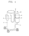
- Fig. 1 is a perspective view showing an outer appearance of a scroll compressor having an oil separating unit disposed outside a casing according to the present invention
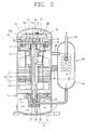
- Fig. 2 is a longitudinal sectional view showing an inside of the scroll compressor of Fig. 1 ;
- Fig. 3 is a perspective view showing an oil supplying pump and an oil recollecting pump of Fig. 1 ;
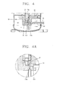
- Fig. 4 is a longitudinal sectional view showing another exemplary embodiment of the oil recollecting unit according to the present invention, and Fig. 4A is a detailed view of the inlets of the oil recollecting unit as designated by call-out A of Fig. 4 ;
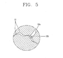
- Fig. 5 is a schematic view showing an inlet of the oil recollecting pump of Fig. 4 ;
- Fig. 6 is a longitudinal sectional view showing another exemplary embodiment of a scroll compressor having an oil separating unit disposed outside a casing according to the present invention
- Fig. 7 is a longitudinal sectional view showing an exemplary embodiment of a scroll compressor having an oil separating unit disposed inside a casing according to the present invention
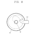
- Fig. 8 is a horizontal sectional view showing a fluid flowing state in an oil separating cap of Fig. 7 ;
- Fig. 9 is a longitudinal section view showing another exemplary embodiment of a scroll compressor having an oil separating unit disposed outside a casing according to the present invention.
- Fig. 1 is a perspective view showing an outer appearance of a scroll compressor according to a first exemplary embodiment of the present invention where an oil separating unit is disposed outside a casing
- Fig. 2 is a longitudinal sectional view showing an inside of the scroll compressor of Fig. 1
- Fig. 3 is a perspective view showing an oil supplying pump and an oil recollecting pump of Fig. 1
- the scroll compressor according to the present invention may include a compressor casing (hereinafter, referred to as 'casing') 10 having a hermetic inner space, a motor 20 located in the inner space of the casing 10, and a compressing unit 30 driven by the motor 20.
- the compressing unit 30 includes a fixed scroll 31 and an orbiting scroll 32 driven by the motor 20 to compress a refrigerant.
- the inner space of the casing 10 is configured to hold a refrigerant at a suitable discharge pressure.
- a suction pipe SP is formed through one side of the casing 10 to be in communication with a suction chamber formed by the fixed scroll 31 and the orbiting scroll 32.
- a discharge pipe DP is connected to another side of the casing 10 to guide a refrigerant discharged out of the inner space of the casing 10 to a refrigeration cycle.
- the motor 20 may be a constant speed motor rotating at a uniform speed, or an inverter motor rotating at variable speed depending on the needs of a refrigerating device to which the compressor is applied.
- a crankshaft 23 of the motor 20 is supported by a main frame 11 and a sub-frame 12 fixedly installed at both upper and lower ends of the casing 10.
- An oil passage 23a is formed through the crankshaft 23 in an axial direction.
- An oil supplying pump 25 for pumping oil contained in the casing 10 is disposed below the oil passage 23a, in particular, below the crankshaft 23.
- a displacement pump may be used as the oil supplying pump 25 as shown in Fig. 2 .
- An example of such a displacement pump includes a trochoid gear pump which forms a variable capacity between an inner gear and an outer gear so as to pump oil.
- An oil suction pipe 26 is connected to an inlet of the oil supplying pump 25 to suck oil located in a bottom of the casing 10.
- the oil suction pipe 26 has an inlet with a suitable length so as to extend into the oil contained at the bottom of the casing 10.
- the compressing unit 30, as shown in Fig. 2 includes the fixed scroll 31 coupled to the main frame 11, the orbiting scroll 32 engaged with the fixed scroll 31 to provide a pair of compression chambers P which continuously move, an Oldham ring 33 disposed between the orbiting scroll 32 and the main frame 11 to induce the orbiting motion of the orbiting scroll 32, and a check valve 34 disposed to switch a discharge opening 31c of the fixed scroll 31 so as to block a backflow of discharge gas discharged through the discharge opening 31c.
- a fixed wrap 31a and an orbiting wrap 32a are spirally provided at the fixed scroll 31 and the orbiting scroll 32, respectively.
- the fixed wrap 31a and the orbiting wrap 32a are engaged with each other to form the compression chambers P.
- the suction pipe SP is directly connected to a suction opening 31b of the fixed scroll 31 for guiding a refrigerant from the refrigeration cycle into the compressor.
- the compressed refrigerant is continuously discharged to an upper space S1 of the casing 10 through the discharge opening 31c of the fixed scroll 31 and then moved down to a lower space S2 of the casing 10, thereby being discharged into a refrigeration cycle system through the refrigerant discharge pipe DP.
- the compressed refrigerant may be moved from upper space S1 to lower space S2 using various approaches, such as, for example providing a passage (not shown) through the fixed scroll 31 and/or main frame 11.
- the oil supplying pump 25 disposed below the crankshaft 23 pumps oil contained in the casing 10 using a variable capacity formed between the inner gear and outer gear of the oil supplying pump 25. Oil is sucked toward an upper end through the oil passage 23a of the crankshaft 23 and the oil is partially supplied to respective bearing surfaces of the sub-frame 12 and the main frame 11, and partially supplied to the compression chambers P through a bearing surface between the main frame 11 and the orbiting scroll 12 at the upper end of the crankshaft 23 so as to seal or smooth the compression chambers P.
- the oil recollecting pump 52 pumps and recollects oil separated from a refrigerant discharged out of the compressing unit. A detailed description thereof will now be given.
- an oil separating unit 40 for separating oil from a refrigerant discharged into the refrigeration cycle through the discharge pipe DP is located at an outlet portion of the discharge pipe DP outside the casing 10.
- an oil recollecting unit 50 is connected to the oil separating unit 40.
- the oil recollecting unit 50 is configured to pump oil separated from a refrigerant by the oil separating unit 40 and to either recollect the separated oil in the inner space of the casing 10 (See Fig. 6 ) or to recollect such oil directly into the oil passage 23a of the crankshaft 23.
- the oil separating unit 40 may include an oil separator 41 disposed in parallel with one side of the casing 10, and an oil separating member (not shown) disposed at the oil separator 41 to separate oil from a refrigerant discharged from the compressing unit 30.
- the oil separator 41 may be supported by being connected to the discharge pipe DP at its middle portion or supported by a supporting member 42 (e.g., a clamp) separately disposed between the casing 10 and the oil separator 41.
- a refrigerant pipe RP is connected to an upper end of the oil separator 41 to allow the separated refrigerant to flow toward a condenser of the refrigeration cycle.
- An oil recollecting pipe 51 is connected to a lower end of the oil separator 41 such that oil separated by the oil separator 41 can be recollected into the casing 10 of the compressor or directly into the compressing unit 30 via the oil passage 23a.
- the oil separating unit 40 may use various methods for separating oil.
- a mesh screen may be installed inside the oil separator 41 to thereby separate oil from a refrigerant, or the discharge pipe DP may be connected to the oil separator 41 at an incline such that a refrigerant rotates in a form of cyclone to thereby separate relatively heavy oil from the refrigerant.
- the oil recollecting unit 50 may include the oil recollecting pipe 51 connected to the oil separating unit 40 to guide oil, and an oil recollecting pump 52 installed at the oil recollecting pipe 51 to pump oil from the oil separator 41.
- One end of the oil recollecting pipe 51 is connected to the lower end of the oil separator 41, and the other end thereof penetrates through the casing 10 to be connected to an inlet of the oil recollecting pump 52.
- the oil recollecting pipe 51 may be a metallic pipe having a suitable strength so as to stably support the oil separator 41.
- the oil recollecting pipe 51 may be curved through an angle so that the oil separator 41 is oriented parallel with the casing 10, thus to reduce a vibration of the compressor.
- the oil recollecting pump 52 may be installed above or below the oil supplying pump 25 to be driven by a driving force from the motor 20.
- the oil recollecting pump 52 may be a trochoid gear pump in which an inner gear is coupled to the crankshaft 23 of the motor 20 and the inner gear is engaged with an outer gear to provide a variable capacity.
- An outlet of the oil recollecting pump 52 is in communication with an outlet of the oil supplying pump 25 such that oil recollected through the oil recollecting pump 52 can be introduced into the oil passage 23a of the crankshaft 23 together with oil sucked through the oil supplying pump 25.
- the outlet of the oil recollecting pump 52 and the outlet of the oil supplying pump 25 may be independently formed to allow oils from each of them to be independently introduced into the oil passage 23a of the crankshaft 23.
- the oil separator 41 separates oil from a refrigerant discharged out of the inner space of the casing 10. Such separated oil is recollected into the inner space of the casing 10 via the oil recollecting pump 52, or may be directly be supplied into the oil passage 23a of the crankshaft 23.
- oil introduced into the compression chamber P is discharged together with a refrigerant to be introduced into the oil separator 41 via the discharge pipe DP.
- Such oil and refrigerant are separated from each other in the oil separator 41.
- the separated refrigerant then flows up to a condenser of the refrigeration cycle via the refrigerant pipe RP whereas the separated oil is collected at the bottom of the oil separator 41.
- the inner gear of the oil recollecting pump 52 rotates so as to configure a variable capacity between the inner gear and the outer gear, thereby generating a pumping force.
- the oil separated by the oil separator 41 is pumped by such pumping force.
- the oil pumped by the oil recollecting pump 52 is recollected into the inner space of the casing 10 through the oil recollecting pipe 51 and the oil recollecting pump 52.
- Such recollected oil is accordingly re-supplied to each bearing surface and the compression chamber P by the oil supplying pump 52 via the oil passage 23a of the crankshaft 23. This process may be continuously repeated as the crankshaft 23 rotates.
- An oil supplying hole 14 for injecting oil into the inner space of the casing 10 may be formed at a lower portion of the casing 10.
- the oil supplying hole 14 may be used as an oil equalizing hole to place the plurality of compressors in communication with each other in order to match liquid-level heights of each of the compressors.
- the first exemplary embodiment of the compressor includes an oil supplying pump
- a second exemplary embodiment is provided where a single oil recollecting pump is used to perform the function of the oil supplying pump.
- the second exemplary embodiment of the scroll compressor may be implemented as follows. As shown in Figs. 4 and 5 , the oil recollecting pump 52, which may be a trochoid gear pump, is installed below the crankshaft 23, and a first inlet 52a of the oil recollecting pump 52 is connected to an outlet of the oil recollecting pipe 51 while a second inlet 52b of the oil recollecting pump 52 is sunk in oil collected at the bottom of the casing 10.
- the scroll compressor in accordance with this exemplary embodiment is similar to that of the aforesaid embodiment in the basic configuration and operations, and accordingly a detailed description thereof will not be repeated.
- the inlet of the oil recollecting pump 52 is divided into the first inlet 52a and the second inlet 52b. Accordingly, oil separated by the oil separator 41 is sucked through the first inlet 52a while oil collected at the bottom of the casing 10 is sucked through the second inlet 52b.
- Such oils sucked through the first and second inlets 52a and 52b are all collected into the oil passage 23a of the crankshaft 23 to be supplied to each bearing surface or the compression chamber P.
- a scroll compressor according to the present invention will be described hereafter. While the aforementioned exemplary embodiments are configured such that the oil recollecting pump is installed inside the casing or coupled to the motor to use the driving force of the motor, a third exemplary embodiment of the scroll compressor, as shown in Fig. 6 , is configured such that an oil recollecting pump 152 of an oil recollecting unit 150 is installed outside the casing 10, and is driven by a separate driving force, other than the driving force of the motor.
- the oil recollecting pump 152 is installed at an intermediate portion of the oil recollecting pipe 151 at the outside of the casing 10, and an inverter motor having a rotation velocity, which can be changed (increase or decrease), in proportion to the rotation velocity of the motor 20 is provided.
- the oil recollecting pipe 151 may have an outlet which is directly connectable to the oil passage 23a of the crankshaft 23, however, in some cases, it may be connected to the inner space of the casing 10.
- an oil separating unit 240 may include an oil separating cap 241 fixedly installed in the inner space of the casing 10 and an oil separating pipe 242 formed through one side wall surface of the oil separating cap 241 such that oil and refrigerant inside the casing 10 can be separated from each other while being introduced into the oil separating cap 241.
- the oil separating cap 241 may have a gap spaced apart from the inner surface of the casing 10.
- a guide cover 15 having a certain inner space to accommodate a discharge side of the compressing unit 30 is installed between the compressing unit 30 and the oil separating unit 240.
- An inlet side fluid passage (not shown) is formed at a portion of the compressing unit 30 which is accommodated in the guide cover 15, whereas an outlet side fluid passage (not shown) is formed at a portion of the compressing unit 30 which is not accommodated in the guide cover 15. Accordingly, refrigerant and oil discharged from the compression chamber P is allowed to flow toward a lower space S2 of the casing 10, namely, toward the motor 20 and then to flow toward an upper space S1 of the casing 10, in particular, toward the oil separating cap 241.
- the discharge pipe DP for guiding the refrigerant separated by the oil separating cap 241 to the refrigeration cycle is connected to another side wall surface of the oil separating cap 241.
- the discharge pipe DP is then connected to the refrigeration cycle through the casing 10.
- An oil recollecting pipe 251 for guiding oil separated by the oil separating cap 241 to the bottom of the casing 10 is connected to a lower end of the oil separating cap 241.
- An oil recollecting pump 252 for pumping oil separated by the oil separating cap 241 is located at an outlet of the oil recollecting pipe 251.
- the oil separating pipe 242 includes an inlet in communication with the upper space S1 of the casing 10 and an outlet in communication with the inner space of the oil separating cap 241.
- the oil separating pipe 242 may be formed to be curved or bent, as shown in Fig. 8 , such that refrigerant and oil guided into the oil separating cap 241 are separated from each other while spirally orbiting together.
- the inlet of the oil recollecting pipe 251, as shown in Fig. 7 , is in communication with the lower end of the oil separating cap 241 and then penetrates through the compressing unit 30, thereby being in communication with the inlet of an oil supplying pump 252.
- an oil passage (not shown) for connecting the oil separating cap 241 to the oil recollecting pipe 251 is formed through the fixed scroll 31 and the main frame 11.
- the oil recollecting pump 252 may be a trochoid gear pump having inner gear and outer gear as described above.
- the inner gear may be configured as same as in the aforementioned embodiments, such as being coupled to the crankshaft 23 of the motor 20.
- the operation of this exemplary embodiment of the present invention the process in which oil is separated from the refrigerant to be recollected is the same or similar to those described above, so a detailed explanation thereof will not be repeated.
- the oil separating unit 240 is installed inside the casing 10, the flow direction of the refrigerant and oil is different from that in the previous embodiments. That is, refrigerant and oil, after being discharged from the compression chamber P into the inner space of the guide cover 15, flow to the lower space S2 via the inlet side fluid passage. Thereafter, the refrigerant and oil flow to the upper space S 1 through the outlet side fluid passage.
- the refrigerant and oil are then introduced into the oil separating cap 241 through the oil separating pipe 242 to orbit inside the oil separating cap 241. Accordingly, the refrigerant and the oil are separated from each other. Afterwards, the separated refrigerant then flows to the refrigeration cycle through the discharge pipe DP whereas the separated oil is recollected to the oil passage 23a of the crankshaft 23 through the oil recollecting pipe 251 by a pumping force of the oil recollecting pump 252. This process may be continuously repeated as the crankshaft 23 rotates.
- the scroll compressor may be configured to draw the oil recollecting pipe 251 out of the casing 10 to be then connected to the inside of the casing 10.
- a radiating member (not shown) or a capillary tube (not shown) for lowering an oil temperature may be provided at the intermediate portion of the oil recollecting pipe 251.
- An oil recollecting pump 252 may include an inverter motor as described above with reference to Fig. 6 , and may be located at the intermediate portion of the oil recollecting pipe 251.
- oil separated by the oil separator is recollected by the oil recollecting pump.
- the recollected oil is mixed with a refrigerant again, whereby it is allowed to prevent a backflow of such oil into the compressor.
- the simplification of the oil recollecting unit allows the decrease of manufacturing cost.
- the configuration of the compressor can be further simplified.
Landscapes
- Engineering & Computer Science (AREA)
- Mechanical Engineering (AREA)
- General Engineering & Computer Science (AREA)
- Physics & Mathematics (AREA)
- Thermal Sciences (AREA)
- Chemical & Material Sciences (AREA)
- Analytical Chemistry (AREA)
- Power Engineering (AREA)
- Rotary Pumps (AREA)
- Applications Or Details Of Rotary Compressors (AREA)
- Compressor (AREA)
Claims (5)
- Verdichter mit:einem Verdichterhauptkörper mit einem Gehäuse (10), das einen Innenraum definiert, einer feststehenden Schnecke, die fest am Gehäuse angebracht ist, und einer umlaufenden Schnecke, die mit der feststehenden Schnecke in Eingriff ist und zusammen mit einem Motor (20) umläuft, wobei die feststehende und die umlaufende Schnecke ein Paar Verdichtungskammern (P) definieren;einem mit einem Einlass der Verdichtungskammern verbundenen Ansaugrohr;einem mit dem Gehäuse verbundenen Auslassrohr;wobei der Motor (20) im Innenraum des Gehäuses im Verdichter angebracht ist;einer Öltrennvorrichtung, die dazu ausgebildet ist, Öl vom von den Verdichtungskammern freigesetztem Kältemittel zu trennen; undeiner Ölsammelvorrichtung (150), die dazu ausgebildet ist, das durch die Öltrennvorrichtung getrennte ÖI zu pumpen und das getrennte Öl im Gehäuse zu sammeln;dadurch gekennzeichnet, dassdas Ansaugrohr über eine Seite des Gehäuses direkt mit einer Ansaugöffnung der feststehenden Schnecke verbunden ist unddie Ölsammelvorrichtung (150) aufweist:ein Ölsammelrohr (151), dessen eines Ende mit dem Innenraum des Gehäuses verbunden ist und dessen anderes Ende mit dem Auslass der Öltrennvorrichtung verbunden ist, undeine Ölsammelpumpe (152), die in einem mittleren Bereich des Ölsammelrohrs zum Pumpen des von der Öltrennvorrichtung getrennten Öls angeordnet ist.
- Verdichter nach Anspruch 1, ferner mit einer Ölzufuhrpumpe, wobei der Motor eine Kurbelwelle aufweist und die Ölzufuhrpumpe mit der Kurbelwelle des Motors verbunden ist, wodurch im Gehäuse befindliches Öl gepumpt wird.
- Verdichter nach Anspruch 2, wobei die Ölzufuhrpumpe einen Einlass und einen Auslass aufweist, die Ölsammelpumpe einen Einlass und einen Auslass aufweist und der Einlass und der Auslass der Ölzufuhrpumpe unabhängig vom Einlass und vom Auslass der Ölsammelpumpe angeordnet sind.
- Verdichter nach Anspruch 1, wobei die Ölsammelpumpe einen Umrichtermotor aufweist, so dass eine Pumpleistung im Verhältnis zu einer Motordrehgeschwindigkeit variabel ist.
- Verdichter nach einem der Ansprüche 1 bis 4, wobei sich die Öltrennvorrichtung außerhalb des Gehäuses des Verdichterhauptkörpers befindet, wobei ein Einlass der Öltrennvorrichtung über das Auslassrohr mit dem Verdichterhauptkörper und ein Auslass der Öltrennvorrichtung über das Ölsammelrohr mit dem Innenraum des Gehäuses verbunden sind.
Applications Claiming Priority (3)
| Application Number | Priority Date | Filing Date | Title |
|---|---|---|---|
| KR1020070076579 | 2007-07-30 | ||
| KR20070139286 | 2007-12-27 | ||
| KR1020080070336A KR101275185B1 (ko) | 2008-07-18 | 2008-07-18 | 압축기 |
Publications (3)
| Publication Number | Publication Date |
|---|---|
| EP2020577A2 EP2020577A2 (de) | 2009-02-04 |
| EP2020577A3 EP2020577A3 (de) | 2011-03-30 |
| EP2020577B1 true EP2020577B1 (de) | 2014-09-24 |
Family
ID=40029310
Family Applications (1)
| Application Number | Title | Priority Date | Filing Date |
|---|---|---|---|
| EP08161400.0A Not-in-force EP2020577B1 (de) | 2007-07-30 | 2008-07-30 | Verdichter |
Country Status (4)
| Country | Link |
|---|---|
| US (1) | US20090031753A1 (de) |
| EP (1) | EP2020577B1 (de) |
| JP (1) | JP2009030611A (de) |
| ES (1) | ES2507559T3 (de) |
Families Citing this family (7)
| Publication number | Priority date | Publication date | Assignee | Title |
|---|---|---|---|---|
| KR101513632B1 (ko) * | 2008-11-14 | 2015-04-20 | 엘지전자 주식회사 | 밀폐형 압축기 및 이를 적용한 냉동기기 |
| JP2010243108A (ja) * | 2009-04-08 | 2010-10-28 | Sanden Corp | 油分離器 |
| JP6209730B2 (ja) * | 2013-03-27 | 2017-10-11 | パナソニックIpマネジメント株式会社 | 密閉型圧縮機 |
| WO2014196168A1 (ja) * | 2013-06-06 | 2014-12-11 | パナソニックIpマネジメント株式会社 | 油分離器および油分離器を製造する製造方法 |
| GB201321629D0 (en) | 2013-12-06 | 2014-01-22 | J & E Hall Ltd | External separator |
| JP2021014812A (ja) * | 2019-07-11 | 2021-02-12 | ダイキン工業株式会社 | 圧縮機及び冷凍装置 |
| JP6985625B2 (ja) * | 2020-03-31 | 2021-12-22 | ダイキン工業株式会社 | 油分離器 |
Family Cites Families (15)
| Publication number | Priority date | Publication date | Assignee | Title |
|---|---|---|---|---|
| JPS4915561B1 (de) * | 1970-06-29 | 1974-04-16 | ||
| JPH02230993A (ja) * | 1989-03-01 | 1990-09-13 | Daikin Ind Ltd | スクロール型流体装置 |
| JP2666612B2 (ja) * | 1991-07-18 | 1997-10-22 | 株式会社日立製作所 | 密閉形スクロール圧縮機 |
| JPH05223074A (ja) * | 1992-02-07 | 1993-08-31 | Zexel Corp | スクロール型コンプレッサのオイル循環機構 |
| JP3395495B2 (ja) * | 1995-12-26 | 2003-04-14 | ダイキン工業株式会社 | 密閉形圧縮機 |
| TW362142B (en) * | 1996-05-23 | 1999-06-21 | Sanyo Electric Co | Horizontal compressor |
| JP3499110B2 (ja) * | 1997-08-11 | 2004-02-23 | 株式会社神戸製鋼所 | 油冷式スクリュ圧縮機 |
| JPH11294332A (ja) * | 1998-04-08 | 1999-10-26 | Matsushita Electric Ind Co Ltd | 冷凍サイクルの圧縮機 |
| JP2003139059A (ja) * | 2001-10-31 | 2003-05-14 | Daikin Ind Ltd | 流体機械 |
| JP2004353565A (ja) * | 2003-05-29 | 2004-12-16 | Daikin Ind Ltd | スクロール型圧縮機 |
| JP2005240637A (ja) * | 2004-02-25 | 2005-09-08 | Mitsubishi Heavy Ind Ltd | ガス圧縮ユニット |
| KR100724387B1 (ko) * | 2005-09-28 | 2007-06-04 | 엘지전자 주식회사 | 밀폐형 압축기의 오일 펌핑 장치 |
| KR100864754B1 (ko) * | 2005-11-28 | 2008-10-22 | 엘지전자 주식회사 | 스크롤 압축기의 오일 공급 구조 |
| KR100688656B1 (ko) * | 2005-11-28 | 2007-03-02 | 엘지전자 주식회사 | 스크롤 압축기의 오일 공급 구조 |
| KR100751152B1 (ko) * | 2005-11-30 | 2007-08-22 | 엘지전자 주식회사 | 스크롤 압축기의 오일 공급 구조 |
-
2008
- 2008-07-29 JP JP2008195260A patent/JP2009030611A/ja active Pending
- 2008-07-29 US US12/181,987 patent/US20090031753A1/en not_active Abandoned
- 2008-07-30 EP EP08161400.0A patent/EP2020577B1/de not_active Not-in-force
- 2008-07-30 ES ES08161400.0T patent/ES2507559T3/es active Active
Also Published As
| Publication number | Publication date |
|---|---|
| EP2020577A3 (de) | 2011-03-30 |
| JP2009030611A (ja) | 2009-02-12 |
| ES2507559T3 (es) | 2014-10-15 |
| EP2020577A2 (de) | 2009-02-04 |
| US20090031753A1 (en) | 2009-02-05 |
Similar Documents
| Publication | Publication Date | Title |
|---|---|---|
| EP2020578B1 (de) | Hermetischer Verdichter und Kältekreislaufvorrichtung damit | |
| US8992191B2 (en) | Scroll compressor with differential pressure hole | |
| US8419394B2 (en) | Hermetic compressor including a backflow preventing portion and refrigeration cycle device having the same | |
| KR102243681B1 (ko) | 스크롤 압축기 | |
| US7473083B2 (en) | Oil separating device for compressor | |
| EP3194783B1 (de) | Scrollverdichter und klimaanlage damit | |
| EP2182307B1 (de) | Hermetischer Verdichter | |
| EP2020577B1 (de) | Verdichter | |
| EP2115302B1 (de) | Verdichter und ölsperrvorrichtung dafür | |
| EP2177765A2 (de) | Spiralverdichter und Kühlmaschine mit diesem Verdichter | |
| EP2243958A2 (de) | Verdichter und Kühlvorrichtung damit | |
| EP2177766A2 (de) | Spiralverdichter und Kühlmaschine mit diesem Verdichter | |
| US20190309753A1 (en) | Scroll compressor | |
| US8342827B2 (en) | Hermetic compressor and refrigeration cycle device having the same | |
| KR101964962B1 (ko) | 냉매 역류 방지 구조가 구비된 압축기 | |
| KR101451663B1 (ko) | 밀폐형 압축기 및 이를 적용한 냉동사이클 장치 | |
| US20070122303A1 (en) | Oil pump of scroll compressor | |
| KR101275185B1 (ko) | 압축기 | |
| KR20100046596A (ko) | 밀폐형 압축기 및 이를 적용한 냉동기기 | |
| EP4191064B1 (de) | Spiralverdichter | |
| KR101474462B1 (ko) | 밀폐형 압축기 |
Legal Events
| Date | Code | Title | Description |
|---|---|---|---|
| PUAI | Public reference made under article 153(3) epc to a published international application that has entered the european phase |
Free format text: ORIGINAL CODE: 0009012 |
|
| AK | Designated contracting states |
Kind code of ref document: A2 Designated state(s): AT BE BG CH CY CZ DE DK EE ES FI FR GB GR HR HU IE IS IT LI LT LU LV MC MT NL NO PL PT RO SE SI SK TR |
|
| AX | Request for extension of the european patent |
Extension state: AL BA MK RS |
|
| PUAL | Search report despatched |
Free format text: ORIGINAL CODE: 0009013 |
|
| AK | Designated contracting states |
Kind code of ref document: A3 Designated state(s): AT BE BG CH CY CZ DE DK EE ES FI FR GB GR HR HU IE IS IT LI LT LU LV MC MT NL NO PL PT RO SE SI SK TR |
|
| AX | Request for extension of the european patent |
Extension state: AL BA MK RS |
|
| 17P | Request for examination filed |
Effective date: 20110930 |
|
| AKX | Designation fees paid |
Designated state(s): AT BE BG CH CY CZ DE DK EE ES FI FR GB GR HR HU IE IS IT LI LT LU LV MC MT NL NO PL PT RO SE SI SK TR |
|
| 17Q | First examination report despatched |
Effective date: 20130424 |
|
| GRAJ | Information related to disapproval of communication of intention to grant by the applicant or resumption of examination proceedings by the epo deleted |
Free format text: ORIGINAL CODE: EPIDOSDIGR1 |
|
| GRAP | Despatch of communication of intention to grant a patent |
Free format text: ORIGINAL CODE: EPIDOSNIGR1 |
|
| GRAP | Despatch of communication of intention to grant a patent |
Free format text: ORIGINAL CODE: EPIDOSNIGR1 |
|
| INTG | Intention to grant announced |
Effective date: 20140402 |
|
| INTC | Intention to grant announced (deleted) | ||
| INTG | Intention to grant announced |
Effective date: 20140415 |
|
| GRAS | Grant fee paid |
Free format text: ORIGINAL CODE: EPIDOSNIGR3 |
|
| GRAA | (expected) grant |
Free format text: ORIGINAL CODE: 0009210 |
|
| AK | Designated contracting states |
Kind code of ref document: B1 Designated state(s): AT BE BG CH CY CZ DE DK EE ES FI FR GB GR HR HU IE IS IT LI LT LU LV MC MT NL NO PL PT RO SE SI SK TR |
|
| REG | Reference to a national code |
Ref country code: GB Ref legal event code: FG4D |
|
| REG | Reference to a national code |
Ref country code: CH Ref legal event code: EP |
|
| REG | Reference to a national code |
Ref country code: ES Ref legal event code: FG2A Ref document number: 2507559 Country of ref document: ES Kind code of ref document: T3 Effective date: 20141015 Ref country code: AT Ref legal event code: REF Ref document number: 688812 Country of ref document: AT Kind code of ref document: T Effective date: 20141015 |
|
| REG | Reference to a national code |
Ref country code: IE Ref legal event code: FG4D |
|
| REG | Reference to a national code |
Ref country code: DE Ref legal event code: R096 Ref document number: 602008034523 Country of ref document: DE Effective date: 20141106 |
|
| PG25 | Lapsed in a contracting state [announced via postgrant information from national office to epo] |
Ref country code: FI Free format text: LAPSE BECAUSE OF FAILURE TO SUBMIT A TRANSLATION OF THE DESCRIPTION OR TO PAY THE FEE WITHIN THE PRESCRIBED TIME-LIMIT Effective date: 20140924 Ref country code: GR Free format text: LAPSE BECAUSE OF FAILURE TO SUBMIT A TRANSLATION OF THE DESCRIPTION OR TO PAY THE FEE WITHIN THE PRESCRIBED TIME-LIMIT Effective date: 20141225 Ref country code: NO Free format text: LAPSE BECAUSE OF FAILURE TO SUBMIT A TRANSLATION OF THE DESCRIPTION OR TO PAY THE FEE WITHIN THE PRESCRIBED TIME-LIMIT Effective date: 20141224 Ref country code: SE Free format text: LAPSE BECAUSE OF FAILURE TO SUBMIT A TRANSLATION OF THE DESCRIPTION OR TO PAY THE FEE WITHIN THE PRESCRIBED TIME-LIMIT Effective date: 20140924 Ref country code: LT Free format text: LAPSE BECAUSE OF FAILURE TO SUBMIT A TRANSLATION OF THE DESCRIPTION OR TO PAY THE FEE WITHIN THE PRESCRIBED TIME-LIMIT Effective date: 20140924 |
|
| REG | Reference to a national code |
Ref country code: LT Ref legal event code: MG4D Ref country code: NL Ref legal event code: VDEP Effective date: 20140924 |
|
| PG25 | Lapsed in a contracting state [announced via postgrant information from national office to epo] |
Ref country code: HR Free format text: LAPSE BECAUSE OF FAILURE TO SUBMIT A TRANSLATION OF THE DESCRIPTION OR TO PAY THE FEE WITHIN THE PRESCRIBED TIME-LIMIT Effective date: 20140924 Ref country code: LV Free format text: LAPSE BECAUSE OF FAILURE TO SUBMIT A TRANSLATION OF THE DESCRIPTION OR TO PAY THE FEE WITHIN THE PRESCRIBED TIME-LIMIT Effective date: 20140924 Ref country code: CY Free format text: LAPSE BECAUSE OF FAILURE TO SUBMIT A TRANSLATION OF THE DESCRIPTION OR TO PAY THE FEE WITHIN THE PRESCRIBED TIME-LIMIT Effective date: 20140924 |
|
| REG | Reference to a national code |
Ref country code: AT Ref legal event code: MK05 Ref document number: 688812 Country of ref document: AT Kind code of ref document: T Effective date: 20140924 |
|
| PG25 | Lapsed in a contracting state [announced via postgrant information from national office to epo] |
Ref country code: NL Free format text: LAPSE BECAUSE OF FAILURE TO SUBMIT A TRANSLATION OF THE DESCRIPTION OR TO PAY THE FEE WITHIN THE PRESCRIBED TIME-LIMIT Effective date: 20140924 |
|
| PG25 | Lapsed in a contracting state [announced via postgrant information from national office to epo] |
Ref country code: CZ Free format text: LAPSE BECAUSE OF FAILURE TO SUBMIT A TRANSLATION OF THE DESCRIPTION OR TO PAY THE FEE WITHIN THE PRESCRIBED TIME-LIMIT Effective date: 20140924 Ref country code: EE Free format text: LAPSE BECAUSE OF FAILURE TO SUBMIT A TRANSLATION OF THE DESCRIPTION OR TO PAY THE FEE WITHIN THE PRESCRIBED TIME-LIMIT Effective date: 20140924 Ref country code: SK Free format text: LAPSE BECAUSE OF FAILURE TO SUBMIT A TRANSLATION OF THE DESCRIPTION OR TO PAY THE FEE WITHIN THE PRESCRIBED TIME-LIMIT Effective date: 20140924 Ref country code: RO Free format text: LAPSE BECAUSE OF FAILURE TO SUBMIT A TRANSLATION OF THE DESCRIPTION OR TO PAY THE FEE WITHIN THE PRESCRIBED TIME-LIMIT Effective date: 20140924 Ref country code: PT Free format text: LAPSE BECAUSE OF FAILURE TO SUBMIT A TRANSLATION OF THE DESCRIPTION OR TO PAY THE FEE WITHIN THE PRESCRIBED TIME-LIMIT Effective date: 20150126 Ref country code: IS Free format text: LAPSE BECAUSE OF FAILURE TO SUBMIT A TRANSLATION OF THE DESCRIPTION OR TO PAY THE FEE WITHIN THE PRESCRIBED TIME-LIMIT Effective date: 20150124 |
|
| PG25 | Lapsed in a contracting state [announced via postgrant information from national office to epo] |
Ref country code: AT Free format text: LAPSE BECAUSE OF FAILURE TO SUBMIT A TRANSLATION OF THE DESCRIPTION OR TO PAY THE FEE WITHIN THE PRESCRIBED TIME-LIMIT Effective date: 20140924 Ref country code: PL Free format text: LAPSE BECAUSE OF FAILURE TO SUBMIT A TRANSLATION OF THE DESCRIPTION OR TO PAY THE FEE WITHIN THE PRESCRIBED TIME-LIMIT Effective date: 20140924 |
|
| REG | Reference to a national code |
Ref country code: FR Ref legal event code: PLFP Year of fee payment: 8 |
|
| REG | Reference to a national code |
Ref country code: DE Ref legal event code: R097 Ref document number: 602008034523 Country of ref document: DE |
|
| PG25 | Lapsed in a contracting state [announced via postgrant information from national office to epo] |
Ref country code: DK Free format text: LAPSE BECAUSE OF FAILURE TO SUBMIT A TRANSLATION OF THE DESCRIPTION OR TO PAY THE FEE WITHIN THE PRESCRIBED TIME-LIMIT Effective date: 20140924 |
|
| PLBE | No opposition filed within time limit |
Free format text: ORIGINAL CODE: 0009261 |
|
| STAA | Information on the status of an ep patent application or granted ep patent |
Free format text: STATUS: NO OPPOSITION FILED WITHIN TIME LIMIT |
|
| 26N | No opposition filed |
Effective date: 20150625 |
|
| PG25 | Lapsed in a contracting state [announced via postgrant information from national office to epo] |
Ref country code: MC Free format text: LAPSE BECAUSE OF FAILURE TO SUBMIT A TRANSLATION OF THE DESCRIPTION OR TO PAY THE FEE WITHIN THE PRESCRIBED TIME-LIMIT Effective date: 20140924 Ref country code: SI Free format text: LAPSE BECAUSE OF FAILURE TO SUBMIT A TRANSLATION OF THE DESCRIPTION OR TO PAY THE FEE WITHIN THE PRESCRIBED TIME-LIMIT Effective date: 20140924 |
|
| REG | Reference to a national code |
Ref country code: CH Ref legal event code: PL |
|
| GBPC | Gb: european patent ceased through non-payment of renewal fee |
Effective date: 20150730 |
|
| PG25 | Lapsed in a contracting state [announced via postgrant information from national office to epo] |
Ref country code: LU Free format text: LAPSE BECAUSE OF FAILURE TO SUBMIT A TRANSLATION OF THE DESCRIPTION OR TO PAY THE FEE WITHIN THE PRESCRIBED TIME-LIMIT Effective date: 20150730 |
|
| REG | Reference to a national code |
Ref country code: IE Ref legal event code: MM4A |
|
| PG25 | Lapsed in a contracting state [announced via postgrant information from national office to epo] |
Ref country code: LI Free format text: LAPSE BECAUSE OF NON-PAYMENT OF DUE FEES Effective date: 20150731 Ref country code: GB Free format text: LAPSE BECAUSE OF NON-PAYMENT OF DUE FEES Effective date: 20150730 Ref country code: CH Free format text: LAPSE BECAUSE OF NON-PAYMENT OF DUE FEES Effective date: 20150731 |
|
| REG | Reference to a national code |
Ref country code: FR Ref legal event code: PLFP Year of fee payment: 9 |
|
| PG25 | Lapsed in a contracting state [announced via postgrant information from national office to epo] |
Ref country code: IE Free format text: LAPSE BECAUSE OF NON-PAYMENT OF DUE FEES Effective date: 20150730 |
|
| PG25 | Lapsed in a contracting state [announced via postgrant information from national office to epo] |
Ref country code: MT Free format text: LAPSE BECAUSE OF FAILURE TO SUBMIT A TRANSLATION OF THE DESCRIPTION OR TO PAY THE FEE WITHIN THE PRESCRIBED TIME-LIMIT Effective date: 20140924 |
|
| PG25 | Lapsed in a contracting state [announced via postgrant information from national office to epo] |
Ref country code: HU Free format text: LAPSE BECAUSE OF FAILURE TO SUBMIT A TRANSLATION OF THE DESCRIPTION OR TO PAY THE FEE WITHIN THE PRESCRIBED TIME-LIMIT; INVALID AB INITIO Effective date: 20080730 Ref country code: BG Free format text: LAPSE BECAUSE OF FAILURE TO SUBMIT A TRANSLATION OF THE DESCRIPTION OR TO PAY THE FEE WITHIN THE PRESCRIBED TIME-LIMIT Effective date: 20140924 |
|
| REG | Reference to a national code |
Ref country code: FR Ref legal event code: PLFP Year of fee payment: 10 |
|
| PG25 | Lapsed in a contracting state [announced via postgrant information from national office to epo] |
Ref country code: TR Free format text: LAPSE BECAUSE OF FAILURE TO SUBMIT A TRANSLATION OF THE DESCRIPTION OR TO PAY THE FEE WITHIN THE PRESCRIBED TIME-LIMIT Effective date: 20140924 |
|
| PG25 | Lapsed in a contracting state [announced via postgrant information from national office to epo] |
Ref country code: BE Free format text: LAPSE BECAUSE OF FAILURE TO SUBMIT A TRANSLATION OF THE DESCRIPTION OR TO PAY THE FEE WITHIN THE PRESCRIBED TIME-LIMIT Effective date: 20140924 |
|
| REG | Reference to a national code |
Ref country code: FR Ref legal event code: PLFP Year of fee payment: 11 |
|
| PGFP | Annual fee paid to national office [announced via postgrant information from national office to epo] |
Ref country code: ES Payment date: 20180808 Year of fee payment: 11 |
|
| PGFP | Annual fee paid to national office [announced via postgrant information from national office to epo] |
Ref country code: FR Payment date: 20190605 Year of fee payment: 12 |
|
| PGFP | Annual fee paid to national office [announced via postgrant information from national office to epo] |
Ref country code: IT Payment date: 20190723 Year of fee payment: 12 |
|
| REG | Reference to a national code |
Ref country code: ES Ref legal event code: FD2A Effective date: 20201201 |
|
| PG25 | Lapsed in a contracting state [announced via postgrant information from national office to epo] |
Ref country code: ES Free format text: LAPSE BECAUSE OF NON-PAYMENT OF DUE FEES Effective date: 20190731 |
|
| PG25 | Lapsed in a contracting state [announced via postgrant information from national office to epo] |
Ref country code: FR Free format text: LAPSE BECAUSE OF NON-PAYMENT OF DUE FEES Effective date: 20200731 |
|
| PG25 | Lapsed in a contracting state [announced via postgrant information from national office to epo] |
Ref country code: IT Free format text: LAPSE BECAUSE OF NON-PAYMENT OF DUE FEES Effective date: 20200730 |
|
| PGFP | Annual fee paid to national office [announced via postgrant information from national office to epo] |
Ref country code: DE Payment date: 20220603 Year of fee payment: 15 |
|
| REG | Reference to a national code |
Ref country code: DE Ref legal event code: R119 Ref document number: 602008034523 Country of ref document: DE |
|
| PG25 | Lapsed in a contracting state [announced via postgrant information from national office to epo] |
Ref country code: DE Free format text: LAPSE BECAUSE OF NON-PAYMENT OF DUE FEES Effective date: 20240201 |