EP2020753A2 - Récepteur FM - Google Patents
Récepteur FM Download PDFInfo
- Publication number
- EP2020753A2 EP2020753A2 EP08161574A EP08161574A EP2020753A2 EP 2020753 A2 EP2020753 A2 EP 2020753A2 EP 08161574 A EP08161574 A EP 08161574A EP 08161574 A EP08161574 A EP 08161574A EP 2020753 A2 EP2020753 A2 EP 2020753A2
- Authority
- EP
- European Patent Office
- Prior art keywords
- signal
- circuit
- multipath
- reception
- adjacent
- Prior art date
- Legal status (The legal status is an assumption and is not a legal conclusion. Google has not performed a legal analysis and makes no representation as to the accuracy of the status listed.)
- Granted
Links
- 238000001514 detection method Methods 0.000 claims abstract description 57
- 238000000926 separation method Methods 0.000 claims abstract description 32
- 238000000605 extraction Methods 0.000 claims abstract description 27
- 230000005236 sound signal Effects 0.000 claims description 9
- 230000010355 oscillation Effects 0.000 description 14
- 239000011159 matrix material Substances 0.000 description 13
- 230000000694 effects Effects 0.000 description 7
- 239000000284 extract Substances 0.000 description 7
- 238000010586 diagram Methods 0.000 description 6
- 230000007274 generation of a signal involved in cell-cell signaling Effects 0.000 description 4
- 238000009499 grossing Methods 0.000 description 4
- 230000005540 biological transmission Effects 0.000 description 3
- 239000013078 crystal Substances 0.000 description 3
- 230000002349 favourable effect Effects 0.000 description 3
- 238000000034 method Methods 0.000 description 3
- 239000002131 composite material Substances 0.000 description 2
- 230000005684 electric field Effects 0.000 description 2
- 230000007794 irritation Effects 0.000 description 2
- 230000002411 adverse Effects 0.000 description 1
- 239000003990 capacitor Substances 0.000 description 1
- 230000015556 catabolic process Effects 0.000 description 1
- 239000000919 ceramic Substances 0.000 description 1
- 238000006243 chemical reaction Methods 0.000 description 1
- 230000007423 decrease Effects 0.000 description 1
- 230000003247 decreasing effect Effects 0.000 description 1
- 238000006731 degradation reaction Methods 0.000 description 1
- 230000003292 diminished effect Effects 0.000 description 1
- 230000002452 interceptive effect Effects 0.000 description 1
- 230000002265 prevention Effects 0.000 description 1
- 230000035945 sensitivity Effects 0.000 description 1
- 238000004904 shortening Methods 0.000 description 1
Images

Classifications
-
- H—ELECTRICITY
- H04—ELECTRIC COMMUNICATION TECHNIQUE
- H04B—TRANSMISSION
- H04B1/00—Details of transmission systems, not covered by a single one of groups H04B3/00 - H04B13/00; Details of transmission systems not characterised by the medium used for transmission
- H04B1/06—Receivers
- H04B1/10—Means associated with receiver for limiting or suppressing noise or interference
- H04B1/109—Means associated with receiver for limiting or suppressing noise or interference by improving strong signal performance of the receiver when strong unwanted signals are present at the receiver input
-
- H—ELECTRICITY
- H04—ELECTRIC COMMUNICATION TECHNIQUE
- H04B—TRANSMISSION
- H04B1/00—Details of transmission systems, not covered by a single one of groups H04B3/00 - H04B13/00; Details of transmission systems not characterised by the medium used for transmission
- H04B1/06—Receivers
- H04B1/10—Means associated with receiver for limiting or suppressing noise or interference
- H04B1/1027—Means associated with receiver for limiting or suppressing noise or interference assessing signal quality or detecting noise/interference for the received signal
-
- H—ELECTRICITY
- H04—ELECTRIC COMMUNICATION TECHNIQUE
- H04B—TRANSMISSION
- H04B1/00—Details of transmission systems, not covered by a single one of groups H04B3/00 - H04B13/00; Details of transmission systems not characterised by the medium used for transmission
- H04B1/06—Receivers
- H04B1/10—Means associated with receiver for limiting or suppressing noise or interference
- H04B1/1081—Reduction of multipath noise
-
- H—ELECTRICITY
- H04—ELECTRIC COMMUNICATION TECHNIQUE
- H04B—TRANSMISSION
- H04B1/00—Details of transmission systems, not covered by a single one of groups H04B3/00 - H04B13/00; Details of transmission systems not characterised by the medium used for transmission
- H04B1/06—Receivers
- H04B1/16—Circuits
- H04B1/1646—Circuits adapted for the reception of stereophonic signals
- H04B1/1661—Reduction of noise by manipulation of the baseband composite stereophonic signal or the decoded left and right channels
-
- H—ELECTRICITY
- H04—ELECTRIC COMMUNICATION TECHNIQUE
- H04B—TRANSMISSION
- H04B1/00—Details of transmission systems, not covered by a single one of groups H04B3/00 - H04B13/00; Details of transmission systems not characterised by the medium used for transmission
- H04B1/06—Receivers
- H04B1/10—Means associated with receiver for limiting or suppressing noise or interference
- H04B1/1027—Means associated with receiver for limiting or suppressing noise or interference assessing signal quality or detecting noise/interference for the received signal
- H04B2001/1045—Adjacent-channel interference
Definitions
- the present invention relates to an FM (frequency modulation) tuner for receiving frequency-modulated signals.
- the quality of audio output reproduced by an FM tuner deteriorates in a multipath reception (multipath interference state), in which direct waves from a radio broadcast station and reflected waves from buildings and the like along the transmission path are received.
- An FM signal necessitates a broader frequency band for transmission than an AM signal, for example, in order to change the frequency of the carrier wave on the basis of audio signals, and the like.
- the receiver is susceptible to interference (adjacent-channel interference) from other signals transmitted at frequencies close to the target frequency. This phenomenon can have adverse effects on the quality of detected audio signals.
- Multipath interference and adjacent-channel interference are also not desirable for RDS (Radio Data System), in which text data, and the like, are overlaid with the FM radio broadcast signal.
- FIG. 3 is a block diagram describing the configuration of a conventional FM tuner.
- An RF (Radio Frequency) signal received by an antenna 2 is frequency converted to a first intermediate signal S IF1 having a first intermediate frequency (IF) f IF1 , and the S IF1 is frequency converted to a second intermediate signal S IF2 having a second intermediate frequency f IF2 .
- the S IF2 is input to an IFBPF 4.
- the IFBPF 4 is a bandpass filter with an f IF2 as a center frequency.
- the bandwidth W F is configured to be variable within a range of about 40 kHz to about 220 kHz, for example.
- An FM signal that has passed through the IFBPF 4 is supplied to a limiter amp 6.
- the limiter amp 6 increases the amplitude of the FM signal to create a rectangular wave, and removes noise overlaid onto the FM signal.
- the FM signal that has been amplified and rendered into a rectangular wave is input to an FM detection circuit 8.
- the FM detection circuit 8 FM-detects an output signal of the limiter amp 6, and outputs a detection signal S DET .
- a matrix circuit 10 extracts a sum signal (L + R) and a difference signal (L - R) of the left and right audio signals (L signal and R signal) from S DET , which is a stereo composite signal, and separates and outputs the L signal from the R signal in accordance with a matrix scheme.
- An S-meter circuit 12 generates an S IF1 -containing amplitude variation component signal S M-AC on the basis of the first intermediate signal S IF1 , for example, and also smoothes the variation component using a low-pass filter (LPF) and generates a reception field strength signal S M-DC . Included in the variation component signal S M-AC is a component that corresponds to adjacent-channel interference and multipath interference.
- LPF low-pass filter
- a high-pass filter (HPF) 14, a detection circuit 16, and a comparison circuit 18 are provided as circuits for detecting the presence or absence of adjacent-channel interference and multipath interference on the basis of S M-AC .
- the HPF 14 is capable of switching the cutoff frequency f c according to whether one or the other of a frequency band component corresponding to adjacent-channel interference or a frequency band component corresponding to multipath interference is extracted. For example, when a component corresponding to adjacent-channel interference is extracted from S M-AC , f c is set to about 100 kHz. When a component corresponding to multipath interference is extracted from S M-AC , f c is set to about 50 kHz.
- the detection circuit 16 performs rectifying detection on a high-frequency component that has passed through the HPF 14, and the component is converted to a DC voltage V SQ .
- the comparison circuit 18 compares an output level V SQ of the detection circuit 16 with a reference voltage V REF set to a predetermined threshold value. For example, if V SQ > V REF , a predetermined voltage V H (H level) corresponding to a logical value of "1" is output as an SQ sensor signal S SQ indicating a determination result that either adjacent-channel interference or multipath interference has occurred.
- V SQ a predetermined voltage V L (L level, V L ⁇ V H ) corresponding to a logical value of "0" is output as S SQ indicating a determination result that neither adjacent-channel interference nor multipath interference has occurred.
- V L L level, V L ⁇ V H
- S SQ is utilized in assessment of reception conditions at the time of automatic channel selection.
- the V SQ corresponding to an adjacent-channel interference component output from the detection circuit 16 is input to a bandwidth control circuit 20 for controlling the bandwidth W F of the IFBPF 4.
- the bandwidth control circuit 20 narrows the W F in instances in which adjacent-channel interference has occurred, and reduces the effect of adjacent-channel interference on the output audio signal.
- the V SQ is smoothed using a predetermined time constant in order to suppress the effect on the output audio signal from frequent narrowing and expansion of the W F .
- a time constant of about 2 mS (millisecond) can be provided, for example.
- the degree of separation of a stereo signal generated by the matrix circuit 10 is controlled by a stereo separation level control circuit 22.
- the stereo separation level circuit 22 adjusts the relative strength of the difference signal (L-R) in relation to the sum signal (L + R) through a matrix process performed by the matrix circuit 10.
- the separation level when a weak field is present, the separation level is reduced in order to lower the noise offensive to the ear in stereo audio, and reproduction is performed as monaural audio.
- the separation level is also reduced when multipath interference is present in order to reduce the effects from multipath noise on the (L-R) signal.
- the control input to the stereo separation level control circuit 22 in order to perform the control is generated by a control input generation circuit 24 on the basis of the sensor signal S M-DC for reception field strength and the sensor signal S M-AC for multipath interference.
- An HPF 26 and a detection circuit 28 are provided as circuits for extracting a component corresponding to multipath interference from S M-AC for the purpose of stereo separation level control.
- the HPF 26 extracts a component of the frequency band corresponding to multipath interference from the S M-AC and outputs the component to the detection circuit 28.
- the detection circuit 28 performs rectifying detection on the high-frequency component that has passed through the HPF 26, converts the result to a DC voltage V MP , and outputs the result to the control input generation circuit 24.
- the control input generation circuit 24 attenuates the S M-DC in accordance with the V MP .
- the stereo separation level control circuit 22 lowers the separation level in instances in which the output voltage of the control input generation circuit 24 is low, and raises the separation level in instances when the voltage is high. It is accordingly possible to reduce the sense of auditory discomfort from noise at times of weak field and from multipath interference.
- reception conditions deteriorate, an AF search is performed, and a broadcast station with favorable reception conditions is automatically selected. It is preferred that the AF search be performed as quickly as possible in order to shorten the time interval during which reception is interrupted.
- the AF search needs to be completed within at least several millisecond.
- the FM tuner has a stereo separation level control unit for controlling the stereo separation level of a stereo audio signal detected from an FM received signal; a multipath noise component extraction unit for extracting a noise component based on multipath reception from an amplitude fluctuation component present in the FM received signal; a control input generation unit for generating a control input signal to the stereo separation level control unit on the basis of the noise component; a multipath reception detection unit for detecting the multipath reception on the basis of the level of the noise component; and an adjacent-channel interference detection unit for detecting interference from an adjacent signal to a reception target station on the basis of the amplitude fluctuation component, in parallel with detection of the multipath reception by the multipath reception detection unit.
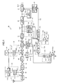
- FIG. 1 is a general block diagram of the FM tuner according to the present embodiment.
- An FM tuner 50 is formed on a common circuit board while having all main components designed as integrated circuits, and is essentially configured as an integrated tuner module.
- the module is incorporated as one component of a car audio device in an automotive vehicle, for example.
- An RF signal S RF received by an antenna 54 is processed in the FM tuner 50 by a signal processing system including an FM-RF tuned amplifier circuit 56, a first local oscillator unit 58, a first mixing circuit 60, bandpass filters (BPF) 62, 66, buffer amps 64, 72, a second local oscillator unit 68, a second mixing circuit 70, an IFBPF 74, a limiter amp 76, an FM detection circuit 78, a noise canceller 80, and a matrix circuit (MPX circuit) 82.
- An output signal S OUT corresponding to the audio signal of the desired station is generated.
- the FM tuner 50 includes a crystal oscillation circuit 90, an S-meter 92, a bandwidth control circuit 94, a stereo separation level control circuit 96, a pilot signal extraction circuit 98, a first adjacent-channel interference noise extraction circuit 100, a comparison circuit 102, a multipath noise extraction circuit 104, a control input generation circuit 106, a multipath reception detection unit 108, a second adjacent-channel interference noise extraction circuit 110, and a modulation level signal generation circuit 112. Also, the FM tuner 50 is connected to a system bus (not shown), and operates under the control of a microcomputer or other control unit (not shown) via the system bus.
- the RF signal S RF is input to the FM-RF tuned amplifier circuit 56.
- the FM-RF tuned amplifier circuit 56 attenuates the components out of the RF signal S RF that fall outside a band corresponding to a carrier wave frequency f R for the received target FM signal. Accordingly, the RF signal S RF in the band that includes the frequency f R for the preferred station is passed through the FM-RF tuned amplifier circuit 56, and the signal output from the FM-RF tuned amplifier circuit 56 is input to the first mixing circuit 60.
- the first local oscillator unit 58 has a first oscillator circuit 114 and a divider circuit 116.
- the first oscillator circuit 114 has a PLL circuit that uses an original oscillation signal So output by the crystal oscillation circuit 90.
- the PLL circuit outputs an oscillation signal S OSC1 with a frequency f OSC1 corresponding to the preferred station.
- the f OSC1 is controlled by a control unit, and the f OSC1 is set to ⁇ • (f R + f IF1 ), where ⁇ is the division ratio of the divider 116.
- the divider 116 divides the S OSC1 from the first oscillation circuit 114 by ⁇ , generates an S LO1 , and outputs to the first mixing circuit 60.
- the first mixing circuit 60 mixes the input RF signal S RF with the first local oscillation signal S LO1 input from the first local oscillation unit 58, and generates a first intermediate signal S IF1 .
- the frequency f LO1 for the S LO1 is adjusted to be convertible to a predetermined first intermediate frequency f IF1 by frequency conversion of the signal for the preferred station with a frequency f R included in the S RF into the S IF1 by the first mixing circuit 60.
- the first intermediate frequency f IF1 is set, for example, to 10.7 MHz.
- the S IF1 is input to the second mixing circuit 70 via the BPF 62, the buffer amp 64, and the BPF 66.
- the BPF 62 and 66 it is possible to configure the BPF 62 and 66 using a ceramic filter.
- the second local oscillation unit 68 in this embodiment has a divider 118 in order to generate the S LO2 .
- the divider 118 divides by 2 the oscillation signal output by the crystal oscillation circuit 90 with a frequency of, for example, 20.5 MHz; generates the S LO2 , and supplies the signal to the second mixing circuit 70.
- the second mixing circuit 70 mixes the first intermediate signal S IF1 input from the BPF 66 with the second local oscillation signal S LO2 input from the second local oscillation unit 68, and generates a second intermediate signal S IF2 with a second intermediate frequency f IF2 .
- the frequency f LO2 of the S LO2 is set to (f IF1 - f IF2 ), and the target reception signal with a frequency f IF1 included in the S IF1 is converted into a frequency f IF2 in the second mixing circuit 70.
- the second intermediate frequency f IF2 is set, for example, to 450 kHz.
- the S IF2 is input to the IFBPF 74 via the buffer amp 72.
- the IFBPF 74 is a bandpass filter that sets f IF2 as the center frequency and is capable of variably setting the pass bandwidth W F .
- the pass bandwidth W F of the IFBPF 74 is controlled by the bandwidth control circuit 94, as will be discussed hereafter.
- the S IF2 output from the IFBPF 74 is input to the FM detection circuit 78 via the limiter amp 76.
- the FM detection circuit 78 is composed of a quadrature detection circuit.
- the FM detection circuit 78 performs FM detection of the S IF2 input from the limiter amp 76, and outputs a detection output signal S DET .
- the noise canceller 80 removes pulse noise from the detection output signal S DET .
- the received signal can be overlaid with "pulse noise" with short time duration and high amplitude, caused by the operation of the car engine, electric mirrors, windshield wipers, and the like.
- the noise canceller 80 reduces sound quality degradation caused by pulse noise. Once the pulse noise has been removed the S DET is input to the matrix circuit 82.
- the pilot signal extraction circuit 98 is provided for the output of the noise canceller 80.
- the S DET is a stereo composite signal made up of an (L + R) signal, an (L - R) signal, and a pilot signal S PL .
- the pilot signal extraction circuit 98 extracts the pilot signal S PL from the S DET .
- the extracted pilot signal S PL is input to the matrix circuit 82.
- the matrix circuit 82 uses the pilot signal S PL input from the pilot signal extraction circuit 98 to cancel out the pilot signal S PL from the S DET , and it is possible to extract the (L+R) signal and the (L-R) signal, respectively.
- the stereo separation level control circuit 96 adjusts the relative strength of the difference signal (L-R) in relation to the sum signal (L+R) in the matrix process in the matrix circuit 82, and controls the stereo signal separation level.
- the S-meter circuit 92 generates a signal S M-AC corresponding to the fluctuation component included in the S IF1 on the basis of, e.g., the S IF1 input from the BPF 66; smoothes the fluctuation component using the LPF; and generates the reception field strength signal S M-DC .
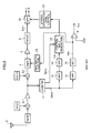
- FIG. 2 is a circuit diagram showing the general configuration of the S-meter circuit 92.
- the S-meter circuit 92 has six limiter amps 120-1 through 120-6 connected in-line, an accumulator 122 into which the output of the limiter amps 120-1 through 120-6 is input in parallel, a current mirror circuit 124 that extracts an output current I OUT from the accumulator 122 to the respective output circuits for the S M-DC and the S M-AC , and a smoothing circuit 126 that generates the S M-DC on the basis of the output current from the current mirror circuit 124.
- the S IF1 is input to the first limiter amp 120-1, and is amplified by each of the limiter amps 120 one after the other.
- An output signal S Ak from each limiter amp 120-k (where k is an integer with a value of 1 ⁇ k ⁇ 6) is input to the accumulator 122.
- the current mirror 124 has an input side channel through which the I OUT flows, and an output side channel provided in 2 parallel lines.
- the input side I OUT is replicated respectively in each output side channel.
- the smoothing circuit 126 composed of a resistor R 1 and a capacitor C 1 is provided on one output side channel.
- the smoothing circuit 126 has a large time constant, and generates the signal S M-DC , which is sufficiently smoothed and treated effectively as DC.
- the signal corresponding to the I OUT extracted to the other output side channel is output as the S M-AC , including a variety of variation components.
- the S M-AC is input to the first adjacent-channel interference noise extraction circuit 100 and the multipath noise extraction circuit 104.
- the first adjacent-channel interference noise extraction circuit 100 extracts noise components caused by adjacent-channel interference, including S M-AC .
- Adjacent-channel interference occurs in instances in which other stations exist at a frequency close to that of the preferred station, and interferes with favorable reception of the preferred station. If the RF frequency differential between the broadcast station causing adjacent-channel interference and the preferred station is represented as ⁇ f, a high-frequency component having a frequency corresponding to ⁇ f will be present in the S M-AC when adj acent-channel interference occurs.
- the first adjacent-channel interference noise extraction circuit 100 is composed of an HPF 130 and a detection circuit 132.
- a cutoff frequency f C in the HPF 130 is set to allow the main components of the adjacent-channel interference noise included in the S M-AC to pass through the HPF 130.
- the cutoff frequency f C of the HPF 130 can be set to around 100 kHz.
- the detection circuit 132 performs rectifying detection on the high-frequency component that has passed through the HPF 130 and converts the component to DC voltage.
- the first adjacent-channel interference noise extraction circuit 100 generates a DC signal S AI1 with a voltage level corresponding to the adjacent-channel interference noise component amount in the received signal.
- the S AI1 is used in the bandwidth control circuit 94 for switching between a wider or narrower pass-through bandwidth W F for the IFBPF 74, as will be discussed hereafter.
- the S AI1 is smoothed using a predetermined time constant. For instance, a time constant of about 2 mS is applied.
- the comparison circuit 102 compares the level of the adj acent-channel interference noise component S AI1 extracted by the first adjacent-channel interference noise extraction circuit 100 with a predetermined reference voltage V ref1 and determines whether an adjacent-channel interference state exists or not. Specifically, if S AI1 > V ref1 , a predetermined voltage V H (H level) corresponding to a logical value of "1" is output as the signal S SQ1 indicating a determination result that adjacent-channel interference has occurred. However, if S AI1 ⁇ V ref1 , a predetermined voltage V L (L level) corresponding to a logical value of "0" is output as the signal S SQ1 indicating a determination result that no adjacent-channel interference has occurred.
- the S SQ1 is sent to the microcomputer or other control unit via the system bus, and is used for AF search control.
- the multipath noise extraction circuit 104 is composed of an HPF 134 and a detection circuit 136.
- the cutoff frequency f C for the HPF 134 is set to allow the main components of the multipath noise included in the S M-AC to pass through the HPF 134. It is possible for f C to be set to about 50 kHz for FM radio broadcast.
- the detection circuit 136 performs rectifying detection on the high-frequency component that has passed through the HPF 134 and converts the component to a DC current. As a result, the multipath noise extraction circuit 104 generates a DC signal S MP with a voltage level corresponding to the multipath noise component amount in the received signal.
- the S MP is input to the control input generation circuit 106. As will be discussed hereafter, the S MP is used for generation of a control input signal S SC to the stereo separation level control circuit 96 and a multipath interference detection signal S SQ2 .
- Another output S M-DC from the S-meter circuit 92 is input to the control input generation circuit 106 and the bandwidth control circuit 94. Further discussion will follow.
- the second adjacent-channel interference noise extraction circuit 110 extracts the adjacent-channel interference noise component included in the output signal S DET from the FM detection circuit 78.
- the S DET when adjacent-channel interference occurs is overlaid with an audio band signal component corresponding to the preferred station, and has a high-frequency component having a frequency corresponding to the RF frequency differential ⁇ f between the preferred station and the interfering station.
- the second adjacent-channel interference noise extraction circuit 110 is composed of an HPF 138 and a detection circuit 140, and outputs a DC signal S AI2 with a voltage level corresponding to the strength of the high-frequency component produced by the adjacent-channel interference.
- the cutoff frequency f C for the HPF 138 can be set to about 100 kHz, as with the HPF 130.
- the S AI2 is input to the bandwidth control circuit 94.
- the modulation level signal generation circuit 112 generates a DC signal S MD with a voltage level corresponding to the modulation level of the received signal on the basis of the S DET .
- the modulation level signal generation circuit 112 is composed of an LPF 142 and a detection circuit 144. The circuit removes the high-frequency component caused by adjacent-channel interference, and the like, and outputs the DC signal S MD with a voltage level corresponding to the modulation level.
- the S MD is used by the bandwidth control circuit 94.
- the bandwidth control circuit 94 controls the bandwidth W F of the IFBPF 74 on the basis of the S M-DC generated by the S-meter circuit 92, the S AI1 generated by the first adjacent-channel interference noise extraction circuit 100, the S AI2 generated by the second adjacent-channel interference noise extraction circuit 110, and the S MD from the modulation level signal generation circuit 112. For example, the bandwidth control circuit 94 determines whether or not the adjacent-channel interference strength has exceeded a predetermined threshold value. Below the threshold value, the W F is set to a wider reference bandwidth so audio distortion will not occur. However, in an instance in which either the S AI1 or the S AI2 , or both, exceed the threshold value, the W F is narrowed from the reference bandwidth. As a result, it is possible to remove the adjacent-channel interference wave in the IFBPF 74.
- the bandwidth control circuit 94 sets the bandwidth W F narrower in a case in which the received signal strength is in a predetermined weak field state and in a predetermined low modulation level state, on the basis of the S M-DC and the S MD , even when the adjacent-channel interference strength is at or below a predetermined threshold value, for example.
- a predetermined threshold value for example.
- treble component noise that increases in a weak field state is removed by the IFBPF 74, and sensitivity is improved.
- audio distortion will readily occur if W F is narrowed. Therefore, in the case of a high modulation level, the bandwidth control circuit 94 sets the W F to the reference bandwidth, even in a weak field state, provided that adjacent-channel interference does not occur.
- the present FM tuner 50 reduces the auditory effect of audio distortion that can occur at this time through control of the separation level R SEP , which will be discussed hereafter.
- the control input generation circuit 106 generates the control input signal S SC to the stereo separation level control circuit 96 on the basis of the S M-DC corresponding to the reception field strength and the S MP corresponding to the multipath noise component amount.
- the control input generation circuit 106 attenuates the S M-DC in accordance with the S MP and generates the S SC .
- the control input generation circuit 106 has a function for smoothing the S SC using a predetermined time constant.
- the S SC generated by the control input generation circuit 106 will decline to a greater degree, when the electric field strength is weaker, and also when the fluctuation component corresponding to the multipath noise component is larger.
- the stereo separation level control circuit 96 lowers the separation level using the matrix circuit 82 in a case in which the S SC is low, and raises the level in a case in which the S MP is high.
- reproduction is performed with a reduced stereo separation level or as monaural reproduction.
- the effect of noise offensive to the ear at the time of a weak field and of multipath noise on stereo audio is reduced, and auditory irritation is diminished.
- the multipath reception detection unit 108 determines whether or not a multipath reception state exists in accordance with the level of the multipath noise extracted by the multipath noise extraction circuit 104.
- the multipath reception detection unit 108 has a comparison circuit 146 and a voltage source 148 for supplying a reference voltage V REF2 .
- the V REF2 is set to a predetermined threshold value.
- the comparison circuit 146 compares the S MP input from the multipath noise extraction circuit 104 with the V REF2 , and if S MP > V REF2 , for example, an H level corresponding to a logical value of "1" is output as the signal S SQ2 , indicating a determination result that multipath interference has occurred.
- S SQ2 is sent to the microcomputer or other control unit via the system bus, and is used for AF search control.
- the multipath reception detection unit 108 is input the signal S MP to which the time constant is not applied, not the output signal S SC of the control input generation circuit 106, to which a comparatively large time constant is applied. Accordingly, the multipath reception detection unit 108 is able to rapidly detect and determine whether or not a state change has occurred in the multipath reception state, and the AF search and the like utilizing the result can be accelerated.
- V REF2 can be variably set, or the control is performed from the control unit via the system bus.
- the multipath reception detection unit 108 can also be configured with an A/D converter for converting the S MP to a digital value D MP , and with a microcomputer for identifying the occurrence of multipath reception on the basis of the digital value D MP .
- the microcomputer can be configured with a control unit connected to the A/D converter via the system bus. The D MP is sent to the control unit via the system bus, and a decision is made via a calculation process in the control unit as to whether or not a correspondence exists with a multipath reception state in which the D MP exceeds a predetermined threshold value.
- adjacent-channel interference detection and multipath reception detection are performed in parallel on the basis of the amplitude fluctuation component S M-AC extracted from the FM reception signal by the S-meter circuit 92. Accordingly, it is possible to accelerate the AF search using both detection results.
- a portion of the circuitry for determining a multipath reception state has conventionally shared circuitry that extracts the multipath noise component for control input generation of the stereo separation level. This makes it possible to make only a minor enlargement of the FM tuner circuit scale, and minimize any increase in the size and cost of the IC chips that constitute the FM tuner.
- the FM tuner for controlling the stereo separation level during multipath reception has a multipath noise extraction circuit for extracting the multipath noise component in order to generate a control input signal to the stereo separation level control unit.
- the multipath noise extraction circuit is used as one part of the circuit configuration for detecting multipath interference. Accordingly, a configuration providing circuitry for detecting multipath interference can be obtained separately from the circuitry for detecting adjacent-channel interference, and with a smaller and simpler circuit configuration.
Landscapes
- Engineering & Computer Science (AREA)
- Computer Networks & Wireless Communication (AREA)
- Signal Processing (AREA)
- Noise Elimination (AREA)
- Stereo-Broadcasting Methods (AREA)
- Circuits Of Receivers In General (AREA)
Applications Claiming Priority (1)
| Application Number | Priority Date | Filing Date | Title |
|---|---|---|---|
| JP2007202707A JP4916974B2 (ja) | 2007-08-03 | 2007-08-03 | Fmチューナ |
Publications (3)
| Publication Number | Publication Date |
|---|---|
| EP2020753A2 true EP2020753A2 (fr) | 2009-02-04 |
| EP2020753A3 EP2020753A3 (fr) | 2010-01-13 |
| EP2020753B1 EP2020753B1 (fr) | 2012-11-21 |
Family
ID=40039785
Family Applications (1)
| Application Number | Title | Priority Date | Filing Date |
|---|---|---|---|
| EP08161574A Expired - Fee Related EP2020753B1 (fr) | 2007-08-03 | 2008-07-31 | Récepteur FM |
Country Status (4)
| Country | Link |
|---|---|
| US (1) | US7885628B2 (fr) |
| EP (1) | EP2020753B1 (fr) |
| JP (1) | JP4916974B2 (fr) |
| CN (1) | CN101359920B (fr) |
Cited By (1)
| Publication number | Priority date | Publication date | Assignee | Title |
|---|---|---|---|---|
| FR2944929A1 (fr) * | 2009-04-23 | 2010-10-29 | Continental Automotive France | Systeme a interface numerique pour la reception et le traitement numerique de signaux radiofrequence et procede associe |
Families Citing this family (11)
| Publication number | Priority date | Publication date | Assignee | Title |
|---|---|---|---|---|
| CN102124659B (zh) * | 2008-08-21 | 2014-02-26 | 英特赛尔美国股份有限公司 | 天线模块和利用该天线模块的噪声消除方法 |
| FR2954640B1 (fr) * | 2009-12-23 | 2012-01-20 | Arkamys | Procede d'optimisation de la reception stereo pour radio analogique et recepteur de radio analogique associe |
| JP2011172188A (ja) * | 2010-02-22 | 2011-09-01 | On Semiconductor Trading Ltd | ステレオ信号処理回路 |
| CN102332282A (zh) * | 2011-07-20 | 2012-01-25 | 深圳市君兰电子有限公司 | 一种dvd模组的性能检测方法及系统 |
| WO2013057801A1 (fr) * | 2011-10-19 | 2013-04-25 | パイオニア株式会社 | Appareil récepteur, procédé de réception, programme de réception et support d'enregistrement ayant stocké sur celui-ci un programme de réception |
| US9252899B2 (en) * | 2012-06-26 | 2016-02-02 | Ibiquity Digital Corporation | Adaptive bandwidth management of IBOC audio signals during blending |
| CN102843203B (zh) * | 2012-08-13 | 2017-03-15 | 泉州市琪祥电子科技有限公司 | 一种自动静噪电路 |
| JP6521826B2 (ja) * | 2015-10-14 | 2019-05-29 | 三菱電機株式会社 | 無線受信装置 |
| WO2017221403A1 (fr) * | 2016-06-24 | 2017-12-28 | 三菱電機株式会社 | Dispositif de réception radio |
| CN106992791A (zh) * | 2017-03-21 | 2017-07-28 | 合肥极友软件开发有限公司 | 一种抗干扰车载收音机系统 |
| CN107733544A (zh) * | 2017-11-02 | 2018-02-23 | 深圳市路畅科技股份有限公司 | 一种收音机和一种预设电台发射频率表的获取方法及装置 |
Family Cites Families (29)
| Publication number | Priority date | Publication date | Assignee | Title |
|---|---|---|---|---|
| US3662113A (en) * | 1968-03-27 | 1972-05-09 | Scott Inc H H | Stereophonic demodulator apparatus and automatic monophonic-stereophonic switching circuit |
| US4216353A (en) * | 1979-03-27 | 1980-08-05 | Mcintosh Laboratory, Inc. | Adaptive multiplex blend control for stereo decoder to maintain signal to noise ratio |
| JPS5646352U (fr) * | 1979-09-17 | 1981-04-25 | ||
| US4416024A (en) * | 1979-12-17 | 1983-11-15 | Sanyo Electric Co., Inc. | Distortion reducing circuit in FM receiver |
| US5204904A (en) * | 1986-12-01 | 1993-04-20 | Carver Corporation | Apparatus for receiving and processing frequency modulated electromagnetic signals |
| JPH0422584Y2 (fr) * | 1987-02-13 | 1992-05-25 | ||
| US5202924A (en) * | 1989-12-22 | 1993-04-13 | Allegro Microsystems, Inc. | Stereo FM radio receiver with variable band pass stereo decoder |
| JP2983609B2 (ja) * | 1990-10-31 | 1999-11-29 | 三洋電機株式会社 | マルチパスノイズ低減回路 |
| US5113446A (en) * | 1990-12-17 | 1992-05-12 | Ford Motor Company | Stereo blend controller for FM receivers |
| US5249233A (en) * | 1992-04-06 | 1993-09-28 | Ford Motor Company | Multipath noise minimizer for radio receiver |
| JP3622014B2 (ja) * | 1993-03-24 | 2005-02-23 | ブラウプンクト−ヴェルケ ゲゼルシャフト ミット ベシュレンクテル ハフツング | デジタル信号処理付き放送受信機 |
| WO1994022228A1 (fr) * | 1993-03-24 | 1994-09-29 | Blaupunkt-Werke Gmbh | Circuit pour la derivation d'un signal de qualite dependant de la qualite d'un signal multiplex de reception |
| DE4319457C2 (de) * | 1993-06-11 | 1997-09-04 | Blaupunkt Werke Gmbh | Schaltungsanordnung zur Nachbarkanalerkennung und -unterdrückung in einem FM-Rundfunkempfänger |
| JP2955497B2 (ja) * | 1995-08-31 | 1999-10-04 | 富士通テン株式会社 | ステレオ受信機 |
| DE19540183A1 (de) * | 1995-10-27 | 1997-04-30 | Bosch Gmbh Robert | Stereorundfunkempfänger |
| US5701345A (en) * | 1996-03-25 | 1997-12-23 | Delco Electronics Corporation | Multipath interference reduction system and method |
| JPH1188207A (ja) * | 1997-09-04 | 1999-03-30 | Kenwood Corp | Fm受信機におけるノイズキャンセラ |
| US6295324B1 (en) * | 1997-12-10 | 2001-09-25 | Visteon Global Technologies, Inc. | Signal quality measurement using full-complex FM detector |
| US6173166B1 (en) * | 1998-06-29 | 2001-01-09 | Visteon Global Technologies, Inc. | Detection and correction of multipath in an FM receiver |
| US6064865A (en) * | 1999-03-01 | 2000-05-16 | Ford Motor Company | Proportional diversity radio receiver system with dynamic noise-controlled antenna phasers |
| JP3368879B2 (ja) * | 1999-12-22 | 2003-01-20 | 三菱電機株式会社 | マルチパスノイズ除去装置、オーディオ出力装置およびfm受信機 |
| JP3911150B2 (ja) | 2001-11-16 | 2007-05-09 | 松下電器産業株式会社 | Fm受信機 |
| JP2004129162A (ja) * | 2002-10-07 | 2004-04-22 | Pioneer Electronic Corp | 受信方法及び受信装置 |
| JP4133604B2 (ja) * | 2003-06-10 | 2008-08-13 | アルパイン株式会社 | ラジオ受信機 |
| JP4088245B2 (ja) * | 2003-11-26 | 2008-05-21 | アルプス電気株式会社 | Fmチューナ |
| JP4444784B2 (ja) * | 2004-10-20 | 2010-03-31 | アルパイン株式会社 | 受信装置および受信方法 |
| CN101356753B (zh) | 2006-01-25 | 2012-11-07 | 三菱电机株式会社 | 接收装置 |
| JP2009081839A (ja) * | 2007-09-04 | 2009-04-16 | Sanyo Electric Co Ltd | Fmチューナ |
| JP2009105727A (ja) * | 2007-10-24 | 2009-05-14 | Sanyo Electric Co Ltd | Fm受信機 |
-
2007
- 2007-08-03 JP JP2007202707A patent/JP4916974B2/ja not_active Expired - Fee Related
-
2008
- 2008-07-31 EP EP08161574A patent/EP2020753B1/fr not_active Expired - Fee Related
- 2008-07-31 US US12/222,023 patent/US7885628B2/en not_active Expired - Fee Related
- 2008-08-01 CN CN2008101354154A patent/CN101359920B/zh not_active Expired - Fee Related
Non-Patent Citations (1)
| Title |
|---|
| None |
Cited By (1)
| Publication number | Priority date | Publication date | Assignee | Title |
|---|---|---|---|---|
| FR2944929A1 (fr) * | 2009-04-23 | 2010-10-29 | Continental Automotive France | Systeme a interface numerique pour la reception et le traitement numerique de signaux radiofrequence et procede associe |
Also Published As
| Publication number | Publication date |
|---|---|
| CN101359920A (zh) | 2009-02-04 |
| JP4916974B2 (ja) | 2012-04-18 |
| EP2020753B1 (fr) | 2012-11-21 |
| JP2009038700A (ja) | 2009-02-19 |
| US20090036085A1 (en) | 2009-02-05 |
| US7885628B2 (en) | 2011-02-08 |
| EP2020753A3 (fr) | 2010-01-13 |
| CN101359920B (zh) | 2012-09-05 |
Similar Documents
| Publication | Publication Date | Title |
|---|---|---|
| US7885628B2 (en) | FM tuner | |
| EP2034614B1 (fr) | Syntoniseur FM | |
| US5212827A (en) | Zero intermediate frequency noise blanker | |
| EP2053753B1 (fr) | Récepteur FM | |
| US7860479B2 (en) | FM receiver | |
| JP4235560B2 (ja) | チューナ用の自動利得制御 | |
| US4727580A (en) | Radio receiver | |
| EP0399557B1 (fr) | Récepteur FM stéréo | |
| JP2009273093A (ja) | Fm受信機 | |
| JP2009021721A (ja) | Fmチューナ | |
| JP4160269B2 (ja) | Fmラジオ受信機 | |
| JP3157281B2 (ja) | 受信機 | |
| JP2004297574A (ja) | 信号検出装置およびその装置を利用可能な受信装置 | |
| JP2008227751A (ja) | 車両用受信装置 | |
| JP2928041B2 (ja) | Fm受信機 | |
| WO2007066528A1 (fr) | Dispositif de détection de sensibilité de réception et dispositif de réception | |
| JP2009105729A (ja) | Fmラジオ受信機 | |
| JPH07193518A (ja) | Am受信機 | |
| JPH0856167A (ja) | 受信機の利得制御装置 | |
| EP1968202A1 (fr) | Appareil de détermination de sensibilité de réception | |
| JP2009147500A (ja) | ラジオ受信機 | |
| JP2007174517A (ja) | ダイバーシティ受信機 | |
| JPH0352260B2 (fr) | ||
| JPH0752865B2 (ja) | Fmステレオ放送受信機 | |
| JPH07105763B2 (ja) | Fmステレオ受信装置 |
Legal Events
| Date | Code | Title | Description |
|---|---|---|---|
| PUAI | Public reference made under article 153(3) epc to a published international application that has entered the european phase |
Free format text: ORIGINAL CODE: 0009012 |
|
| AK | Designated contracting states |
Kind code of ref document: A2 Designated state(s): AT BE BG CH CY CZ DE DK EE ES FI FR GB GR HR HU IE IS IT LI LT LU LV MC MT NL NO PL PT RO SE SI SK TR |
|
| AX | Request for extension of the european patent |
Extension state: AL BA MK RS |
|
| PUAL | Search report despatched |
Free format text: ORIGINAL CODE: 0009013 |
|
| AK | Designated contracting states |
Kind code of ref document: A3 Designated state(s): AT BE BG CH CY CZ DE DK EE ES FI FR GB GR HR HU IE IS IT LI LT LU LV MC MT NL NO PL PT RO SE SI SK TR |
|
| AX | Request for extension of the european patent |
Extension state: AL BA MK RS |
|
| RIC1 | Information provided on ipc code assigned before grant |
Ipc: H04B 1/10 20060101ALI20091205BHEP Ipc: H04B 1/16 20060101AFI20081202BHEP |
|
| 17P | Request for examination filed |
Effective date: 20100629 |
|
| 17Q | First examination report despatched |
Effective date: 20100730 |
|
| AKX | Designation fees paid |
Designated state(s): DE FR GB |
|
| RIC1 | Information provided on ipc code assigned before grant |
Ipc: H04B 1/10 20060101ALI20120306BHEP Ipc: H04B 1/16 20060101AFI20120306BHEP |
|
| GRAP | Despatch of communication of intention to grant a patent |
Free format text: ORIGINAL CODE: EPIDOSNIGR1 |
|
| GRAS | Grant fee paid |
Free format text: ORIGINAL CODE: EPIDOSNIGR3 |
|
| GRAA | (expected) grant |
Free format text: ORIGINAL CODE: 0009210 |
|
| RAP1 | Party data changed (applicant data changed or rights of an application transferred) |
Owner name: SANYO SEMICONDUCTOR CO., LTD. Owner name: SANYO ELECTRIC CO., LTD. |
|
| RIN1 | Information on inventor provided before grant (corrected) |
Inventor name: KOBAYASHI, KEIJI |
|
| AK | Designated contracting states |
Kind code of ref document: B1 Designated state(s): DE FR GB |
|
| RAP1 | Party data changed (applicant data changed or rights of an application transferred) |
Owner name: SANYO ELECTRIC CO., LTD. Owner name: SANYO SEMICONDUCTOR CO., LTD. |
|
| REG | Reference to a national code |
Ref country code: GB Ref legal event code: FG4D |
|
| REG | Reference to a national code |
Ref country code: DE Ref legal event code: R096 Ref document number: 602008020208 Country of ref document: DE Effective date: 20130117 |
|
| PGFP | Annual fee paid to national office [announced via postgrant information from national office to epo] |
Ref country code: GB Payment date: 20130624 Year of fee payment: 6 |
|
| PLBE | No opposition filed within time limit |
Free format text: ORIGINAL CODE: 0009261 |
|
| STAA | Information on the status of an ep patent application or granted ep patent |
Free format text: STATUS: NO OPPOSITION FILED WITHIN TIME LIMIT |
|
| 26N | No opposition filed |
Effective date: 20130822 |
|
| PGFP | Annual fee paid to national office [announced via postgrant information from national office to epo] |
Ref country code: DE Payment date: 20130731 Year of fee payment: 6 |
|
| PGFP | Annual fee paid to national office [announced via postgrant information from national office to epo] |
Ref country code: FR Payment date: 20130712 Year of fee payment: 6 |
|
| REG | Reference to a national code |
Ref country code: DE Ref legal event code: R097 Ref document number: 602008020208 Country of ref document: DE Effective date: 20130822 |
|
| REG | Reference to a national code |
Ref country code: DE Ref legal event code: R119 Ref document number: 602008020208 Country of ref document: DE |
|
| GBPC | Gb: european patent ceased through non-payment of renewal fee |
Effective date: 20140731 |
|
| REG | Reference to a national code |
Ref country code: FR Ref legal event code: ST Effective date: 20150331 |
|
| PG25 | Lapsed in a contracting state [announced via postgrant information from national office to epo] |
Ref country code: DE Free format text: LAPSE BECAUSE OF NON-PAYMENT OF DUE FEES Effective date: 20150203 |
|
| REG | Reference to a national code |
Ref country code: DE Ref legal event code: R119 Ref document number: 602008020208 Country of ref document: DE Effective date: 20150203 |
|
| PG25 | Lapsed in a contracting state [announced via postgrant information from national office to epo] |
Ref country code: FR Free format text: LAPSE BECAUSE OF NON-PAYMENT OF DUE FEES Effective date: 20140731 Ref country code: GB Free format text: LAPSE BECAUSE OF NON-PAYMENT OF DUE FEES Effective date: 20140731 |