EP2022650A1 - Luftreifen - Google Patents
Luftreifen Download PDFInfo
- Publication number
- EP2022650A1 EP2022650A1 EP08161762A EP08161762A EP2022650A1 EP 2022650 A1 EP2022650 A1 EP 2022650A1 EP 08161762 A EP08161762 A EP 08161762A EP 08161762 A EP08161762 A EP 08161762A EP 2022650 A1 EP2022650 A1 EP 2022650A1
- Authority
- EP
- European Patent Office
- Prior art keywords
- bead
- tire
- bead ring
- terminal end
- previous
- Prior art date
- Legal status (The legal status is an assumption and is not a legal conclusion. Google has not performed a legal analysis and makes no representation as to the accuracy of the status listed.)
- Withdrawn
Links
- 239000011324 bead Substances 0.000 claims abstract description 121
- 230000002787 reinforcement Effects 0.000 claims abstract description 27
- 229920001971 elastomer Polymers 0.000 claims abstract description 15
- 230000003014 reinforcing effect Effects 0.000 claims description 4
- 238000004519 manufacturing process Methods 0.000 description 4
- 229920001875 Ebonite Polymers 0.000 description 3
- 150000001875 compounds Chemical class 0.000 description 3
- 239000000835 fiber Substances 0.000 description 3
- 244000144992 flock Species 0.000 description 3
- 229910000831 Steel Inorganic materials 0.000 description 2
- 239000010959 steel Substances 0.000 description 2
- 229920000049 Carbon (fiber) Polymers 0.000 description 1
- 229920000742 Cotton Polymers 0.000 description 1
- 239000004677 Nylon Substances 0.000 description 1
- 230000002730 additional effect Effects 0.000 description 1
- 239000004760 aramid Substances 0.000 description 1
- 229920003235 aromatic polyamide Polymers 0.000 description 1
- 210000004899 c-terminal region Anatomy 0.000 description 1
- 239000004917 carbon fiber Substances 0.000 description 1
- 230000006835 compression Effects 0.000 description 1
- 238000007906 compression Methods 0.000 description 1
- 239000000806 elastomer Substances 0.000 description 1
- 239000011152 fibreglass Substances 0.000 description 1
- 239000000463 material Substances 0.000 description 1
- VNWKTOKETHGBQD-UHFFFAOYSA-N methane Chemical compound C VNWKTOKETHGBQD-UHFFFAOYSA-N 0.000 description 1
- 229920001778 nylon Polymers 0.000 description 1
- 239000002245 particle Substances 0.000 description 1
- 229920003207 poly(ethylene-2,6-naphthalate) Polymers 0.000 description 1
- 229920000728 polyester Polymers 0.000 description 1
- 239000011112 polyethylene naphthalate Substances 0.000 description 1
- 229920000139 polyethylene terephthalate Polymers 0.000 description 1
- 239000005020 polyethylene terephthalate Substances 0.000 description 1
- 239000012783 reinforcing fiber Substances 0.000 description 1
- 238000004804 winding Methods 0.000 description 1
Images


Classifications
-
- B—PERFORMING OPERATIONS; TRANSPORTING
- B60—VEHICLES IN GENERAL
- B60C—VEHICLE TYRES; TYRE INFLATION; TYRE CHANGING; CONNECTING VALVES TO INFLATABLE ELASTIC BODIES IN GENERAL; DEVICES OR ARRANGEMENTS RELATED TO TYRES
- B60C15/00—Tyre beads, e.g. ply turn-up or overlap
- B60C15/02—Seating or securing beads on rims
- B60C15/024—Bead contour, e.g. lips, grooves, or ribs
- B60C15/0247—Bead contour, e.g. lips, grooves, or ribs with reverse bead seat inclination, i.e. the axially inner diameter of the bead seat is bigger than the axially outer diameter thereof
-
- B—PERFORMING OPERATIONS; TRANSPORTING
- B60—VEHICLES IN GENERAL
- B60C—VEHICLE TYRES; TYRE INFLATION; TYRE CHANGING; CONNECTING VALVES TO INFLATABLE ELASTIC BODIES IN GENERAL; DEVICES OR ARRANGEMENTS RELATED TO TYRES
- B60C15/00—Tyre beads, e.g. ply turn-up or overlap
- B60C15/0009—Tyre beads, e.g. ply turn-up or overlap features of the carcass terminal portion
- B60C15/0018—Tyre beads, e.g. ply turn-up or overlap features of the carcass terminal portion not folded around the bead core, e.g. floating or down ply
-
- B—PERFORMING OPERATIONS; TRANSPORTING
- B60—VEHICLES IN GENERAL
- B60C—VEHICLE TYRES; TYRE INFLATION; TYRE CHANGING; CONNECTING VALVES TO INFLATABLE ELASTIC BODIES IN GENERAL; DEVICES OR ARRANGEMENTS RELATED TO TYRES
- B60C15/00—Tyre beads, e.g. ply turn-up or overlap
- B60C15/0009—Tyre beads, e.g. ply turn-up or overlap features of the carcass terminal portion
- B60C15/0027—Tyre beads, e.g. ply turn-up or overlap features of the carcass terminal portion with low ply turn-up, i.e. folded around the bead core and terminating at the bead core
-
- B—PERFORMING OPERATIONS; TRANSPORTING
- B60—VEHICLES IN GENERAL
- B60C—VEHICLE TYRES; TYRE INFLATION; TYRE CHANGING; CONNECTING VALVES TO INFLATABLE ELASTIC BODIES IN GENERAL; DEVICES OR ARRANGEMENTS RELATED TO TYRES
- B60C17/00—Tyres characterised by means enabling restricted operation in damaged or deflated condition; Accessories therefor
- B60C17/0009—Tyres characterised by means enabling restricted operation in damaged or deflated condition; Accessories therefor comprising sidewall rubber inserts, e.g. crescent shaped inserts
-
- B—PERFORMING OPERATIONS; TRANSPORTING
- B60—VEHICLES IN GENERAL
- B60C—VEHICLE TYRES; TYRE INFLATION; TYRE CHANGING; CONNECTING VALVES TO INFLATABLE ELASTIC BODIES IN GENERAL; DEVICES OR ARRANGEMENTS RELATED TO TYRES
- B60C15/00—Tyre beads, e.g. ply turn-up or overlap
- B60C15/0009—Tyre beads, e.g. ply turn-up or overlap features of the carcass terminal portion
- B60C2015/009—Height of the carcass terminal portion defined in terms of a numerical value or ratio in proportion to section height
Definitions
- the present invention relates to a pneumatic radial tire, and more particularly, to the structure of the beads and carcass reinforcement means of the pneumatic radial tire.
- a tire with a radial carcass reinforcement usually comprises a reinforcing bead core in each bead portion of the tire, about which the carcass reinforcement is anchored by winding or forming an upturn.
- the bead cores provide a clamping force for the tire when the tire is mounted upon the beads seats of a wheel rim.
- the clamping produces a certain compression of the bead portion between the bead core and the wheel rim, the clamping generally being brought about by a difference in the angles of the bead seat and the rim seat respectively, and/or by a difference in the diameters of said seats.
- the bead clamping force of the tire is particularly important in designing a run-flat tire or tire system.
- One such tire system that uses the clamping force to maintain operation of the tire during underinflated or uninflated operating conditions is disclosed in US-A- 5,785,781 and US-A- 5,971,047 .
- the radial carcass reinforcement of the tire which is anchored within each bead to at least one inextensible annular reinforcement element, has a profile, when the tire is mounted on its operating rim and inflated to its operating pressure, with a direction of curvature which is constant in the sidewalls and bead regions which ends in the bead toe.
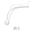
- the preferred bead region of this type of tire is more fully disclosed in US-A- 5,971,047 , wherein the carcass reinforcement has a hooking structure, and which is also shown in Figure 5 .
- the beads of the tire remain in place when traveling because the structure creates an increase of the clamping of the bead toe on the mounting rim as a function of the tension of the carcass reinforcement.
- the structure also makes it possible to have initial clamping on rim of low value, given that said clamping will increase when the tire is inflated to its recommended pressure.
- the above tire structure is complicated and difficult to manufacture in an accurate and consistent basis.
- the tire structure requires the use of non-standard tire building machinery such as special tire building drums.
- a simpler tire structure design that does not require special tire building machinery yet retains the bead clamping benefits is desired.
- the present invention is directed toward a tire according to claim 1.
- said tire is a pneumatic run-flat tire.
- claims refer to preferred embodiments of the invention.
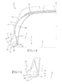
- FIG. 1 illustrates as one embodiment of the invention one half of a pneumatic tire 10 capable of operating during reduced inflation pressure conditions; this type of tire is often referred to as a self-supporting tire or run-flat tire.
- the tire 10 has at least one radial carcass reinforcement ply 12 that extends from one bead portion 14 to an opposing bead portion, passing through the crown region of the tire 10.
- the carcass reinforcement ply 12 is formed of parallel reinforcing cords; the cords are preferably inclined at angles of between 65° to 90° with respect to the equatorial plane EP of the tire 10.
- the belt structure 16 preferably has at least two plies of reinforcing cords.
- the cords in each ply are preferably crossed, relative to the cords in the adjacent belt ply.
- the bead portion 14 has an outer cross-sectional profile wherein as the profile moves from the axially outer side of the bead portion 14 to the axially inner side, the bead profile slopes radially upward, resulting in the bead toe 18 being both axially outward and radially inward of the bead heel 20.
- a rib 22 that assists in locking the tire onto a wheel rim having a correspondingly profiled bead rim seat.
- the bead portion 14 contains therein a bead ring 24.
- the illustrated bead ring 24 has a circular configuration and is formed of a plurality of steel wires or cords. However, the ring 24 may have a different cross-sectional configuration and be formed from alternative materials.
- the bead ring 24 is located within a preferably hard elastomeric component 26; the elastomeric component 26 surrounds the bead ring 24 all on sides and the geometric center C of the bead ring 24 is preferably axially offset from the axial center of the component 26, as measured along the greatest width of the component 26.
- the axial offset may be in a range of 2 to 10 mm such as 3 to 6 mm.
- the component 26 preferably extends radially upwards in an essentially triangular like fashion.
- the carcass reinforcement ply 12 has a main portion 28 extending about the main toroidal portion of the tire 10.
- the turn-up portions 30 of the carcass reinforcement ply 12 are the outer ends of the reinforcement ply 12, each turn-up portion 30 passes radially under the bead ring 24 and component 26.
- the reinforcement ply main portion 28 is expanded radially outward. As the main portion 28 expands, it pulls on the turnup portion 30, pulling the bead toe 18 radially inward into the wheel rim and flange, effectively acting to lock the bead portion 14 of the tire 10 onto the wheel.
- the turn-up portion 30 of the carcass reinforcement ply 12 extends from axially inward of the bead ring 24 to axially outward of the bead ring 24, and extends radially outward along the axially outer side of the component 26.
- the terminal end 32 of turn-up portion 30 is located radially inward of a line P, the line P being parallel to the bead base line B and spaced a distance Dt from the radially outermost location of the bead ring 24.
- the distance Dt may range from zero to 2 times the diameter Db of the bead ring 24.
- the terminal end 32 of the ply 12 is positioned so that it is axially spaced from the ply in the downturn portion 12a.
- the axial spacing is greater than or equal to the bead ring width. This limitation on the location of the terminal end 32 limits the terminal end 32 to a location near the bead core. In the illustrated tire, as the component 26 has a radial height greater than distance Dt outward of the bead ring 24, the component 26 is not fully enveloped by the turn-up portion 30.
- each tire side preferably axially inward of the main carcass portion 28, there is preferably at least one insert 34.
- the insert 34 has a curved configuration with the middle third of the insert 34 having a substantially constant thickness and the ends of the insert 34 being tapered.
- the insert 34 extends from the bead portion 14 to radially inward of the belt structure 16. When the insert 34 extends through the entire sidewall, it has a radially inner end located axially inward of the bead ring 24.
- the insert 34 is formed from a hard rubber, with a Shore A hardness at 100° C in a range of 55 to 90, with a preferred range of 60 to 70.
- the properties disclosed in US-A- 6,230,773 are suitable for the insert 34 of the present invention.
- the properties may be achieved by the compound disclosed in this reference, or other compounds may be selected which yield the disclosed properties.
- the rubber forming the insert 34 may also be flock loaded or blended with reinforcing fibers. Fibers useful may be either natural or man-made, and are characterized by having a length at least 100 times its diameter or width. Flock are particles smaller than fibers. And either may be formed from cotton, aramid, nylon, polyester, PET, PEN, carbon fiber, steel, fiberglass, or any combination thereof.
- the fiber or flock loading of the rubber is in the range of 5 to 35 parts per hundred parts rubber.
- the insert's lenticular configuration maintains the carcass main portion in a desired configuration.
- the reinforcement ply turn-up 30 passes radially inward of the bead ring 24, along the outer surface of the component 26, with the terminal end located axially outward of the bead ring 24 and radially inward of the line P.
- the turn-up portion 30 does not pass back under the bead ring 24, nor is it located within, or sandwiched or enveloped by the component 26.
- the reinforcement ply turn-up 30 passes under the bead ring 24 and has its terminal end 32 radially inward of the bead ring 24 and axially outward of the geometric center of the bead ring 24.
- the rubber component 26 is illustrated as a single component in which the bead ring 24 is embedded. When formed as a single component, the component 26 replaces the conventional apex and the hard rubber talon. To vary the stiffness characteristics of the bead region 14, the component 26 may be formed as using multiple elastomeric compounds.
- the bead region 14 of FIG. 3 shows the region partially enveloped by the carcass reinforcement ply 12 and containing the bead ring 24 therein is formed of two different rubber elements 36, 38.
- the upper element 36 i.e.
- the apex is radially outward of the radially outermost point of the bead ring 24 and has a flat base that extends radially inward of the line P.
- the lower element 38 i.e. the talon, fully encompasses the bead ring 24.
- the lower element 38 is formed from an elastomer having a greater Shore A hardness than that of the upper element 36.
- the tire 10 provides for greater ease in manufacturing and also providing for improved uniformity in the tire manufacturing as the turn-up portion location can be readily seen by the tire builder when assembling the bead portion 14 of the tire. Additionally, the tire bead portion may be assembled without having to expand the tire prior to assembly of the bead portion.
- the opposing bead rings 24 and sidewalls 40 may have an identical diameter and height, respectively; that is, the non-illustrated portion of the tire is a mirror image of that illustrated.
- the tire of FIG. 4 has a short sidewall 50 with a bead ring 52 of relatively greater diameter D BS , and a long sidewall 54 with a bead ring 56 of relatively smaller diameter D BNS .
- the tire is mounted on a tire rim having corresponding offset rim diameters to accommodate the different bead diameters.
Landscapes
- Engineering & Computer Science (AREA)
- Mechanical Engineering (AREA)
- Tires In General (AREA)
Applications Claiming Priority (1)
| Application Number | Priority Date | Filing Date | Title |
|---|---|---|---|
| US11/834,185 US20090038731A1 (en) | 2007-08-06 | 2007-08-06 | Pneumatic Run-Flat Tire |
Publications (1)
| Publication Number | Publication Date |
|---|---|
| EP2022650A1 true EP2022650A1 (de) | 2009-02-11 |
Family
ID=39828962
Family Applications (1)
| Application Number | Title | Priority Date | Filing Date |
|---|---|---|---|
| EP08161762A Withdrawn EP2022650A1 (de) | 2007-08-06 | 2008-08-04 | Luftreifen |
Country Status (2)
| Country | Link |
|---|---|
| US (1) | US20090038731A1 (de) |
| EP (1) | EP2022650A1 (de) |
Families Citing this family (1)
| Publication number | Priority date | Publication date | Assignee | Title |
|---|---|---|---|---|
| US20220185017A1 (en) * | 2020-12-16 | 2022-06-16 | The Goodyear Tire & Rubber Company | Non-pneumatic tire |
Citations (6)
| Publication number | Priority date | Publication date | Assignee | Title |
|---|---|---|---|---|
| JPS59106304A (ja) * | 1982-12-09 | 1984-06-20 | Yokohama Rubber Co Ltd:The | 空気入り安全タイヤ |
| US5785781A (en) | 1992-11-12 | 1998-07-28 | Compagnie Generale Des Etablissements Michelin | Radial tire with axially outer bead tip |
| US5971047A (en) | 1994-02-28 | 1999-10-26 | Compagnie Generale Des Etablissements Michelin-Michelin & Cie | Tire having beads of specified structure and assembly of rim and bearing support with same |
| US6230773B1 (en) | 1998-03-17 | 2001-05-15 | The Goodyear Tire & Rubber Company | Tire with sidewall carcass reinforcement |
| WO2002002355A1 (fr) * | 2000-07-03 | 2002-01-10 | Societe De Technologie Michelin | Pneumatique avec des bourrelets de structure amelioree |
| EP1674295A2 (de) * | 2004-12-22 | 2006-06-28 | The Goodyear Tire & Rubber Company | Notlaufreifen |
Family Cites Families (1)
| Publication number | Priority date | Publication date | Assignee | Title |
|---|---|---|---|---|
| FR2788238B1 (fr) * | 1999-01-13 | 2001-02-16 | Michelin Soc Tech | Pneumatique avec des bourrelets de structure amelioree |
-
2007
- 2007-08-06 US US11/834,185 patent/US20090038731A1/en not_active Abandoned
-
2008
- 2008-08-04 EP EP08161762A patent/EP2022650A1/de not_active Withdrawn
Patent Citations (7)
| Publication number | Priority date | Publication date | Assignee | Title |
|---|---|---|---|---|
| JPS59106304A (ja) * | 1982-12-09 | 1984-06-20 | Yokohama Rubber Co Ltd:The | 空気入り安全タイヤ |
| US5785781A (en) | 1992-11-12 | 1998-07-28 | Compagnie Generale Des Etablissements Michelin | Radial tire with axially outer bead tip |
| US5971047A (en) | 1994-02-28 | 1999-10-26 | Compagnie Generale Des Etablissements Michelin-Michelin & Cie | Tire having beads of specified structure and assembly of rim and bearing support with same |
| US6626220B1 (en) * | 1994-02-28 | 2003-09-30 | COMPAGNIE GéNéRALE DES ETABLISSEMENTS MICHELIN - MICHELIN & CIE | Tire having beads of specified structure |
| US6230773B1 (en) | 1998-03-17 | 2001-05-15 | The Goodyear Tire & Rubber Company | Tire with sidewall carcass reinforcement |
| WO2002002355A1 (fr) * | 2000-07-03 | 2002-01-10 | Societe De Technologie Michelin | Pneumatique avec des bourrelets de structure amelioree |
| EP1674295A2 (de) * | 2004-12-22 | 2006-06-28 | The Goodyear Tire & Rubber Company | Notlaufreifen |
Also Published As
| Publication number | Publication date |
|---|---|
| US20090038731A1 (en) | 2009-02-12 |
Similar Documents
| Publication | Publication Date | Title |
|---|---|---|
| US5263526A (en) | Pneumatic tire having specified bead structure | |
| US6913052B2 (en) | Tire with composite ply structure and method of manufacture | |
| US20220063353A1 (en) | Tire for vehicle comprising a stiffening structure | |
| EP1671814A1 (de) | Asymmetrischer Notlaufluftreifen | |
| EP2308694A1 (de) | Luftreifen | |
| US20030111152A1 (en) | Pneumatic tire bead area construction for improved chafer cracking resistance during run-flat operation | |
| US6719029B2 (en) | Tire wall gauges to optimize runflat tire ride comfort | |
| EP1638787B1 (de) | Pannenlauffähiger luftreifen | |
| JP4308329B2 (ja) | 改良型非膨張ハンドリング付きランフラットタイヤ | |
| US6276416B1 (en) | Run-flat tire with pair of rigid rings in shoulders inside carcass | |
| US7448422B2 (en) | Pneumatic run-flat tire | |
| EP1422079B1 (de) | Reifen mit neuem Wulstkern | |
| JP4394292B2 (ja) | 可動性が拡張されたタイヤ用の補強ウェッジインサート構造 | |
| US7281558B2 (en) | Run-flat tire with variable rigidity sidewalls | |
| US5423366A (en) | Heavy duty radial tire wherein bead toe lifting is prevented | |
| EP2022650A1 (de) | Luftreifen | |
| EP1674295A2 (de) | Notlaufreifen | |
| WO2008073885A2 (en) | Pneumatic run-flat tire | |
| EP1433590A2 (de) | Luftreifen mit einer Karkassenverbundstruktur und Verfahren zu dessen Herstellung | |
| US5151141A (en) | Tire and rim | |
| JP2006502906A (ja) | 対称的な荷重分布を有するビードを備えた長期移動性タイヤ | |
| US8567465B2 (en) | Self-supporting pneumatic tire | |
| US7004218B1 (en) | Pneumatic tire with specified carcass ply turn-up | |
| US20190061439A1 (en) | Bead structure for a pneumatic tire | |
| CA2503170A1 (en) | Pneumatic run-flat tire |
Legal Events
| Date | Code | Title | Description |
|---|---|---|---|
| PUAI | Public reference made under article 153(3) epc to a published international application that has entered the european phase |
Free format text: ORIGINAL CODE: 0009012 |
|
| AK | Designated contracting states |
Kind code of ref document: A1 Designated state(s): AT BE BG CH CY CZ DE DK EE ES FI FR GB GR HR HU IE IS IT LI LT LU LV MC MT NL NO PL PT RO SE SI SK TR |
|
| AX | Request for extension of the european patent |
Extension state: AL BA MK RS |
|
| 17P | Request for examination filed |
Effective date: 20090811 |
|
| 17Q | First examination report despatched |
Effective date: 20090904 |
|
| AKX | Designation fees paid |
Designated state(s): DE FR IT |
|
| GRAP | Despatch of communication of intention to grant a patent |
Free format text: ORIGINAL CODE: EPIDOSNIGR1 |
|
| GRAC | Information related to communication of intention to grant a patent modified |
Free format text: ORIGINAL CODE: EPIDOSCIGR1 |
|
| STAA | Information on the status of an ep patent application or granted ep patent |
Free format text: STATUS: THE APPLICATION IS DEEMED TO BE WITHDRAWN |
|
| 18D | Application deemed to be withdrawn |
Effective date: 20100923 |