EP2025869B1 - Aube de turbine à gaz avec structure de refroidissement interne - Google Patents
Aube de turbine à gaz avec structure de refroidissement interne Download PDFInfo
- Publication number
- EP2025869B1 EP2025869B1 EP07113996A EP07113996A EP2025869B1 EP 2025869 B1 EP2025869 B1 EP 2025869B1 EP 07113996 A EP07113996 A EP 07113996A EP 07113996 A EP07113996 A EP 07113996A EP 2025869 B1 EP2025869 B1 EP 2025869B1
- Authority
- EP
- European Patent Office
- Prior art keywords
- passage
- cooling
- blade
- trip strips
- cooling structure
- Prior art date
- Legal status (The legal status is an assumption and is not a legal conclusion. Google has not performed a legal analysis and makes no representation as to the accuracy of the status listed.)
- Active
Links
Images


Classifications
-
- F—MECHANICAL ENGINEERING; LIGHTING; HEATING; WEAPONS; BLASTING
- F01—MACHINES OR ENGINES IN GENERAL; ENGINE PLANTS IN GENERAL; STEAM ENGINES
- F01D—NON-POSITIVE DISPLACEMENT MACHINES OR ENGINES, e.g. STEAM TURBINES
- F01D5/00—Blades; Blade-carrying members; Heating, heat-insulating, cooling or antivibration means on the blades or the members
- F01D5/12—Blades
- F01D5/14—Form or construction
- F01D5/18—Hollow blades, i.e. blades with cooling or heating channels or cavities; Heating, heat-insulating or cooling means on blades
- F01D5/187—Convection cooling
-
- F—MECHANICAL ENGINEERING; LIGHTING; HEATING; WEAPONS; BLASTING
- F05—INDEXING SCHEMES RELATING TO ENGINES OR PUMPS IN VARIOUS SUBCLASSES OF CLASSES F01-F04
- F05D—INDEXING SCHEME FOR ASPECTS RELATING TO NON-POSITIVE-DISPLACEMENT MACHINES OR ENGINES, GAS-TURBINES OR JET-PROPULSION PLANTS
- F05D2230/00—Manufacture
- F05D2230/20—Manufacture essentially without removing material
- F05D2230/21—Manufacture essentially without removing material by casting
- F05D2230/211—Manufacture essentially without removing material by casting by precision casting, e.g. microfusing or investment casting
-
- F—MECHANICAL ENGINEERING; LIGHTING; HEATING; WEAPONS; BLASTING
- F05—INDEXING SCHEMES RELATING TO ENGINES OR PUMPS IN VARIOUS SUBCLASSES OF CLASSES F01-F04
- F05D—INDEXING SCHEME FOR ASPECTS RELATING TO NON-POSITIVE-DISPLACEMENT MACHINES OR ENGINES, GAS-TURBINES OR JET-PROPULSION PLANTS
- F05D2250/00—Geometry
- F05D2250/30—Arrangement of components
- F05D2250/31—Arrangement of components according to the direction of their main axis or their axis of rotation
- F05D2250/313—Arrangement of components according to the direction of their main axis or their axis of rotation the axes being perpendicular to each other
-
- F—MECHANICAL ENGINEERING; LIGHTING; HEATING; WEAPONS; BLASTING
- F05—INDEXING SCHEMES RELATING TO ENGINES OR PUMPS IN VARIOUS SUBCLASSES OF CLASSES F01-F04
- F05D—INDEXING SCHEME FOR ASPECTS RELATING TO NON-POSITIVE-DISPLACEMENT MACHINES OR ENGINES, GAS-TURBINES OR JET-PROPULSION PLANTS
- F05D2260/00—Function
- F05D2260/20—Heat transfer, e.g. cooling
- F05D2260/221—Improvement of heat transfer
- F05D2260/2212—Improvement of heat transfer by creating turbulence
-
- F—MECHANICAL ENGINEERING; LIGHTING; HEATING; WEAPONS; BLASTING
- F05—INDEXING SCHEMES RELATING TO ENGINES OR PUMPS IN VARIOUS SUBCLASSES OF CLASSES F01-F04
- F05D—INDEXING SCHEME FOR ASPECTS RELATING TO NON-POSITIVE-DISPLACEMENT MACHINES OR ENGINES, GAS-TURBINES OR JET-PROPULSION PLANTS
- F05D2260/00—Function
- F05D2260/20—Heat transfer, e.g. cooling
- F05D2260/221—Improvement of heat transfer
- F05D2260/2214—Improvement of heat transfer by increasing the heat transfer surface
- F05D2260/22141—Improvement of heat transfer by increasing the heat transfer surface using fins or ribs
Definitions
- the present invention relates to cast rotating blades for a gas turbine, and in particular to the design of an internal cooling structure within the blade.
- Turbine blades for gas turbines are designed and manufactured to withstand high temperatures during the gas turbine operation.
- Such turbine blades comprise an internal cooling structure through which a cooling fluid, typically air, is passed. Cooling air is typically bled from a compressor of the gas turbine engine. This extraction of air however, reduces the overall performance of the engine.
- the internal blade cooling structure is designed for optimal cooling efficiency.
- Such designs are disclosed for example in US 6,139,269 , US 6,634,858 and US 5,403,159 .
- Each is individually designed having complex arrangements of serpentine cooling structures including several passages extending in the blade longitudinal direction.
- the cooling structures furthermore comprise a multitude of trip strips arranged on the walls of the longitudinal passages, all of which oriented at approximately 45° to the direction of flow through the passage.
- Turbine blades with internal cooling structure of this type are cast, as a rule, by an investment casting process using a core defining the cooling structure.
- the core is made of a leachable material such as ceramic. Following the molding process, the ceramic core is removed from the blade by a leaching process.
- a gas turbine rotating blade comprises an internal cooling structure having at least three cooling passages extending in the blade longitudinal direction, at least one inlet opening in the region of the blade root, and at least one outlet opening in the region of the blade tip leading from a cooling passage out of the blade.
- the blade furthermore comprises in its root region a plenum for cooling air, the inlet opening extending from this plenum to a cooling passage.
- the first cooling passage extends, in the direction of cooling fluid, from the blade root region to the blade tip region.
- the second cooling passage extends from the tip to the root region.
- First and second cooling passages are in fluid connection with one another in the region of the blade tip by means of a bend or turn in the region of the blade tip.
- the third cooling passage again extends from the root to the tip, while second and third cooling passages are in fluid connection with one another by means of a turn or bend in the region of the blade root.
- US 4,728,400 discloses a gas turbine blade having several cooling passages, of which a first cooling passage comprises trip strips arranged at a 90° angle to the direction of cooling flow through the passage.
- an opening is provided in the cooling structure wall extending from the plenum to the bend or turn in the blade root region from the second to the third cooling passage.
- the opening provides a direct fluid connection from the bend to the root of the blade and to the exterior of the blade.
- the opening and root region of the blade is such that a liquid fluid is allowed to flow directly and essentially in the longitudinal blade direction out of the blade internal cooling structure. This allows the fluid core material to exit the blade completely without having to pass through any back turns or dead zones. Thus, it is prevented that fluid core material remains in the structure as residual fluid. The flow of cooling air through the internal cooling structure when the blade is in operation is thus assured.
- the opening at the bend or 180° turn of the internal structure is not closed up again prior to the operation of the blade in the turbine. Since said opening at the 180° turn has an effect on the aerodynamics of the internal cooling structure and distribution of the cooling air, the design of the cooling passages is adapted and optimized accordingly in view of cooling function and efficiency.
- the first cooling passage extending, in the direction of cooling fluid from the plenum in the root region to the tip region of the blade, comprises a plurality of turbulators or trip strips arranged at an angle of 90 ⁇ 10° to the direction of flow of the cooling fluid.
- the second cooling passage in fluid connection with the first cooling passage by means of a turn, comprises a plurality of trip strips or turbulators.
- the trip strips in the first and second cooling passages are arranged and dimensioned such that the ratio between their height and the distance between adjacent trip strips is 10 ⁇ 2.
- the trip strips in the second cooling passage are arranged at an angle of 45° ⁇ 10° in relation to the flow direction.
- the third cooling passage comprises a plurality of trip strips arranged at an angle of 45° ⁇ 10° from the direction of flow to the direction of the trip strip.
- the opening at the turn from the second to the third passage affects the cooling air distribution in the cooling structure.
- a non-plugged opening at that location would result in a reduction of the airflow from the plenum in the root region through the first and second passage and an increase of airflow from the plenum through the opening directly to the third passage.
- the design measures according to the invention in the form of a particular arrangement of trip strips in the first and second passage allow an optimization of the cooling airflow and re-establishment of the airflow through the first and second passage. It thereby assures sufficient and uniform cooling of the entire blade.
- the design of the trip strips according to the invention allows compensation of very small hydraulic pressure losses from the beginning of the first passage to the beginning of the third passage. Compensation of the low-pressure losses is achieved by pumping forces in the first and second passages due to a convective temperature increase of the cooling air along these passages.
- the design of the blade cooling structure according to the invention allows for optimized manufacturing due to the opening provided in the turn near the root of the blade.
- the design requires no measures following the casting for closing of the opening.
- the specific design of the trips strips in the cooling passages compensates for hydraulic pressure losses and thereby assures sufficient cooling within the first and second passages.
- the design therefore allows improved and simplified manufacturing while maintaining cooling performance.
- Figure 1 shows a rotating gas turbine blade 1 extending longitudinally from a blade root 2 to a blade tip section 3.
- Figure 2 shows the internal cooling structure of the blade having a plenum 4 within the root region for cooling air entering the cooling structure, a plurality of at least three longitudinal cooling passages 5-7 extending from the plenum 4 at the root 2 to the tip 3, from the tip section 3 to the root 2, and from the root to the tip section 3, respectively.
- the longitudinal passages are in fluid connection with one another by means of turns 9 and 10 of approximately 180°.
- the airflow passes, as indicated by arrows, from the plenum 4 through an inlet opening 8 at the beginning of the first cooling passage 5 (position A) to the end of the first passage at the tip of the blade (position B), and around a turn 9 of approximately 180°. It then flows along the second cooling passage 6 to a further 180° turn 10 (position C) connecting the second cooling passage 6 with the third cooling passage 7.
- the cooling air finally flows through the third cooling passage 7 to the tip of the blade and exits the cooling structure through an outlet opening 11 at the tip of the blade.
- an opening or channel 12 is provided for leaching out core material after casting and allowing all of the dissolved core material to run out of the cooling structure via the plenum 4 such that no core material remains in the turn 10.
- the opening 12 is left open during operation of the gas turbine. Through this opening 12, cooling air could pass more readily from the plenum 4 directly to the third cooling passage 7 rather than through first and second cooling passages 5 and 6.
- the pressure drop between position A and position B is such that a cooling airflow is assured through passages 5 and 6.
- a pressure loss is due to hydraulic resistance and depends on the square of the air velocity, the shape of the channel, the degree of smoothness of the passage walls as well as the shape of turbulators or trip strips.
- the features according to the invention result in that the air pressure at position C at the beginning of the third passage 7 is lower than at position A at the beginning of the first passage 5.
- a pumping effect occurs due to the rotation of the blade during turbine operation. Due to the pumping effect the air pressure increases with increasing radius of the passage, specifically in proportion to the difference of the squares of the radii at a given angular speed. In the first passage 5 therefore, the pressure increases with increasing radius from position A to position B. In the second passage 6, the pressure decreases with decreasing radius from position B to position C, decreasing by the same magnitude as it increased in passage 5. The final effect would therefore be zero. Additionally however, a heat flux is picked up by the cooling air from the heat convective walls of the passages increasing the temperature of the cooling air. As a result, the temperature of the cooling air in the second passage 6 is higher than in the first passage 5.
- This temperature change also affects the pumping effect in the first and second passages.
- the higher temperature in the second passage results in that the pumping effect along the second passage 6 is smaller than in the first passage 5. Therefore, the pressure at position B is lower compared to that at position A, resulting in an effective cooling airflow along passages 5 and 6.
- FIG. 2 shows an embodiment of the invention comprising in the first cooling passage 5 turbulators or trip strips 13 arranged at 90 ⁇ 10° in relation to the direction of cooling flow, as indicated by the arrow.
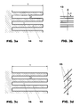
- Figure 3a shows in cross-section the parameters of the trip strips. Each trip strip has a height h measured from the wall 14 of the passage 5, and each trip strip 13 is arranged at a distance d from the adjacent trip strip. The height h and distance d are at a ratio of 10 ⁇ 2.
- the trip strips are shown having a rectangular shape. However, they can be of any other aerodynamically suitable cross-sectional shape as well.
- Figure 3b shows the orientation of the trip strips in relation to the direction of cooling air flow indicated by the angle ⁇ . The angle ⁇ is 90° ⁇ 10°.
- Figure 2 further shows the second cooling passage 6 having trip strips 15.
- the trip strips 15 in passage 6 are designed having a height h measured from the wall 16 of the passage 6 and distance d between them such that the ratio of height h to distance d is 10 ⁇ 2, as shown in figure 3c .
- Height h is measured from the wall of the passage, and distance d is measured between adjacent trip strips along the direction of cooling airflow.
- the trip strips 15 in cooling passage 6 as shown in figure 2 are at a greater distance from each other compared to the distance between adjacent trip strips 13 in passage 5.
- the essential design features of cooling passages in order to assure a sufficient cooling air flow through passages 5 and 6 are the specific angular orientation of the trip strips in passage 5 and the ratio of height h to distance d between adjacent trip strips of 10 ⁇ 2 for both passages 5 and 6.
- a further design feature, which enhances the cooling performance includes the specific angular orientation of the trip strips in passage 6.
- the trip strips are arranged at an angle ⁇ of 45 ⁇ 10° in relation to the direction of airflow, as shown in figure 3d .
- the third passage 7 can also comprise turbulators 17 of any design in order to enhance cooling efficiency along that passage.
- turbulators 17 are arranged at an inclination angle ⁇ to the direction of airflow, the angle being 45 ⁇ 10° in relation to the direction of airflow.
Landscapes
- Engineering & Computer Science (AREA)
- Mechanical Engineering (AREA)
- General Engineering & Computer Science (AREA)
- Turbine Rotor Nozzle Sealing (AREA)
Claims (2)
- Aube rotative (1) pour une turbine à gaz comprenant une base d'aube (2) et une pointe d'aube (3) et une structure de refroidissement interne, comprenant
un premier passage d'air de refroidissement (5) s'étendant essentiellement dans la direction longitudinale de l'aube depuis une chambre (4) dans la base d'aube (2) jusqu'à la pointe d'aube (3), un deuxième passage d'air de refroidissement (6) s'étendant depuis la pointe d'aube (3) jusqu'à la base d'aube (2) et un troisième passage d'air de refroidissement (7) s'étendant depuis la base d'aube (2) jusqu'à la pointe d'aube (3), le premier passage (5) étant en connexion fluidique avec le deuxième passage (6) au moyen d'un premier coude (9) et le deuxième passage (6) étant en connexion fluidique avec le troisième passage (7) au moyen d'un deuxième coude (10), et la structure de refroidissement comprenant en outre une ouverture (12) s'étendant depuis le deuxième coude (10) jusqu'à la chambre (4) en fournissant une sortie directe pour des fluides depuis l'aube,
et les premier et deuxième passages d'air de refroidissement (5, 6) comprenant chacun une pluralité de bandes de déclenchement (13, 15), les bandes de déclenchement (13) dans le premier passage de refroidissement (5) étant agencées suivant un angle (α) de 90 ± 10° par rapport à la direction de l'écoulement de fluide de refroidissement dans ce premier passage (5),
caractérisée en ce que
les bandes de déclenchement (15) dans le deuxième passage (6) sont arrangées suivant un angle (β) de 45° ± 10° par rapport à la direction de l'écoulement d'air,
et en outre, les bandes de déclenchement (13, 15) dans les premier et deuxième passages (5, 6) ont une hauteur (h) et une distance (d) entre les bandes de déclenchement adjacentes (13, 15), le rapport entre la hauteur (h) et la distance (d) étant de 10 ± 2. - Aube rotative (1) selon la revendication 1,
caractérisée en ce que
le troisième passage (7) comprend une pluralité de bandes de déclenchement (17) agencées suivant un angle (δ) de 45° ± 10°.
Priority Applications (8)
| Application Number | Priority Date | Filing Date | Title |
|---|---|---|---|
| DE602007011256T DE602007011256D1 (de) | 2007-08-08 | 2007-08-08 | Gasturbinenschaufel mit interner Kühlung |
| EP07113996A EP2025869B1 (fr) | 2007-08-08 | 2007-08-08 | Aube de turbine à gaz avec structure de refroidissement interne |
| AT07113996T ATE491863T1 (de) | 2007-08-08 | 2007-08-08 | Gasturbinenschaufel mit interner kühlung |
| SI200730541T SI2025869T1 (sl) | 2007-08-08 | 2007-08-08 | Lopatica plinske turbine z notranjim hlajenjem |
| US12/185,593 US20090041587A1 (en) | 2007-08-08 | 2008-08-04 | Turbine blade with internal cooling structure |
| MX2008010091A MX2008010091A (es) | 2007-08-08 | 2008-08-06 | Aspa de turbina con estructura de enfriamiento interna. |
| TW097129913A TWI374214B (en) | 2007-08-08 | 2008-08-06 | Turbine blade with internal cooling structure |
| CA2638535A CA2638535C (fr) | 2007-08-08 | 2008-08-07 | Aube de turbine avec structure de refroidissement interne |
Applications Claiming Priority (1)
| Application Number | Priority Date | Filing Date | Title |
|---|---|---|---|
| EP07113996A EP2025869B1 (fr) | 2007-08-08 | 2007-08-08 | Aube de turbine à gaz avec structure de refroidissement interne |
Publications (2)
| Publication Number | Publication Date |
|---|---|
| EP2025869A1 EP2025869A1 (fr) | 2009-02-18 |
| EP2025869B1 true EP2025869B1 (fr) | 2010-12-15 |
Family
ID=38805662
Family Applications (1)
| Application Number | Title | Priority Date | Filing Date |
|---|---|---|---|
| EP07113996A Active EP2025869B1 (fr) | 2007-08-08 | 2007-08-08 | Aube de turbine à gaz avec structure de refroidissement interne |
Country Status (8)
| Country | Link |
|---|---|
| US (1) | US20090041587A1 (fr) |
| EP (1) | EP2025869B1 (fr) |
| AT (1) | ATE491863T1 (fr) |
| CA (1) | CA2638535C (fr) |
| DE (1) | DE602007011256D1 (fr) |
| MX (1) | MX2008010091A (fr) |
| SI (1) | SI2025869T1 (fr) |
| TW (1) | TWI374214B (fr) |
Cited By (12)
| Publication number | Priority date | Publication date | Assignee | Title |
|---|---|---|---|---|
| US9579714B1 (en) | 2015-12-17 | 2017-02-28 | General Electric Company | Method and assembly for forming components having internal passages using a lattice structure |
| US9968991B2 (en) | 2015-12-17 | 2018-05-15 | General Electric Company | Method and assembly for forming components having internal passages using a lattice structure |
| US9987677B2 (en) | 2015-12-17 | 2018-06-05 | General Electric Company | Method and assembly for forming components having internal passages using a jacketed core |
| US10046389B2 (en) | 2015-12-17 | 2018-08-14 | General Electric Company | Method and assembly for forming components having internal passages using a jacketed core |
| US10099283B2 (en) | 2015-12-17 | 2018-10-16 | General Electric Company | Method and assembly for forming components having an internal passage defined therein |
| US10099284B2 (en) | 2015-12-17 | 2018-10-16 | General Electric Company | Method and assembly for forming components having a catalyzed internal passage defined therein |
| US10099276B2 (en) | 2015-12-17 | 2018-10-16 | General Electric Company | Method and assembly for forming components having an internal passage defined therein |
| US10118217B2 (en) | 2015-12-17 | 2018-11-06 | General Electric Company | Method and assembly for forming components having internal passages using a jacketed core |
| US10137499B2 (en) | 2015-12-17 | 2018-11-27 | General Electric Company | Method and assembly for forming components having an internal passage defined therein |
| US10150158B2 (en) | 2015-12-17 | 2018-12-11 | General Electric Company | Method and assembly for forming components having internal passages using a jacketed core |
| US10286450B2 (en) | 2016-04-27 | 2019-05-14 | General Electric Company | Method and assembly for forming components using a jacketed core |
| US10335853B2 (en) | 2016-04-27 | 2019-07-02 | General Electric Company | Method and assembly for forming components using a jacketed core |
Families Citing this family (10)
| Publication number | Priority date | Publication date | Assignee | Title |
|---|---|---|---|---|
| US11149548B2 (en) | 2013-11-13 | 2021-10-19 | Raytheon Technologies Corporation | Method of reducing manufacturing variation related to blocked cooling holes |
| WO2015073845A1 (fr) | 2013-11-15 | 2015-05-21 | United Technologies Corporation | Procédé et système d'usinage fluidique |
| US10156157B2 (en) * | 2015-02-13 | 2018-12-18 | United Technologies Corporation | S-shaped trip strips in internally cooled components |
| US10702958B2 (en) | 2017-02-22 | 2020-07-07 | General Electric Company | Method of manufacturing turbine airfoil and tip component thereof using ceramic core with witness feature |
| US11154956B2 (en) | 2017-02-22 | 2021-10-26 | General Electric Company | Method of repairing turbine component using ultra-thin plate |
| US10717130B2 (en) * | 2017-02-22 | 2020-07-21 | General Electric Company | Method of manufacturing turbine airfoil and tip component thereof |
| US10612394B2 (en) * | 2017-07-21 | 2020-04-07 | United Technologies Corporation | Airfoil having serpentine core resupply flow control |
| JP6996947B2 (ja) * | 2017-11-09 | 2022-01-17 | 三菱パワー株式会社 | タービン翼及びガスタービン |
| JP7096695B2 (ja) * | 2018-04-17 | 2022-07-06 | 三菱重工業株式会社 | タービン翼及びガスタービン |
| JP7847031B2 (ja) * | 2022-05-06 | 2026-04-16 | 三菱重工業株式会社 | タービン翼及びガスタービン |
Family Cites Families (13)
| Publication number | Priority date | Publication date | Assignee | Title |
|---|---|---|---|---|
| US4278400A (en) * | 1978-09-05 | 1981-07-14 | United Technologies Corporation | Coolable rotor blade |
| US4775296A (en) * | 1981-12-28 | 1988-10-04 | United Technologies Corporation | Coolable airfoil for a rotary machine |
| US5232343A (en) * | 1984-05-24 | 1993-08-03 | General Electric Company | Turbine blade |
| US5700132A (en) * | 1991-12-17 | 1997-12-23 | General Electric Company | Turbine blade having opposing wall turbulators |
| US5403159A (en) * | 1992-11-30 | 1995-04-04 | United Technoligies Corporation | Coolable airfoil structure |
| US6139269A (en) * | 1997-12-17 | 2000-10-31 | United Technologies Corporation | Turbine blade with multi-pass cooling and cooling air addition |
| JPH11241602A (ja) * | 1998-02-26 | 1999-09-07 | Toshiba Corp | ガスタービン翼 |
| EP0945595A3 (fr) * | 1998-03-26 | 2001-10-10 | Mitsubishi Heavy Industries, Ltd. | Aube refroidie pour turbine à gaz |
| EP1022435B1 (fr) * | 1999-01-25 | 2009-06-03 | General Electric Company | Circuit de refroidissement interne pour une aube de turbine à gaz |
| US6634858B2 (en) * | 2001-06-11 | 2003-10-21 | Alstom (Switzerland) Ltd | Gas turbine airfoil |
| US6884036B2 (en) * | 2003-04-15 | 2005-04-26 | General Electric Company | Complementary cooled turbine nozzle |
| US7097419B2 (en) * | 2004-07-26 | 2006-08-29 | General Electric Company | Common tip chamber blade |
| US7431561B2 (en) * | 2006-02-16 | 2008-10-07 | General Electric Company | Method and apparatus for cooling gas turbine rotor blades |
-
2007
- 2007-08-08 EP EP07113996A patent/EP2025869B1/fr active Active
- 2007-08-08 DE DE602007011256T patent/DE602007011256D1/de active Active
- 2007-08-08 AT AT07113996T patent/ATE491863T1/de not_active IP Right Cessation
- 2007-08-08 SI SI200730541T patent/SI2025869T1/sl unknown
-
2008
- 2008-08-04 US US12/185,593 patent/US20090041587A1/en not_active Abandoned
- 2008-08-06 MX MX2008010091A patent/MX2008010091A/es active IP Right Grant
- 2008-08-06 TW TW097129913A patent/TWI374214B/zh not_active IP Right Cessation
- 2008-08-07 CA CA2638535A patent/CA2638535C/fr active Active
Cited By (14)
| Publication number | Priority date | Publication date | Assignee | Title |
|---|---|---|---|---|
| US9579714B1 (en) | 2015-12-17 | 2017-02-28 | General Electric Company | Method and assembly for forming components having internal passages using a lattice structure |
| US9968991B2 (en) | 2015-12-17 | 2018-05-15 | General Electric Company | Method and assembly for forming components having internal passages using a lattice structure |
| US9975176B2 (en) | 2015-12-17 | 2018-05-22 | General Electric Company | Method and assembly for forming components having internal passages using a lattice structure |
| US9987677B2 (en) | 2015-12-17 | 2018-06-05 | General Electric Company | Method and assembly for forming components having internal passages using a jacketed core |
| US10046389B2 (en) | 2015-12-17 | 2018-08-14 | General Electric Company | Method and assembly for forming components having internal passages using a jacketed core |
| US10099283B2 (en) | 2015-12-17 | 2018-10-16 | General Electric Company | Method and assembly for forming components having an internal passage defined therein |
| US10099284B2 (en) | 2015-12-17 | 2018-10-16 | General Electric Company | Method and assembly for forming components having a catalyzed internal passage defined therein |
| US10099276B2 (en) | 2015-12-17 | 2018-10-16 | General Electric Company | Method and assembly for forming components having an internal passage defined therein |
| US10118217B2 (en) | 2015-12-17 | 2018-11-06 | General Electric Company | Method and assembly for forming components having internal passages using a jacketed core |
| US10137499B2 (en) | 2015-12-17 | 2018-11-27 | General Electric Company | Method and assembly for forming components having an internal passage defined therein |
| US10150158B2 (en) | 2015-12-17 | 2018-12-11 | General Electric Company | Method and assembly for forming components having internal passages using a jacketed core |
| US10286450B2 (en) | 2016-04-27 | 2019-05-14 | General Electric Company | Method and assembly for forming components using a jacketed core |
| US10335853B2 (en) | 2016-04-27 | 2019-07-02 | General Electric Company | Method and assembly for forming components using a jacketed core |
| US10981221B2 (en) | 2016-04-27 | 2021-04-20 | General Electric Company | Method and assembly for forming components using a jacketed core |
Also Published As
| Publication number | Publication date |
|---|---|
| CA2638535C (fr) | 2015-02-24 |
| MX2008010091A (es) | 2009-02-27 |
| TWI374214B (en) | 2012-10-11 |
| ATE491863T1 (de) | 2011-01-15 |
| EP2025869A1 (fr) | 2009-02-18 |
| DE602007011256D1 (de) | 2011-01-27 |
| US20090041587A1 (en) | 2009-02-12 |
| CA2638535A1 (fr) | 2009-02-08 |
| SI2025869T1 (sl) | 2011-04-29 |
| TW200928075A (en) | 2009-07-01 |
Similar Documents
| Publication | Publication Date | Title |
|---|---|---|
| EP2025869B1 (fr) | Aube de turbine à gaz avec structure de refroidissement interne | |
| US9797261B2 (en) | Internal cooling of engine components | |
| US7789626B1 (en) | Turbine blade with showerhead film cooling holes | |
| EP2565383B1 (fr) | Aube munie de canaux de refroidissement | |
| US8807943B1 (en) | Turbine blade with trailing edge cooling circuit | |
| EP2213838B1 (fr) | Procédé de coulage d'une aube de turbine | |
| US7217095B2 (en) | Heat transferring cooling features for an airfoil | |
| EP2912274B1 (fr) | Agencement de refroidissement pour élément de turbine à gaz | |
| EP2060745B1 (fr) | Segment d'étanchéité pour turbine à gaz | |
| EP2911815B1 (fr) | Noyau de coulée pour un arrangement de refroidissement pour un élément de turbine à gaz | |
| US8770936B1 (en) | Turbine blade with near wall cooling channels | |
| EP1561902B1 (fr) | Aube de turbine avec promoteurs de turbulence | |
| US20190316472A1 (en) | Double wall airfoil cooling configuration for gas turbine engine | |
| US7762775B1 (en) | Turbine airfoil with cooled thin trailing edge | |
| EP3399145B1 (fr) | Profil d'aube avec cavité hybride de bord d'attaque | |
| US7572102B1 (en) | Large tapered air cooled turbine blade | |
| EP3090145B1 (fr) | Turbulateur de passage de refroidissement de composant de turbine à gaz | |
| US5431537A (en) | Cooled gas turbine blade | |
| EP2103781A2 (fr) | Microcircuit de refroidissement de bord arrière avec des sorties alternées convergentes | |
| EP2211019A2 (fr) | Aube de rotor | |
| EP3246110B1 (fr) | Noyau en métal réfractaire et son procédé de fabrication | |
| EP3425165B1 (fr) | Composant mécanique | |
| US9109451B1 (en) | Turbine blade with micro sized near wall cooling channels | |
| US6824352B1 (en) | Vane enhanced trailing edge cooling design | |
| US11719102B2 (en) | Blade provided with a cooling circuit |
Legal Events
| Date | Code | Title | Description |
|---|---|---|---|
| PUAI | Public reference made under article 153(3) epc to a published international application that has entered the european phase |
Free format text: ORIGINAL CODE: 0009012 |
|
| AK | Designated contracting states |
Kind code of ref document: A1 Designated state(s): AT BE BG CH CY CZ DE DK EE ES FI FR GB GR HU IE IS IT LI LT LU LV MC MT NL PL PT RO SE SI SK TR |
|
| AX | Request for extension of the european patent |
Extension state: AL BA HR MK RS |
|
| 17P | Request for examination filed |
Effective date: 20090817 |
|
| AKX | Designation fees paid |
Designated state(s): AT BE BG CH CY CZ DE DK EE ES FI FR GB GR HU IE IS IT LI LT LU LV MC MT NL PL PT RO SE SI SK TR |
|
| 17Q | First examination report despatched |
Effective date: 20091223 |
|
| GRAP | Despatch of communication of intention to grant a patent |
Free format text: ORIGINAL CODE: EPIDOSNIGR1 |
|
| GRAS | Grant fee paid |
Free format text: ORIGINAL CODE: EPIDOSNIGR3 |
|
| GRAA | (expected) grant |
Free format text: ORIGINAL CODE: 0009210 |
|
| AK | Designated contracting states |
Kind code of ref document: B1 Designated state(s): AT BE BG CH CY CZ DE DK EE ES FI FR GB GR HU IE IS IT LI LT LU LV MC MT NL PL PT RO SE SI SK TR |
|
| REG | Reference to a national code |
Ref country code: GB Ref legal event code: FG4D Ref country code: CH Ref legal event code: EP |
|
| REG | Reference to a national code |
Ref country code: IE Ref legal event code: FG4D |
|
| REF | Corresponds to: |
Ref document number: 602007011256 Country of ref document: DE Date of ref document: 20110127 Kind code of ref document: P |
|
| REG | Reference to a national code |
Ref country code: NL Ref legal event code: T3 |
|
| PG25 | Lapsed in a contracting state [announced via postgrant information from national office to epo] |
Ref country code: LT Free format text: LAPSE BECAUSE OF FAILURE TO SUBMIT A TRANSLATION OF THE DESCRIPTION OR TO PAY THE FEE WITHIN THE PRESCRIBED TIME-LIMIT Effective date: 20101215 |
|
| LTIE | Lt: invalidation of european patent or patent extension |
Effective date: 20101215 |
|
| PG25 | Lapsed in a contracting state [announced via postgrant information from national office to epo] |
Ref country code: BG Free format text: LAPSE BECAUSE OF FAILURE TO SUBMIT A TRANSLATION OF THE DESCRIPTION OR TO PAY THE FEE WITHIN THE PRESCRIBED TIME-LIMIT Effective date: 20110315 Ref country code: LV Free format text: LAPSE BECAUSE OF FAILURE TO SUBMIT A TRANSLATION OF THE DESCRIPTION OR TO PAY THE FEE WITHIN THE PRESCRIBED TIME-LIMIT Effective date: 20101215 Ref country code: CY Free format text: LAPSE BECAUSE OF FAILURE TO SUBMIT A TRANSLATION OF THE DESCRIPTION OR TO PAY THE FEE WITHIN THE PRESCRIBED TIME-LIMIT Effective date: 20101215 Ref country code: AT Free format text: LAPSE BECAUSE OF FAILURE TO SUBMIT A TRANSLATION OF THE DESCRIPTION OR TO PAY THE FEE WITHIN THE PRESCRIBED TIME-LIMIT Effective date: 20101215 Ref country code: SE Free format text: LAPSE BECAUSE OF FAILURE TO SUBMIT A TRANSLATION OF THE DESCRIPTION OR TO PAY THE FEE WITHIN THE PRESCRIBED TIME-LIMIT Effective date: 20101215 Ref country code: FI Free format text: LAPSE BECAUSE OF FAILURE TO SUBMIT A TRANSLATION OF THE DESCRIPTION OR TO PAY THE FEE WITHIN THE PRESCRIBED TIME-LIMIT Effective date: 20101215 |
|
| PG25 | Lapsed in a contracting state [announced via postgrant information from national office to epo] |
Ref country code: BE Free format text: LAPSE BECAUSE OF FAILURE TO SUBMIT A TRANSLATION OF THE DESCRIPTION OR TO PAY THE FEE WITHIN THE PRESCRIBED TIME-LIMIT Effective date: 20101215 Ref country code: EE Free format text: LAPSE BECAUSE OF FAILURE TO SUBMIT A TRANSLATION OF THE DESCRIPTION OR TO PAY THE FEE WITHIN THE PRESCRIBED TIME-LIMIT Effective date: 20101215 Ref country code: GR Free format text: LAPSE BECAUSE OF FAILURE TO SUBMIT A TRANSLATION OF THE DESCRIPTION OR TO PAY THE FEE WITHIN THE PRESCRIBED TIME-LIMIT Effective date: 20110316 Ref country code: CZ Free format text: LAPSE BECAUSE OF FAILURE TO SUBMIT A TRANSLATION OF THE DESCRIPTION OR TO PAY THE FEE WITHIN THE PRESCRIBED TIME-LIMIT Effective date: 20101215 Ref country code: PT Free format text: LAPSE BECAUSE OF FAILURE TO SUBMIT A TRANSLATION OF THE DESCRIPTION OR TO PAY THE FEE WITHIN THE PRESCRIBED TIME-LIMIT Effective date: 20110415 Ref country code: IS Free format text: LAPSE BECAUSE OF FAILURE TO SUBMIT A TRANSLATION OF THE DESCRIPTION OR TO PAY THE FEE WITHIN THE PRESCRIBED TIME-LIMIT Effective date: 20110415 Ref country code: ES Free format text: LAPSE BECAUSE OF FAILURE TO SUBMIT A TRANSLATION OF THE DESCRIPTION OR TO PAY THE FEE WITHIN THE PRESCRIBED TIME-LIMIT Effective date: 20110326 |
|
| PG25 | Lapsed in a contracting state [announced via postgrant information from national office to epo] |
Ref country code: PL Free format text: LAPSE BECAUSE OF FAILURE TO SUBMIT A TRANSLATION OF THE DESCRIPTION OR TO PAY THE FEE WITHIN THE PRESCRIBED TIME-LIMIT Effective date: 20101215 Ref country code: SK Free format text: LAPSE BECAUSE OF FAILURE TO SUBMIT A TRANSLATION OF THE DESCRIPTION OR TO PAY THE FEE WITHIN THE PRESCRIBED TIME-LIMIT Effective date: 20101215 Ref country code: RO Free format text: LAPSE BECAUSE OF FAILURE TO SUBMIT A TRANSLATION OF THE DESCRIPTION OR TO PAY THE FEE WITHIN THE PRESCRIBED TIME-LIMIT Effective date: 20101215 |
|
| PLBE | No opposition filed within time limit |
Free format text: ORIGINAL CODE: 0009261 |
|
| STAA | Information on the status of an ep patent application or granted ep patent |
Free format text: STATUS: NO OPPOSITION FILED WITHIN TIME LIMIT |
|
| PG25 | Lapsed in a contracting state [announced via postgrant information from national office to epo] |
Ref country code: DK Free format text: LAPSE BECAUSE OF FAILURE TO SUBMIT A TRANSLATION OF THE DESCRIPTION OR TO PAY THE FEE WITHIN THE PRESCRIBED TIME-LIMIT Effective date: 20101215 |
|
| 26N | No opposition filed |
Effective date: 20110916 |
|
| PG25 | Lapsed in a contracting state [announced via postgrant information from national office to epo] |
Ref country code: MT Free format text: LAPSE BECAUSE OF FAILURE TO SUBMIT A TRANSLATION OF THE DESCRIPTION OR TO PAY THE FEE WITHIN THE PRESCRIBED TIME-LIMIT Effective date: 20101215 Ref country code: IT Free format text: LAPSE BECAUSE OF FAILURE TO SUBMIT A TRANSLATION OF THE DESCRIPTION OR TO PAY THE FEE WITHIN THE PRESCRIBED TIME-LIMIT Effective date: 20101215 |
|
| REG | Reference to a national code |
Ref country code: DE Ref legal event code: R097 Ref document number: 602007011256 Country of ref document: DE Effective date: 20110916 |
|
| PG25 | Lapsed in a contracting state [announced via postgrant information from national office to epo] |
Ref country code: MC Free format text: LAPSE BECAUSE OF NON-PAYMENT OF DUE FEES Effective date: 20110831 |
|
| REG | Reference to a national code |
Ref country code: FR Ref legal event code: ST Effective date: 20120430 |
|
| REG | Reference to a national code |
Ref country code: IE Ref legal event code: MM4A |
|
| PG25 | Lapsed in a contracting state [announced via postgrant information from national office to epo] |
Ref country code: IE Free format text: LAPSE BECAUSE OF NON-PAYMENT OF DUE FEES Effective date: 20110808 |
|
| PG25 | Lapsed in a contracting state [announced via postgrant information from national office to epo] |
Ref country code: FR Free format text: LAPSE BECAUSE OF NON-PAYMENT OF DUE FEES Effective date: 20110831 |
|
| PG25 | Lapsed in a contracting state [announced via postgrant information from national office to epo] |
Ref country code: LU Free format text: LAPSE BECAUSE OF NON-PAYMENT OF DUE FEES Effective date: 20110808 |
|
| PG25 | Lapsed in a contracting state [announced via postgrant information from national office to epo] |
Ref country code: TR Free format text: LAPSE BECAUSE OF FAILURE TO SUBMIT A TRANSLATION OF THE DESCRIPTION OR TO PAY THE FEE WITHIN THE PRESCRIBED TIME-LIMIT Effective date: 20101215 |
|
| PG25 | Lapsed in a contracting state [announced via postgrant information from national office to epo] |
Ref country code: HU Free format text: LAPSE BECAUSE OF FAILURE TO SUBMIT A TRANSLATION OF THE DESCRIPTION OR TO PAY THE FEE WITHIN THE PRESCRIBED TIME-LIMIT Effective date: 20101215 |
|
| REG | Reference to a national code |
Ref country code: CH Ref legal event code: PFA Owner name: GENERAL ELECTRIC TECHNOLOGY GMBH, CH Free format text: FORMER OWNER: ALSTOM TECHNOLOGY LTD, CH |
|
| REG | Reference to a national code |
Ref country code: NL Ref legal event code: HC Owner name: GENERAL ELECTRIC TECHNOLOGY GMBH; CH Free format text: DETAILS ASSIGNMENT: VERANDERING VAN EIGENAAR(S), VERANDERING VAN NAAM VAN DE EIGENAAR(S); FORMER OWNER NAME: ALSTOM TECHNOLOGY LTD Effective date: 20160623 |
|
| REG | Reference to a national code |
Ref country code: DE Ref legal event code: R082 Ref document number: 602007011256 Country of ref document: DE Representative=s name: RUEGER | ABEL PATENT- UND RECHTSANWAELTE, DE Ref country code: DE Ref legal event code: R082 Ref document number: 602007011256 Country of ref document: DE Representative=s name: RUEGER ABEL PATENTANWAELTE PARTGMBB, DE Ref country code: DE Ref legal event code: R082 Ref document number: 602007011256 Country of ref document: DE Representative=s name: RUEGER, BARTHELT & ABEL, DE Ref country code: DE Ref legal event code: R081 Ref document number: 602007011256 Country of ref document: DE Owner name: GENERAL ELECTRIC TECHNOLOGY GMBH, CH Free format text: FORMER OWNER: ALSTOM TECHNOLOGY LTD., BADEN, CH Ref country code: DE Ref legal event code: R082 Ref document number: 602007011256 Country of ref document: DE Representative=s name: RUEGER ABEL PATENT- UND RECHTSANWAELTE, DE |
|
| REG | Reference to a national code |
Ref country code: SI Ref legal event code: SP73 Owner name: GENERAL ELECTRIC TECHNOLOGY GMBH; CH Effective date: 20160905 |
|
| PGFP | Annual fee paid to national office [announced via postgrant information from national office to epo] |
Ref country code: IS Payment date: 20170515 Year of fee payment: 13 |
|
| REG | Reference to a national code |
Ref country code: CH Ref legal event code: PL |
|
| PG25 | Lapsed in a contracting state [announced via postgrant information from national office to epo] |
Ref country code: CH Free format text: LAPSE BECAUSE OF NON-PAYMENT OF DUE FEES Effective date: 20180831 Ref country code: LI Free format text: LAPSE BECAUSE OF NON-PAYMENT OF DUE FEES Effective date: 20180831 |
|
| PGFP | Annual fee paid to national office [announced via postgrant information from national office to epo] |
Ref country code: SI Payment date: 20190722 Year of fee payment: 13 |
|
| PG25 | Lapsed in a contracting state [announced via postgrant information from national office to epo] |
Ref country code: SI Free format text: LAPSE BECAUSE OF NON-PAYMENT OF DUE FEES Effective date: 20200809 |
|
| PGFP | Annual fee paid to national office [announced via postgrant information from national office to epo] |
Ref country code: NL Payment date: 20250723 Year of fee payment: 19 |
|
| PGFP | Annual fee paid to national office [announced via postgrant information from national office to epo] |
Ref country code: DE Payment date: 20250724 Year of fee payment: 19 |
|
| PGFP | Annual fee paid to national office [announced via postgrant information from national office to epo] |
Ref country code: GB Payment date: 20250724 Year of fee payment: 19 |