EP2026101A2 - Dispositif de mesure de portée - Google Patents
Dispositif de mesure de portée Download PDFInfo
- Publication number
- EP2026101A2 EP2026101A2 EP08162045A EP08162045A EP2026101A2 EP 2026101 A2 EP2026101 A2 EP 2026101A2 EP 08162045 A EP08162045 A EP 08162045A EP 08162045 A EP08162045 A EP 08162045A EP 2026101 A2 EP2026101 A2 EP 2026101A2
- Authority
- EP
- European Patent Office
- Prior art keywords
- measurement device
- range measurement
- objects
- range
- laser pulse
- Prior art date
- Legal status (The legal status is an assumption and is not a legal conclusion. Google has not performed a legal analysis and makes no representation as to the accuracy of the status listed.)
- Withdrawn
Links
Images



Classifications
-
- G—PHYSICS
- G01—MEASURING; TESTING
- G01S—RADIO DIRECTION-FINDING; RADIO NAVIGATION; DETERMINING DISTANCE OR VELOCITY BY USE OF RADIO WAVES; LOCATING OR PRESENCE-DETECTING BY USE OF THE REFLECTION OR RERADIATION OF RADIO WAVES; ANALOGOUS ARRANGEMENTS USING OTHER WAVES
- G01S17/00—Systems using the reflection or reradiation of electromagnetic waves other than radio waves, e.g. lidar systems
- G01S17/86—Combinations of lidar systems with systems other than lidar, radar or sonar, e.g. with direction finders
-
- G—PHYSICS
- G01—MEASURING; TESTING
- G01S—RADIO DIRECTION-FINDING; RADIO NAVIGATION; DETERMINING DISTANCE OR VELOCITY BY USE OF RADIO WAVES; LOCATING OR PRESENCE-DETECTING BY USE OF THE REFLECTION OR RERADIATION OF RADIO WAVES; ANALOGOUS ARRANGEMENTS USING OTHER WAVES
- G01S17/00—Systems using the reflection or reradiation of electromagnetic waves other than radio waves, e.g. lidar systems
- G01S17/02—Systems using the reflection of electromagnetic waves other than radio waves
- G01S17/06—Systems determining position data of a target
- G01S17/08—Systems determining position data of a target for measuring distance only
- G01S17/10—Systems determining position data of a target for measuring distance only using transmission of interrupted, pulse-modulated waves
-
- G—PHYSICS
- G01—MEASURING; TESTING
- G01S—RADIO DIRECTION-FINDING; RADIO NAVIGATION; DETERMINING DISTANCE OR VELOCITY BY USE OF RADIO WAVES; LOCATING OR PRESENCE-DETECTING BY USE OF THE REFLECTION OR RERADIATION OF RADIO WAVES; ANALOGOUS ARRANGEMENTS USING OTHER WAVES
- G01S17/00—Systems using the reflection or reradiation of electromagnetic waves other than radio waves, e.g. lidar systems
- G01S17/02—Systems using the reflection of electromagnetic waves other than radio waves
- G01S17/06—Systems determining position data of a target
- G01S17/42—Simultaneous measurement of distance and other co-ordinates
-
- G—PHYSICS
- G01—MEASURING; TESTING
- G01S—RADIO DIRECTION-FINDING; RADIO NAVIGATION; DETERMINING DISTANCE OR VELOCITY BY USE OF RADIO WAVES; LOCATING OR PRESENCE-DETECTING BY USE OF THE REFLECTION OR RERADIATION OF RADIO WAVES; ANALOGOUS ARRANGEMENTS USING OTHER WAVES
- G01S17/00—Systems using the reflection or reradiation of electromagnetic waves other than radio waves, e.g. lidar systems
- G01S17/66—Tracking systems using electromagnetic waves other than radio waves
-
- G—PHYSICS
- G01—MEASURING; TESTING
- G01S—RADIO DIRECTION-FINDING; RADIO NAVIGATION; DETERMINING DISTANCE OR VELOCITY BY USE OF RADIO WAVES; LOCATING OR PRESENCE-DETECTING BY USE OF THE REFLECTION OR RERADIATION OF RADIO WAVES; ANALOGOUS ARRANGEMENTS USING OTHER WAVES
- G01S17/00—Systems using the reflection or reradiation of electromagnetic waves other than radio waves, e.g. lidar systems
- G01S17/87—Combinations of systems using electromagnetic waves other than radio waves
-
- G—PHYSICS
- G01—MEASURING; TESTING
- G01S—RADIO DIRECTION-FINDING; RADIO NAVIGATION; DETERMINING DISTANCE OR VELOCITY BY USE OF RADIO WAVES; LOCATING OR PRESENCE-DETECTING BY USE OF THE REFLECTION OR RERADIATION OF RADIO WAVES; ANALOGOUS ARRANGEMENTS USING OTHER WAVES
- G01S17/00—Systems using the reflection or reradiation of electromagnetic waves other than radio waves, e.g. lidar systems
- G01S17/88—Lidar systems specially adapted for specific applications
- G01S17/89—Lidar systems specially adapted for specific applications for mapping or imaging
- G01S17/894—Three-dimensional [3D] imaging with simultaneous measurement of time-of-flight at a two-dimensional [2D] array of receiver pixels, e.g. time-of-flight cameras or flash lidar
-
- G—PHYSICS
- G01—MEASURING; TESTING
- G01S—RADIO DIRECTION-FINDING; RADIO NAVIGATION; DETERMINING DISTANCE OR VELOCITY BY USE OF RADIO WAVES; LOCATING OR PRESENCE-DETECTING BY USE OF THE REFLECTION OR RERADIATION OF RADIO WAVES; ANALOGOUS ARRANGEMENTS USING OTHER WAVES
- G01S7/00—Details of systems according to groups G01S13/00, G01S15/00, G01S17/00
- G01S7/48—Details of systems according to groups G01S13/00, G01S15/00, G01S17/00 of systems according to group G01S17/00
- G01S7/481—Constructional features, e.g. arrangements of optical elements
- G01S7/4814—Constructional features, e.g. arrangements of optical elements of transmitters alone
-
- G—PHYSICS
- G01—MEASURING; TESTING
- G01S—RADIO DIRECTION-FINDING; RADIO NAVIGATION; DETERMINING DISTANCE OR VELOCITY BY USE OF RADIO WAVES; LOCATING OR PRESENCE-DETECTING BY USE OF THE REFLECTION OR RERADIATION OF RADIO WAVES; ANALOGOUS ARRANGEMENTS USING OTHER WAVES
- G01S7/00—Details of systems according to groups G01S13/00, G01S15/00, G01S17/00
- G01S7/48—Details of systems according to groups G01S13/00, G01S15/00, G01S17/00 of systems according to group G01S17/00
- G01S7/481—Constructional features, e.g. arrangements of optical elements
- G01S7/4816—Constructional features, e.g. arrangements of optical elements of receivers alone
-
- G—PHYSICS
- G01—MEASURING; TESTING
- G01S—RADIO DIRECTION-FINDING; RADIO NAVIGATION; DETERMINING DISTANCE OR VELOCITY BY USE OF RADIO WAVES; LOCATING OR PRESENCE-DETECTING BY USE OF THE REFLECTION OR RERADIATION OF RADIO WAVES; ANALOGOUS ARRANGEMENTS USING OTHER WAVES
- G01S7/00—Details of systems according to groups G01S13/00, G01S15/00, G01S17/00
- G01S7/48—Details of systems according to groups G01S13/00, G01S15/00, G01S17/00 of systems according to group G01S17/00
- G01S7/4808—Evaluating distance, position or velocity data
Definitions
- GPS global positioning system
- GPS has some limitations.
- the GPS signals may not be available in a desired location where satellite communication is blocked or scrambled.
- the GPS sensors do not obtain any local features of the area (for example, any additional surrounding objects or landmarks within the area) relative to the location of the vehicle. To date, tracking any localized features requires additional synchronization time in instances where accurate measurements within a minimal time period are critical.
- a range measurement device comprising a flash laser radar configured to produce a first laser pulse at a first time.
- the device receives, at a second time, reflections of the first laser pulse from at least one object within a 360 degree field of view.
- the device further comprises a timing electronics module, an image sensor in communication with the timing electronics module, a mirror element coupled between the image sensor and the laser radar, and a lens.
- the mirror element includes a first reflector configured to disperse the reflections of the first laser pulse within at least a portion of the 360 degree field of view and a second reflector configured to collect returning reflections of the first laser pulse from the at least one object into the image sensor.
- the lens is configured to focus the returning reflections onto the image sensor.
- Embodiments of the present invention relate to a range measurement device that determines an absolute location and attitude of the system with respect to local objects with absolute known locations (referred to herein as targeted objects) and, in at least one alternate application, a relative location and attitude of the system with respect to any local objects within range of the range measurement device (referred to herein as surrounding objects).
- the range measurement device discussed herein determines the location of the system using a pulse from a laser radar (LADAR).
- LADAR laser radar
- the range measurement device provides synchronized measurements of the surrounding objects within a 360° field of view along the horizon and returns the distance and angular relationship between the range measurement device and the surrounding objects.
- the range measurement device mounts on an unmanned ground vehicle (UGV) interested in at least one of recording an absolute location of the UGV, tracking another vehicle or object within the localized area, and determining a relative location and attitude of the UGV within the localized area.
- UGV unmanned ground vehicle
- the use of a LADAR improves range tracking accuracy.
- the range measurement device discussed here measures an accurate range as well as the angular relationship of the surrounding objects relative to the range measurement device.
- range, location, and azimuth measurements of the surrounding objects are synchronously measured to a plurality of three-dimensional (3-D) images using the LADAR output.
- the accurate range measurements are used to locate the device either absolutely or relatively (which is useful in 3-D rendering and mapping applications and allows for localization and mapping in a single process).
- the LADAR produces a laser pulse and a charge-coupled device (CCD) sensitive to the laser pulse receives at least one reflection from the surrounding objects "of interest.” Based on the reflection(s) received, the CCD can measure a flight time of the laser pulse.
- measurements from the CCD are used by a processor in the range measurement device to determine the location of the UGV relative to any of the surrounding objects identified.
- location coordinates for example, latitude, longitude, and altitude
- the 3-D information can be used to determine the attitude of the object (for example, heading pitch and roll).
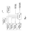
- FIG. 1 is a block diagram of a navigation system 100.
- the navigation system 100 includes a processor 102 that is in communication with a range measurement device 106 (which, in this embodiment, comprises a 360° 3-D flash LADAR).
- the system 100 includes at least one additional sensor such as a GPS sensor 108, an inertial sensor 110, a heading sensor 112, a speed sensor 114, and an altimeter sensor 116.
- the range measurement device 106 provides range data, including distances and angles, to the processor 102 of objects near a host vehicle having the system 100. Many methods of communication are possible including CCD pixel information, however, one skilled in the art can determine methods for providing distance and angle information.
- a 360° 3-D flash LADAR is used in the range measurement device 106.
- the LADAR-based range measurement device 106 detects and locates the objects using a single flash of laser light and provides information similar to radar.
- the range measurement device 106 illuminates a 360° field of view so that objects in any direction along the horizon from the range measurement device 106 are located (for example, located as the host vehicle traverses throughout an area, similar to the area discussed below with respect to FIG. 2 ).
- the range measurement device 106 tracks individual angles and ranges between the objects and the range measurement device 106 (for example, relative distance data).
- the relative distance data can be transformed to Earth-referenced angles for the objects in a specified area (for example, relative distance data). Both the relative and absolute distance data are processed in the processor 102.
- additional information is provided to the processor 102 to estimate the location of the host vehicle.
- the inertial sensor 110 estimates a present position based on a prior knowledge of time, initial position, initial velocity, initial orientation without the aid of external information.
- an initial position input and an initial heading input is provided.
- the information generated by the inertial sensor 110 (in this embodiment) is provided to the processor 102.
- the processor 102 uses the inertial sensor 110 data, in combination with the distance and angle data, from the ranging device 106 to determine the current location of the host vehicle.
- the current location and current heading is output as illustrated in FIG. 1 .
- the output of the current heading and current location is used to position the system 100 with both absolute and relative navigation coordinates.
- FIG. 2 is a traverse diagram 200 illustrating a host vehicle 207 (for example, a UGV) passing through an area 200 to be traversed.
- the area 200 to be traversed includes objects 210 1 through 210 N .
- the objects 210 1 through 210 N are mapped (for example, previously located) according to a correlation position determination method as disclosed in the '313 Application. In alternate implementations, locations of the objects 210 1 through 210 N are not previously known.
- the host vehicle 207 takes a path 206 that starts at a first point 202 and ends at a second point 204.
- the host vehicle 207 comprises a navigation system 208 including the range measurement device 106 of FIG. 1 . In the example embodiment of FIG.
- the range measurement device 106 of the navigation system 208 transmits (for example, flashes a laser light pulse from a flash LADAR) and receives a 3-D image of the objects 210 through the use of a mirror element and an image sensor, as further described below with respect to FIG. 3 .
- FIG. 3 is a block diagram of a range measurement device 300.
- the device 300 represents the range measurement device 106 of FIG. 1 .
- the device 300 in this embodiment comprises a flash laser radar (LADAR) 302, a mirror element 304 (comprising a first reflector 314 and a second reflector 316), and a timing electronics module 306 in communication with the image sensor 310 and a lens 308.
- LADAR flash laser radar
- the timing electronics module 306 monitors sensitivity of the image sensor 310 by controlling a shutter of the lens 308 with a "Shutter Control Signal" communication link.
- the timing electronics module 306 controls the initiation of a first laser pulse originating from the flash LADAR 302 to illuminate a target (for example, the objects 210 of FIG. 2 ) with a "Flash Control Signal” communication link.
- the timing electronics modules 306 further comprises one or more timers 312 operable to measure signal transit timing of the first laser pulse with a "Timing Control Signal” communication link as shown in FIG. 3 .
- the image sensor 310 is a charge-coupled device (CCD).
- the image sensor 310 consists of an integrated circuit containing an array of linked, or coupled, light-sensitive capacitors (that is, pixels).
- the mirror element 304 is a 3-D reflective surface.
- the first reflector 314 is one of a cone, a trapezoid, a sphere, or any other surface which can disperse the first laser pulse into the required field
- the second reflector 316 is one of a cone, a trapezoid, a sphere, or any other surface which can focus a first reflected laser pulse into the lens 308, as further discussed below.
- the image sensor 310 contains at least one pixel grid array to sense the returned 3-D reflections from the mirror element 304. As discussed in further detail below, the image sensor 310 further provides the intensity of the reflection to the processor 102 and terminates the signal transit timing in the timing electronics module 306.
- the flash LADAR 302 illuminates the objects 210 surrounding the device 300 in a 360° radius through a reflective surface (for example, the mirror element 304).
- the first reflector 314 is configured to disperse reflections of a first laser pulse into a 360° field of view.
- the second reflector 316 collects returning laser pulse reflections of the first laser pulse onto the lens 308.
- at least a portion of the field of view less than 360° can be selected.
- the first laser pulse from the flash LADAR 302 reflects in all directions (that is, the first laser pulse reflects 360°) from the first reflector 314 and returns the reflections back from the objects 210 to the second reflector 316.
- the lens 308 focuses the return reflections from the second reflector 316 on a focal plane of the image sensor 310. From the return reflection(s) of the second reflector 316, the lens 308 captures an image of at least one of the objects 210 for the image sensor 310. In the example embodiment of FIG. 3 , the focused reflection captured by the lens 308 causes each capacitor in the pixel array of the image sensor 310 to accumulate an electric charge proportional to the light intensity at the location of each of the objects 210.
- relative angular measurements of each of the objects 210 are taken by the processor 102.
- a local distance between the flash LADAR 302 and the surrounding objects 210 is also determined given a propagation time of the flash LADAR 302 from flash to reception taken at each pixel of the image sensor 310.
- a relative range for each of the objects 210 is computed given the local distance and a relative velocity (for example, the speed of light) of the first laser pulse return reflections. The relative range is calculated based on the length of time it takes for the light (for example, the first laser pulse) to return from the target.
- a 3-D image is created.
- independent pixels within the image sensor 310 stop the timers 312 of the timing electronics module 306.
- the image sensor 310 measures the change in light intensity to stop the signal transit timing (initiated at the time the "Flash Control Signal" is sent from the timing electronics module 306 to the flash LADAR 302) to determine the relative range to each of the objects 210 for each illuminated pixel in the image sensor 310.
- the propagation time between initializing the first laser pulse and the received reflection image is proportional to the range from the range measurement device 300 to the objects 210 based on the relative velocity of the first laser pulse return reflections.
- range, location, and azimuth measurements of the objects 210 are synchronized to each 3-D image produced.
- the host vehicle 207 (of FIG. 2 ) is localized with as few as two measurements. Moreover, the laser pulses available with the flash LADAR 302 increase the measurement accuracy of the range measurement device 300. In one implementation, any potential objects of interest are localized relative to the host vehicle 207 with the range measurement device 300 as discussed below.
- accurately measured ranges are used to locate the host vehicle 207 to at least four objects 210 previously surveyed.
- each pixel on the image sensor 310 records range to whatever illuminated that pixel.
- only pixels with very strong returns are considered since those pixels will correspond to reflective surveyed markers present on the at least four surveyed objects 210. It is understood that many means exist for identifying the targeted objects 210 that are well known in the art.
- a first pixel coordinate (i, j) in (for example) a 128 x 128 pixel layer CCD in the image sensor 310 provides an estimate of a unit-vector towards at least one of the objects 210 that illuminated the first pixel at (i, j). Together, the range and unit vector provide a first estimate of the targeted object 210's location in polar coordinates. Additionally, this first estimate identifies which of the at least four (surveyed) objects 210 is illuminating the first pixel. In the example embodiment of FIG.
- Equation 1 Given the surveyed ranges of the targeted objects 210, an accurate estimate of the location of the host vehicle 207 is determined with Equations 1 to 6 described below, where subtracting two range equations (for example, Equations 1 and 2) eliminates the unknown quadratic terms and results in a linear equation (for example, Equation 3).
- Equations 1 and 2 illustrated below use Cartesian grid coordinates ( x 1 , y 1 , z 1 ) and ( x 2 , y 2 , z 2 ) for the location of the objects 210 1 and 210 2 at two known locations, and a first unknown position ( x 0 , y 0 , z 0 ), with measured ranges of r 1 and r 2 from the range measurement device 300 to the objects 210 1 and 210 2 .
- Equation 1 - Equation 2 0
- Equation 1 - Equation 2 0
- Equation 3 is a linear equation with unknowns ( x 0 , y 0 , z 0 ).
- the at least four surveyed markers result in at least six linear equations from the six combinations (for example, (1-2), (1-3), (1-4), (2-3), (2-4) and (3-4)) as shown below:
- Equation 5 The above example provides at least 6 linear equations with at least 3 unknowns ( x 0 , y 0 , z 0 ), which are solved using commonly-known linear algebra and a least squares solution. These equations are written in vector notation as illustrated below in Equation 5, with a least squares solution to [ x ⁇ ] shown below in Equation 6.
- Equation 6 is a location of the host vehicle 207, [ x ⁇ ], localized to the targeted objects 210 using the range data of the flash LADAR 302.
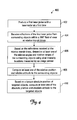
- FIG. 4 is a flow diagram of a method 400 for measuring range to determine a laser radar position.
- the method 400 uses a range measurement device similar to the range measurement device 300 of FIG. 3 to perform 360° range tracking of an area surrounding a vehicle (for example, the host vehicle 207 of FIG. 2 ).
- the method discussed here returns the distance and angular relationship between the vehicle and any surrounding objects currently positioned in the area.
- the range measurement device 300 includes a flash, a mirror element, and a CCD-based image sensor so that the surrounding objects can be detected in a 360° field of view.
- the range measurement device produces a first laser pulse with the laser radar at a first time dispersed over the 360° field of view.
- a timing electronics module of the range measurement device controls the initiation of the first laser pulse in order to properly illuminate at least one surrounding object.
- the range measurement device receives reflections of the first laser pulse reflected from surrounding objects within the 360 degree field of view at a second time (block 404).
- the second time comprises a relative transit time of the reflected first laser pulse within a localized time period between the first and second times.
- the range measurement device tracks at least one of a range and an attitude from the vehicle to the at least one surrounding object (block 406).
- signal transit times between producing the flash pulse to reception at the CCD-based image sensor and pixel intensity locations measured by the CCD-based image sensor are used to determine the relative angles and relative ranges of the surrounding objects.
- the range measurement device determines additional localized time periods to determine at least one of a current position and a current attitude of the host vehicle relative to the surrounding objects (block 408).
- computing performed at block 408 comprises measuring the additional localized time periods to determine a current heading, pitch, and roll of the vehicle.
- the range measurement device determines an absolute position of the vehicle, records at least one relative position angle between the target and the vehicle, and computes at least one of an absolute position and absolute attitude to the targeted objects (block 410).
- FIG. 5 is a flow diagram of a method 500 for measuring range to determine target positions.
- the method 500 addresses using a first laser pulse from the range measurement device 300 of FIG. 3 to perform 360° range tracking of an area surrounding a vehicle (for example, the host vehicle 207 of FIG. 2 ) and returns the distance and angular relationship between the vehicle and any (known) targeted objects currently positioned in the area.
- the range measurement device used for the method of FIG. 5 includes a flash, a mirror element, and a CCD-based image sensor for the targeted objects of the objects 210 to be detected in a 360° field of view.
- the range measurement device produces a first laser pulse with the laser radar at a first time dispersed over the 360° field of view.
- a timing electronics module of the range measurement device controls the initiation of the first laser pulse in order to properly illuminate at least one surrounding object.
- the range measurement device receives reflections of the first laser pulse from surrounding objects within the 360 degree field of view at a second time (block 504).
- the second time comprises a relative transit time of the reflected first laser pulse within a localized time period between the first and second times. Based on the reflections received, the range measurement device tracks at least one of a range and an attitude from the vehicle to the at least one surrounding object (block 506).
- signal transit times between producing the flash pulse to reception at the CCD-based image sensor and pixel intensity locations measured by the CCD-based image sensor are used to determine the relative angles and relative ranges of the targeted objects.
- the range measurement device determines additional localized time periods to determine at least one of a relative position and relative attitude to the targeted objects (block 508).
- the range measurement device computes at least one of an absolute position and absolute attitude to the targeted objects at block 510.
- machine-readable media include recordable-type media, such as a portable memory device; a hard disk drive (HDD); a random-access memory (RAM); a read-only memory (ROM); transmission-type media, such as digital and analog communications links; and wired (wireless) communications links using transmission forms, such as (for example) radio-frequency (RF) and light wave transmissions.
- recordable-type media such as a portable memory device; a hard disk drive (HDD); a random-access memory (RAM); a read-only memory (ROM); transmission-type media, such as digital and analog communications links; and wired (wireless) communications links using transmission forms, such as (for example) radio-frequency (RF) and light wave transmissions.
- RF radio-frequency
- program products may take the form of coded formats that are decoded for actual use in a particular navigational system incorporating the range measurement device discussed here by a combination of digital electronic circuitry and software (or firmware) residing in a programmable processor (for example, a special-purpose processor or a general-purpose processor in a computer).
- a programmable processor for example, a special-purpose processor or a general-purpose processor in a computer.
- At least one embodiment can be implemented by computer-executable instructions, such as program product modules, using the programmable processor.
- the computer-executable instructions, any associated data structures, and the program product modules represent examples of executing the teachings of the present application disclosed herein.
Landscapes
- Physics & Mathematics (AREA)
- Engineering & Computer Science (AREA)
- Electromagnetism (AREA)
- Radar, Positioning & Navigation (AREA)
- Remote Sensing (AREA)
- Computer Networks & Wireless Communication (AREA)
- General Physics & Mathematics (AREA)
- Optical Radar Systems And Details Thereof (AREA)
- Traffic Control Systems (AREA)
- Navigation (AREA)
Applications Claiming Priority (1)
| Application Number | Priority Date | Filing Date | Title |
|---|---|---|---|
| US11/837,868 US7852463B2 (en) | 2007-08-13 | 2007-08-13 | Range measurement device |
Publications (2)
| Publication Number | Publication Date |
|---|---|
| EP2026101A2 true EP2026101A2 (fr) | 2009-02-18 |
| EP2026101A3 EP2026101A3 (fr) | 2011-04-06 |
Family
ID=40011653
Family Applications (1)
| Application Number | Title | Priority Date | Filing Date |
|---|---|---|---|
| EP08162045A Withdrawn EP2026101A3 (fr) | 2007-08-13 | 2008-08-07 | Dispositif de mesure de portée |
Country Status (3)
| Country | Link |
|---|---|
| US (2) | US7852463B2 (fr) |
| EP (1) | EP2026101A3 (fr) |
| JP (1) | JP5642341B2 (fr) |
Cited By (4)
| Publication number | Priority date | Publication date | Assignee | Title |
|---|---|---|---|---|
| EP2354806A1 (fr) * | 2010-02-01 | 2011-08-10 | Sick Ag | Capteur optoélectronique |
| CN104914442A (zh) * | 2015-05-26 | 2015-09-16 | 芜湖航飞科技股份有限公司 | 一种机载激光雷达航测技术 |
| CN109828286A (zh) * | 2019-03-08 | 2019-05-31 | 上海禾赛光电科技有限公司 | 激光雷达 |
| WO2020221619A1 (fr) * | 2019-04-29 | 2020-11-05 | Valeo Schalter Und Sensoren Gmbh | Appareil de détection optique pour détecter des objets et dispositif de réception pour un dispositif de détection optique |
Families Citing this family (18)
| Publication number | Priority date | Publication date | Assignee | Title |
|---|---|---|---|---|
| NL1032662C2 (nl) * | 2006-10-11 | 2008-04-14 | Maasland Nv | Systeem voor het afbakenen van een gebied. |
| NL1032663C2 (nl) * | 2006-10-11 | 2008-04-14 | Maasland Nv | Systeem voor het afbakenen van een gebied. |
| DE102009029364A1 (de) * | 2009-09-11 | 2011-03-24 | Robert Bosch Gmbh | Messvorrichtung zur Messung einer Entfernung zwischen der Messvorrichtung und einem Zielobjekt mit Hilfe optischer Messstrahlung |
| FI20105058A0 (fi) * | 2010-01-22 | 2010-01-22 | Valtion Teknillinen | Omnidirektionaalinen linssi, linssiä hyödyntävät optiset laitteet sekä menetelmä optiseksi mittaamiseksi |
| WO2012040157A1 (fr) * | 2010-09-20 | 2012-03-29 | The Government Of The United States Of America, As Represented By The Secretary Of The Navy | Détection de flash et processeur de réjection d'échos parasites |
| US20120242971A1 (en) * | 2011-03-25 | 2012-09-27 | Southwest Research Institute | Omnidirectional Image Detection System With Range Information |
| JP6123163B2 (ja) * | 2012-03-21 | 2017-05-10 | 株式会社豊田中央研究所 | 距離測定装置 |
| KR102143385B1 (ko) * | 2012-06-07 | 2020-08-13 | 삼성전자주식회사 | 장애물 감지 모듈 및 이를 구비한 청소 로봇 |
| US9020641B2 (en) * | 2012-06-07 | 2015-04-28 | Samsung Electronics Co., Ltd. | Obstacle sensing module and cleaning robot including the same |
| US9658717B2 (en) | 2013-05-14 | 2017-05-23 | Otter Products, Llc | Virtual writing surface |
| US9229583B2 (en) | 2013-05-29 | 2016-01-05 | Otter Products, Llc | Object location determination including writing pressure information of a stylus |
| US9170685B2 (en) * | 2013-06-20 | 2015-10-27 | Otter Products, Llc | Object location determination |
| US9335866B2 (en) | 2013-11-20 | 2016-05-10 | Otter Products, Llc | Retractable touchscreen adapter |
| US9870425B2 (en) * | 2014-02-27 | 2018-01-16 | Excalibur Ip, Llc | Localized selectable location and/or time for search queries and/or search query results |
| KR101872620B1 (ko) * | 2016-12-05 | 2018-06-28 | 정지성 | 속도 적응형 장애물 감지장치 |
| CN109581396A (zh) * | 2018-12-25 | 2019-04-05 | 芜湖哈特机器人产业技术研究院有限公司 | 一种基于激光反光板的激光雷达定位导航系统 |
| IL273288B2 (en) * | 2020-03-12 | 2023-10-01 | Elbit Systems Ltd | A system and method for detecting relative motion between two or more bodies |
| CN112612036B (zh) * | 2020-12-01 | 2023-05-05 | 珠海一微半导体股份有限公司 | 一种边界标记方法及移动机器人 |
Citations (2)
| Publication number | Priority date | Publication date | Assignee | Title |
|---|---|---|---|---|
| US6204916B1 (en) | 1998-02-03 | 2001-03-20 | Minolta Co., Ltd. | Three dimensional information measurement method and apparatus |
| US20020060784A1 (en) | 2000-07-19 | 2002-05-23 | Utah State University | 3D multispectral lidar |
Family Cites Families (19)
| Publication number | Priority date | Publication date | Assignee | Title |
|---|---|---|---|---|
| JP2680312B2 (ja) | 1987-07-10 | 1997-11-19 | アイシン・エィ・ダブリュ株式会社 | 車両用ナビゲーション装置 |
| US5646843A (en) | 1990-02-05 | 1997-07-08 | Caterpillar Inc. | Apparatus and method for surface based vehicle control system |
| JPH0526663A (ja) * | 1991-07-22 | 1993-02-02 | Hitachi Ltd | 光応用距離センサ |
| JPH05252115A (ja) * | 1991-12-13 | 1993-09-28 | Opt:Kk | 光通信装置 |
| JP3137307B2 (ja) * | 1993-12-27 | 2001-02-19 | アステックス株式会社 | 全方位距離検出装置 |
| US5661650A (en) | 1994-02-23 | 1997-08-26 | Honda Giken Kogyo Kabushiki Kaisha | System for controlling a vehicle relative to a judged shape of a travel road |
| JP3185613B2 (ja) * | 1995-06-22 | 2001-07-11 | 三菱電機株式会社 | 距離測定装置 |
| JP2000161918A (ja) | 1998-12-01 | 2000-06-16 | Tsubakimoto Chain Co | 移動体位置検出方法及びその装置 |
| DE19855400A1 (de) | 1998-12-01 | 2000-06-15 | Bosch Gmbh Robert | Verfahren und Vorrichtung zur Bestimmung eines zukünftigen Kursbereichs eines Fahrzeugs |
| US6445983B1 (en) | 2000-07-07 | 2002-09-03 | Case Corporation | Sensor-fusion navigator for automated guidance of off-road vehicles |
| US6502033B1 (en) | 2000-10-05 | 2002-12-31 | Navigation Technologies Corp. | Turn detection algorithm for vehicle positioning |
| JP2003302469A (ja) * | 2002-04-10 | 2003-10-24 | Fuji Heavy Ind Ltd | 自律作業車および自律作業車の制御方法 |
| FI115678B (fi) | 2003-03-25 | 2005-06-15 | Sandvik Tamrock Oy | Järjestely kaivosajoneuvon törmäyksenestoon |
| JP2005127959A (ja) * | 2003-10-27 | 2005-05-19 | Mitsubishi Heavy Ind Ltd | 移動体認識装置、移動体認識方法、及び、移動体認識アレイの製造方法 |
| US7098999B1 (en) * | 2004-03-05 | 2006-08-29 | Raytheon Company | High-speed readout circuit and system incorporating same |
| JP4645108B2 (ja) * | 2004-09-09 | 2011-03-09 | パナソニック電工株式会社 | 自律移動装置 |
| JP2007101404A (ja) * | 2005-10-05 | 2007-04-19 | Hokuyo Automatic Co | 投受波装置及び測距装置 |
| US8050863B2 (en) | 2006-03-16 | 2011-11-01 | Gray & Company, Inc. | Navigation and control system for autonomous vehicles |
| US7211980B1 (en) | 2006-07-05 | 2007-05-01 | Battelle Energy Alliance, Llc | Robotic follow system and method |
-
2007
- 2007-08-13 US US11/837,868 patent/US7852463B2/en not_active Expired - Fee Related
-
2008
- 2008-08-07 EP EP08162045A patent/EP2026101A3/fr not_active Withdrawn
- 2008-08-08 JP JP2008205761A patent/JP5642341B2/ja not_active Expired - Fee Related
-
2010
- 2010-11-09 US US12/942,689 patent/US8582086B2/en not_active Expired - Fee Related
Patent Citations (2)
| Publication number | Priority date | Publication date | Assignee | Title |
|---|---|---|---|---|
| US6204916B1 (en) | 1998-02-03 | 2001-03-20 | Minolta Co., Ltd. | Three dimensional information measurement method and apparatus |
| US20020060784A1 (en) | 2000-07-19 | 2002-05-23 | Utah State University | 3D multispectral lidar |
Cited By (4)
| Publication number | Priority date | Publication date | Assignee | Title |
|---|---|---|---|---|
| EP2354806A1 (fr) * | 2010-02-01 | 2011-08-10 | Sick Ag | Capteur optoélectronique |
| CN104914442A (zh) * | 2015-05-26 | 2015-09-16 | 芜湖航飞科技股份有限公司 | 一种机载激光雷达航测技术 |
| CN109828286A (zh) * | 2019-03-08 | 2019-05-31 | 上海禾赛光电科技有限公司 | 激光雷达 |
| WO2020221619A1 (fr) * | 2019-04-29 | 2020-11-05 | Valeo Schalter Und Sensoren Gmbh | Appareil de détection optique pour détecter des objets et dispositif de réception pour un dispositif de détection optique |
Also Published As
| Publication number | Publication date |
|---|---|
| US20090046270A1 (en) | 2009-02-19 |
| EP2026101A3 (fr) | 2011-04-06 |
| US8582086B2 (en) | 2013-11-12 |
| JP2009047695A (ja) | 2009-03-05 |
| US7852463B2 (en) | 2010-12-14 |
| JP5642341B2 (ja) | 2014-12-17 |
| US20110051120A1 (en) | 2011-03-03 |
Similar Documents
| Publication | Publication Date | Title |
|---|---|---|
| US7852463B2 (en) | Range measurement device | |
| US7463340B2 (en) | Ladar-based motion estimation for navigation | |
| US5379045A (en) | SATPS mapping with angle orientation calibrator | |
| US7266445B1 (en) | Method and a system for navigating around real site by creating and accessing database of positional reality images of real site | |
| JP5230858B2 (ja) | 伝播時間測定装置における測定速度の増大 | |
| EP1962162B1 (fr) | Détermination d'une position par corrélation d'objets | |
| EP3264364A1 (fr) | Procédé d'acquisition d'image de profondeur de véhicule aérien sans pilote, dispositif et véhicule aérien sans pilote | |
| EP2597485B1 (fr) | Corrélation d'image lidar rapide pour la navigation au sol | |
| CA2132245A1 (fr) | Methode inertielle de mesure de la distance par rso/systeme gps | |
| KR20180072914A (ko) | 지리정보시스템과 노면영상정보의 동시간 활용을 통한 지표레이더탐사 위치확인 시스템 | |
| WO2020184013A1 (fr) | Dispositif de commande de véhicule | |
| WO2019084130A1 (fr) | Procédé et système de traitement numérique de lumière et de détection de lumière ainsi que de télémétrie pour véhicules autonomes guidés | |
| CN104251994A (zh) | 长基线激光测距实现无控制点卫星精确定位系统及方法 | |
| US6256264B1 (en) | Localization of a submerged tow vehicle (lost) | |
| JPH0613977B2 (ja) | 車両用走行誘導装置 | |
| EP2211144A1 (fr) | Systèmes et procédés pour déterminer l'emplacement d'un véhicule aérien à l'aide d'images radar | |
| KR102936885B1 (ko) | 카메라 줌 배율 자동 설정 거리 측정기 | |
| Eckelmann et al. | Position determination based on sensor data fusion with digital maps and 3D point cloud data | |
| US20150254899A1 (en) | Method and an apparatus for estimating values for a set of parameters of an imaging system | |
| Ballantyne | Distance Measurement | |
| CN109029438A (zh) | 一种在有限区域内的车辆定位方法 | |
| TR2023018284A1 (tr) | Ugb ve li̇dar destekli̇ kapali ortam hari̇talama ve keşi̇f yöntemi̇ | |
| Cantalloube et al. | Accurate geometrical model for airborne Synthetic Aperture Radar | |
| AU756108B2 (en) | Method of tracking and sensing position of objects | |
| JPH07333315A (ja) | Gps受信装置 |
Legal Events
| Date | Code | Title | Description |
|---|---|---|---|
| PUAI | Public reference made under article 153(3) epc to a published international application that has entered the european phase |
Free format text: ORIGINAL CODE: 0009012 |
|
| 17P | Request for examination filed |
Effective date: 20080807 |
|
| AK | Designated contracting states |
Kind code of ref document: A2 Designated state(s): AT BE BG CH CY CZ DE DK EE ES FI FR GB GR HR HU IE IS IT LI LT LU LV MC MT NL NO PL PT RO SE SI SK TR |
|
| AX | Request for extension of the european patent |
Extension state: AL BA MK RS |
|
| PUAL | Search report despatched |
Free format text: ORIGINAL CODE: 0009013 |
|
| AK | Designated contracting states |
Kind code of ref document: A3 Designated state(s): AT BE BG CH CY CZ DE DK EE ES FI FR GB GR HR HU IE IS IT LI LT LU LV MC MT NL NO PL PT RO SE SI SK TR |
|
| AX | Request for extension of the european patent |
Extension state: AL BA MK RS |
|
| 17Q | First examination report despatched |
Effective date: 20110323 |
|
| AKX | Designation fees paid |
Designated state(s): DE |
|
| STAA | Information on the status of an ep patent application or granted ep patent |
Free format text: STATUS: THE APPLICATION HAS BEEN WITHDRAWN |
|
| 18W | Application withdrawn |
Effective date: 20131024 |