EP2026575A2 - Bewegungsvektor-Erkennungsvorrichtung und Bewegungsvektor-Erkennungsverfahren - Google Patents
Bewegungsvektor-Erkennungsvorrichtung und Bewegungsvektor-Erkennungsverfahren Download PDFInfo
- Publication number
- EP2026575A2 EP2026575A2 EP20080161174 EP08161174A EP2026575A2 EP 2026575 A2 EP2026575 A2 EP 2026575A2 EP 20080161174 EP20080161174 EP 20080161174 EP 08161174 A EP08161174 A EP 08161174A EP 2026575 A2 EP2026575 A2 EP 2026575A2
- Authority
- EP
- European Patent Office
- Prior art keywords
- motion vector
- component
- vector detection
- gain
- color
- Prior art date
- Legal status (The legal status is an assumption and is not a legal conclusion. Google has not performed a legal analysis and makes no representation as to the accuracy of the status listed.)
- Withdrawn
Links
Images

Classifications
-
- H—ELECTRICITY
- H04—ELECTRIC COMMUNICATION TECHNIQUE
- H04N—PICTORIAL COMMUNICATION, e.g. TELEVISION
- H04N5/00—Details of television systems
- H04N5/14—Picture signal circuitry for video frequency region
- H04N5/20—Circuitry for controlling amplitude response
-
- H—ELECTRICITY
- H04—ELECTRIC COMMUNICATION TECHNIQUE
- H04N—PICTORIAL COMMUNICATION, e.g. TELEVISION
- H04N21/00—Selective content distribution, e.g. interactive television or video on demand [VOD]
- H04N21/40—Client devices specifically adapted for the reception of or interaction with content, e.g. set-top-box [STB]; Operations thereof
- H04N21/43—Processing of content or additional data, e.g. demultiplexing additional data from a digital video stream; Elementary client operations, e.g. monitoring of home network or synchronising decoder's clock; Client middleware
- H04N21/44—Processing of video elementary streams, e.g. splicing a video clip retrieved from local storage with an incoming video stream or rendering scenes according to encoded video stream scene graphs
- H04N21/44008—Processing of video elementary streams, e.g. splicing a video clip retrieved from local storage with an incoming video stream or rendering scenes according to encoded video stream scene graphs involving operations for analysing video streams, e.g. detecting features or characteristics in the video stream
-
- H—ELECTRICITY
- H04—ELECTRIC COMMUNICATION TECHNIQUE
- H04N—PICTORIAL COMMUNICATION, e.g. TELEVISION
- H04N5/00—Details of television systems
- H04N5/14—Picture signal circuitry for video frequency region
- H04N5/144—Movement detection
-
- H—ELECTRICITY
- H04—ELECTRIC COMMUNICATION TECHNIQUE
- H04N—PICTORIAL COMMUNICATION, e.g. TELEVISION
- H04N5/00—Details of television systems
- H04N5/44—Receiver circuitry for the reception of television signals according to analogue transmission standards
- H04N5/52—Automatic gain control
-
- H—ELECTRICITY
- H04—ELECTRIC COMMUNICATION TECHNIQUE
- H04N—PICTORIAL COMMUNICATION, e.g. TELEVISION
- H04N9/00—Details of colour television systems
- H04N9/77—Circuits for processing the brightness signal and the chrominance signal relative to each other, e.g. adjusting the phase of the brightness signal relative to the colour signal, correcting differential gain or differential phase
- H04N9/78—Circuits for processing the brightness signal and the chrominance signal relative to each other, e.g. adjusting the phase of the brightness signal relative to the colour signal, correcting differential gain or differential phase for separating the brightness signal or the chrominance signal from the colour television signal, e.g. using comb filter
-
- H—ELECTRICITY
- H04—ELECTRIC COMMUNICATION TECHNIQUE
- H04N—PICTORIAL COMMUNICATION, e.g. TELEVISION
- H04N7/00—Television systems
- H04N7/01—Conversion of standards, e.g. involving analogue television standards or digital television standards processed at pixel level
- H04N7/0117—Conversion of standards, e.g. involving analogue television standards or digital television standards processed at pixel level involving conversion of the spatial resolution of the incoming video signal
- H04N7/012—Conversion between an interlaced and a progressive signal
-
- H—ELECTRICITY
- H04—ELECTRIC COMMUNICATION TECHNIQUE
- H04N—PICTORIAL COMMUNICATION, e.g. TELEVISION
- H04N7/00—Television systems
- H04N7/01—Conversion of standards, e.g. involving analogue television standards or digital television standards processed at pixel level
- H04N7/0135—Conversion of standards, e.g. involving analogue television standards or digital television standards processed at pixel level involving interpolation processes
- H04N7/014—Conversion of standards, e.g. involving analogue television standards or digital television standards processed at pixel level involving interpolation processes involving the use of motion vectors
Definitions
- the present invention contains subject matter related to Japanese Patent Application JP2007-199723 filed in the Japanese Patent Office on July 31, 2007, the entire contents of which being incorporated herein by reference.
- the present invention relates to a motion vector detection device and motion vector detection method, and is preferably applied to a television receiver and the like which are designed to display motion pictures, for example.
- IP Interlace-Progressive
- the above television receiver includes a motion adoptive IP converter to realize the IP conversion processing function. It detects motion vectors from a plurality of field images from the interlaced video signals, and if it determines from the detected motion vectors that there is no motion as for a certain pixel, it performs interpolation by using pixels of the previous and subsequent field images (or those that appear before and after the target field image) of the interlaced video signals. Whereas if it determines that there is motion, it performs interpolation by using nearby pixels of the interlaced video signals' filed images corresponding to the progressive video signals' frame images.
- the television receiver might detect motion vectors that are inappropriate for the subsequent image processing.
- the present invention has been made in view of the above points and is intended to provide a motion vector detection device and motion vector detection method that avoids detecting inappropriate motion vectors to ensure stable image processing with the high quality of images.
- a motion vector detection device includes: a separation section that separates a video signal into a brightness component and a color-difference component; a selection section that selects either the brightness component or the color-difference component, or both; a gain controlling section that controls, if the selected brightness or/and color-difference components exceed a predetermined reference level, its/their gains; and a motion vector detection section that detects a motion vector based on the result of gain control by the gain controlling section. Accordingly, even if there are outstanding, irregular brightness or/and color-difference components, its/their gains are controlled. This allows the device to avoid detecting inappropriate motion vectors before performing image processing.
- a motion vector detection device and motion vector detection method can avoid detecting inappropriate motion vectors and ensure stable image processing with the high quality of images.
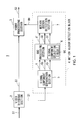
- the reference numeral 1 denotes a video display device as a whole.
- the video display device 1 includes a video dividing section 2, a video processing section 3 and a motion vector detection block 4.
- One frame of video signal S1 is input as a source into the video dividing section 2.
- the video dividing section 2 divides the video signal S1 into two, one of which is supplied to the video processing section 3 and the other of which is supplied to a signal component separation section 5 of the motion vector detection block 4.
- the signal component separation section 5 of the motion vector detection block 4 separates the video signal S1 into predetermined macro block units, or four blocks of brightness components Y, two blocks of color-difference components Cb and Cr.
- the signal component separation section 5 subsequently supplies them to an Automatic Gain Control (AGC) processing section 6.
- AGC Automatic Gain Control
- the AGC processing section 6 includes a signal component selection circuit 6A.
- the signal component selection circuit 6A selects one of those components supplied from the signal component separation section 5: the brightness component Y, or the color-difference component Cb or Cr. As its initial setting, the AGC processing section 6 selects the brightness component Y.
- the AGC processing section 6 controls its gain, and then supplies the gain-controlled brightness component Y' to a motion vector detection section 7, along with the color-difference components Cb and Cr.
- the motion vector detection section 7 detects motion vectors MV of the video signal S1 from the brightness component Y' and color-difference components Cb and Cr supplied from the AGC processing section 6, and supplies the motion vectors MV to the video processing section 3.
- the video processing section 3 After receiving the video signal S1 from the video dividing section 2, the video processing section 3 holds the video signal S1 and waits until it receives the motion vectors MV from the motion vector detection section 7 of the motion vector detection block 4.
- the video processing section 3 After receiving the motion vectors MV, the video processing section 3 performs a motion compensation process to the video signal S1 using the motion vectors MV, and then outputs a resulting video signal S2 to a display section such as Liquid Crystal Display (LDC).
- a display section such as Liquid Crystal Display (LDC).
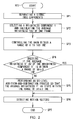
- the video display device 1 starts a routine RT1 from start step and then proceeds to step SP1.
- the signal component separation section 5 of the motion vector detection block 4 separates one frame of video signal S1, supplied from the video signal dividing section 2, into the brightness components Y and the color-difference components Cb and Cr.
- the video display device 1 subsequently proceeds to step SP2.
- the signal component selection section 6A selects the brightness component Y for the AGC processing section 6 to control its gain, and calculates its one-frame average brightness level YAV. Subsequently, the video display device 1 proceeds to step SP3.
- the average brightness level YAV the average of the brightness level Y
- the brightness component Y may include pixels G1 and G2 with outstanding brightness levels due to noise or the like.
- the motion vectors MV are detected from the brightness component Y containing those pixels G1 and G2, they may inappropriately affect the video display process of the video processing section 3 of the video display device 1.
- the AGC processing section 6 of the video display device 1 controls the gain of the brightness component Y as a whole, such that they stay within a range of 0 to 100 IRE, if the brightness component Y includes pixels whose brightness levels are less than 0 IRE or greater than 100 IRE, such as pixels G1 and G2.
- the video display device 1 subsequently proceeds to step SP4.
- IRE is a unit named after an academic society, representing the amplitude of video signals.
- the video display device 1 makes a determination as to whether the average brightness Y ⁇ AV, or the average of the gain-controlled brightness component Y', is within a range of 50 ⁇ 3 IRE. If the negative result is obtained, the device 1 proceeds to step SP5, and if not, it proceeds to step SP6.
- step SP5 the AGC processing section 6 performs an addition-and-subtraction process of Direct Current (DC) level so that the average brightness Y'AV stays within the range of 50 ⁇ 3 IRE.
- the video display device 1 subsequently proceeds to step SP6.
- DC Direct Current
- the gain-controlled brightness component Y' is maintained by the video display device 1 within a range of 25 to 75 IRE, and its average brightness Y'AV within the range of 50 ⁇ 3 IRE.
- the video display device 1 detects the video signal S1's motion vectors MV from the gain-controlled brightness component Y', supplies the motion vectors MV to the video processing section 3, and then proceeds to step SP7 to end the process.
- the video display device 1 divides the video signal S1 into the brightness component Y and the color-difference components Cb and Cr, and controls the gain of the brightness component Y by the AGC processing section 6. This allows the video display device 1 to get rid of the negative effects of outstanding pixels, such as the pixels G1 and G2 caused by noise or the like, before the video processing section 3 starts image processing based on the motion vectors. Therefore, the image processing by the video processing section 3 becomes stabilized.
- the video dividing section 2 divides the video signal S1 into two, and the motion vector detection block 4 uses a different video signal V1 from the one, or another video signal V1, supplied to the video processing section 3.
- the detection process of the motion vectors MV by the motion vector detection block 4 does not affect the image processing of the video signal S1 by the video processing section 3. Therefore, the image processing by the video processing section 3 becomes stabilized.
- the video display device 1 by using the AGC processing section 6, controls the gain of the brightness component Y of the video signal S1 such that it stays within the predetermined ranges.
- This allows the video display device 1 to get rid of the negative effects of outstanding pixels, such as the pixels G1 and G2 caused by noise or the like, before detecting the motion vectors MV. Therefore, the high-quality, stable images can be obtained based on the detected motion vectors MV.
- the device controls the gain of the brightness component Y of the video signal S1, and detects the motion vectors MV from the gain-controlled brightness components Y'.
- the present invention is not limited to this. Instead, the device may control the gain of the color-difference component Cb or Cr, and then detect the motion vectors MV from the gain-controlled color-difference component Cb' or Cr'.
- the device controls the gain of the brightness component Y of the video signal S1, and detects the motion vectors MV from the gain-controlled brightness components Y'.
- the present invention is not limited to this. Instead, the device may control the gains of both the brightness component Y and the color-difference components Cb and Cr, and then detect the motion vectors MV from the gain-controlled brightness component Y' and the color-difference components Cb' and Cr'.
- the video signal S1 is divided into the brightness component Y and the color-difference components Cb and Cr.
- the present invention is not limited to this. Instead, the video signal S1 may be divided into the brightness component Y and the color-difference component C.
- the video signal S1 is divided into the brightness component Y and the color-difference components Cb and Cr, and the gain of the brightness component Y is controlled, and the motion vectors MV are detected from the gain-controlled brightness component Y'.
- the present invention is not limited to this. Instead, the video signal S1 may be divided into a red component, a green component, and a blue component, and one, two, or all of which may be controlled in gain, and the motion vectors MV may be detected from the gain-controlled component(s).
- the motion vector detection block 4 which is the equivalent of a motion vector detection device of an embodiment of the present invention, includes the signal component separation section 5 as separation means; the signal component selection circuit 6A as selection means; the AGC processing section 6 as gain controlling means; and the motion vector detection section 7 as motion vector detection means.
- the present invention is not limited to this.
- the motion vector detection device may have different configuration, so that the separation means, the selection means, the gain controlling means, and the motion vector detection means can be realized.
- the above motion vector detection device and motion vector detection method can be applied to a television receiver that displays motion pictures, as well as other electronics devices for displaying motion pictures, such as personal computers, Personal Digital Assistant, cell phones, and portable music players.
Landscapes
- Engineering & Computer Science (AREA)
- Multimedia (AREA)
- Signal Processing (AREA)
- Color Television Systems (AREA)
- Processing Of Color Television Signals (AREA)
- Compression Or Coding Systems Of Tv Signals (AREA)
- Television Systems (AREA)
Applications Claiming Priority (1)
| Application Number | Priority Date | Filing Date | Title |
|---|---|---|---|
| JP2007199723A JP2009038509A (ja) | 2007-07-31 | 2007-07-31 | 動きベクトル検出装置及び動きベクトル検出方法 |
Publications (2)
| Publication Number | Publication Date |
|---|---|
| EP2026575A2 true EP2026575A2 (de) | 2009-02-18 |
| EP2026575A3 EP2026575A3 (de) | 2009-02-25 |
Family
ID=39951537
Family Applications (1)
| Application Number | Title | Priority Date | Filing Date |
|---|---|---|---|
| EP20080161174 Withdrawn EP2026575A3 (de) | 2007-07-31 | 2008-07-25 | Bewegungsvektor-Erkennungsvorrichtung und Bewegungsvektor-Erkennungsverfahren |
Country Status (4)
| Country | Link |
|---|---|
| US (1) | US8126059B2 (de) |
| EP (1) | EP2026575A3 (de) |
| JP (1) | JP2009038509A (de) |
| CN (1) | CN101360183A (de) |
Families Citing this family (4)
| Publication number | Priority date | Publication date | Assignee | Title |
|---|---|---|---|---|
| US8861875B1 (en) * | 2011-07-29 | 2014-10-14 | Teradici Corporation | Method and apparatus for encoding changed image regions |
| JP5887088B2 (ja) * | 2011-09-09 | 2016-03-16 | 東芝アルパイン・オートモティブテクノロジー株式会社 | 画像処理装置 |
| US9508156B1 (en) * | 2014-12-23 | 2016-11-29 | Ambarella, Inc. | Level-based motion detection in a sequence of pictures |
| US10021396B1 (en) * | 2014-12-30 | 2018-07-10 | Ambarella, Inc. | Motion detection based on observing several pictures |
Citations (1)
| Publication number | Priority date | Publication date | Assignee | Title |
|---|---|---|---|---|
| JP2007199723A (ja) | 2006-01-26 | 2007-08-09 | Samsung Electronics Co Ltd | 表示装置 |
Family Cites Families (11)
| Publication number | Priority date | Publication date | Assignee | Title |
|---|---|---|---|---|
| US4628362A (en) * | 1985-05-02 | 1986-12-09 | American Dynamics Corporation | Combined video AGC and digitizing circuit |
| JPH0771296B2 (ja) * | 1989-03-20 | 1995-07-31 | 松下電器産業株式会社 | 動きベクトル検出装置 |
| JP3164121B2 (ja) * | 1992-02-21 | 2001-05-08 | キヤノン株式会社 | 動きベクトル検出装置 |
| JPH05292489A (ja) | 1992-04-10 | 1993-11-05 | Nippon Telegr & Teleph Corp <Ntt> | 動きベクトル推定方法 |
| EP0656725B1 (de) * | 1993-12-02 | 2000-03-15 | Canon Kabushiki Kaisha | Vorrichtung zur Bildzitterkorrektur |
| US5758091A (en) * | 1995-08-10 | 1998-05-26 | Intel Corporation | Method and apparatus for adjusting video data to limit the effects of automatic gain control on motion estimation video coders |
| US5706054A (en) * | 1995-12-01 | 1998-01-06 | Intel Corporation | Method and apparatus for adjusting video data to limit the effects of automatic focusing control on motion estimation video coders |
| JP3941900B2 (ja) | 1998-01-12 | 2007-07-04 | 三菱電機株式会社 | 動きベクトル検出装置 |
| JP2001309384A (ja) | 2000-04-18 | 2001-11-02 | Oki Electric Ind Co Ltd | 画像圧縮装置 |
| JP2005354370A (ja) | 2004-06-10 | 2005-12-22 | Shibasoku:Kk | 動きベクトル検出装置 |
| JP4708819B2 (ja) * | 2005-03-14 | 2011-06-22 | キヤノン株式会社 | 画像処理装置、方法、コンピュータプログラム及び記憶媒体 |
-
2007
- 2007-07-31 JP JP2007199723A patent/JP2009038509A/ja active Pending
-
2008
- 2008-07-25 EP EP20080161174 patent/EP2026575A3/de not_active Withdrawn
- 2008-07-29 US US12/181,355 patent/US8126059B2/en not_active Expired - Fee Related
- 2008-07-31 CN CNA2008101349156A patent/CN101360183A/zh active Pending
Patent Citations (1)
| Publication number | Priority date | Publication date | Assignee | Title |
|---|---|---|---|---|
| JP2007199723A (ja) | 2006-01-26 | 2007-08-09 | Samsung Electronics Co Ltd | 表示装置 |
Also Published As
| Publication number | Publication date |
|---|---|
| US8126059B2 (en) | 2012-02-28 |
| CN101360183A (zh) | 2009-02-04 |
| US20090033800A1 (en) | 2009-02-05 |
| EP2026575A3 (de) | 2009-02-25 |
| JP2009038509A (ja) | 2009-02-19 |
Similar Documents
| Publication | Publication Date | Title |
|---|---|---|
| US8111263B2 (en) | Video display device and color temperature correction method for the same | |
| US7839455B2 (en) | Image processing apparatus, image display and image processing method | |
| US20070286533A1 (en) | Image correction circuit, image correction method and image display | |
| US7400363B2 (en) | Image processing apparatus and image processing method | |
| JP4468467B2 (ja) | 映像信号制御装置、映像表示システム、及び映像信号制御方法 | |
| US20080007655A1 (en) | Image signal processing apparatus, image display and image display method | |
| US8369645B2 (en) | Image correction circuit, image correction method and image display | |
| US8102473B2 (en) | Image correction circuit, image correction method and image display | |
| EP1898650A2 (de) | Bildverarbeitungsgerät, Anzeigevorrichtung mit Bildverarbeitungsgerät und Bildverarbeitungsverfahren | |
| EP2026575A2 (de) | Bewegungsvektor-Erkennungsvorrichtung und Bewegungsvektor-Erkennungsverfahren | |
| US7023496B2 (en) | Moving picture decoding display apparatus and method for controlling a video signal's contrast and brightness when a video signal update is detected | |
| US20080024675A1 (en) | Image correction circuit, image correction method and image display | |
| US20080238861A1 (en) | Backlight control apparatus and backlight control method | |
| JPH09307913A (ja) | ホワイトバランス制御装置 | |
| EP1758370A2 (de) | Bildverarbeitungsvorrichtung, Bildanzeige und Bildverarbeitungsverfahren | |
| JP2005057621A (ja) | 映像信号処理回路 | |
| US20080012958A1 (en) | White balance system and the method thereof | |
| JP2010028609A (ja) | 映像表示装置 | |
| US20060232703A1 (en) | Picture display device | |
| JP2010016520A (ja) | 映像信号処理装置、及び映像信号処理方法 | |
| JP2007219631A (ja) | 画像処理装置の輝度調整回路及びその輝度調整方法 | |
| KR20040102942A (ko) | 영상표시기기의 컨트라스트 제어장치 | |
| WO2005098810A1 (ja) | 表示制御装置及び表示制御方法等 | |
| JP2002057916A (ja) | 映像表示装置 | |
| JPH02308678A (ja) | 液晶ディスプレイ付カメラ一体型ビデオテープレコーダ |
Legal Events
| Date | Code | Title | Description |
|---|---|---|---|
| PUAI | Public reference made under article 153(3) epc to a published international application that has entered the european phase |
Free format text: ORIGINAL CODE: 0009012 |
|
| PUAL | Search report despatched |
Free format text: ORIGINAL CODE: 0009013 |
|
| AK | Designated contracting states |
Kind code of ref document: A2 Designated state(s): AT BE BG CH CY CZ DE DK EE ES FI FR GB GR HR HU IE IS IT LI LT LU LV MC MT NL NO PL PT RO SE SI SK TR |
|
| AX | Request for extension of the european patent |
Extension state: AL BA MK RS |
|
| AK | Designated contracting states |
Kind code of ref document: A3 Designated state(s): AT BE BG CH CY CZ DE DK EE ES FI FR GB GR HR HU IE IS IT LI LT LU LV MC MT NL NO PL PT RO SE SI SK TR |
|
| AX | Request for extension of the european patent |
Extension state: AL BA MK RS |
|
| RIC1 | Information provided on ipc code assigned before grant |
Ipc: H04N 7/01 20060101ALI20090121BHEP Ipc: H04N 5/52 20060101AFI20090121BHEP |
|
| 17P | Request for examination filed |
Effective date: 20090805 |
|
| 17Q | First examination report despatched |
Effective date: 20090903 |
|
| AKX | Designation fees paid |
Designated state(s): DE FR GB |
|
| RIC1 | Information provided on ipc code assigned before grant |
Ipc: H04N 5/14 20060101AFI20120508BHEP |
|
| GRAP | Despatch of communication of intention to grant a patent |
Free format text: ORIGINAL CODE: EPIDOSNIGR1 |
|
| RIC1 | Information provided on ipc code assigned before grant |
Ipc: H04N 7/01 20060101ALI20120917BHEP Ipc: H04N 5/52 20060101AFI20120917BHEP |
|
| STAA | Information on the status of an ep patent application or granted ep patent |
Free format text: STATUS: THE APPLICATION IS DEEMED TO BE WITHDRAWN |
|
| 18D | Application deemed to be withdrawn |
Effective date: 20130201 |