EP2028264A1 - Zellinkubator - Google Patents
Zellinkubator Download PDFInfo
- Publication number
- EP2028264A1 EP2028264A1 EP07744610A EP07744610A EP2028264A1 EP 2028264 A1 EP2028264 A1 EP 2028264A1 EP 07744610 A EP07744610 A EP 07744610A EP 07744610 A EP07744610 A EP 07744610A EP 2028264 A1 EP2028264 A1 EP 2028264A1
- Authority
- EP
- European Patent Office
- Prior art keywords
- unit
- focus
- detecting
- restricted
- focus position
- Prior art date
- Legal status (The legal status is an assumption and is not a legal conclusion. Google has not performed a legal analysis and makes no representation as to the accuracy of the status listed.)
- Withdrawn
Links
Images


Classifications
-
- C—CHEMISTRY; METALLURGY
- C12—BIOCHEMISTRY; BEER; SPIRITS; WINE; VINEGAR; MICROBIOLOGY; ENZYMOLOGY; MUTATION OR GENETIC ENGINEERING
- C12M—APPARATUS FOR ENZYMOLOGY OR MICROBIOLOGY; APPARATUS FOR CULTURING MICROORGANISMS FOR PRODUCING BIOMASS, FOR GROWING CELLS OR FOR OBTAINING FERMENTATION OR METABOLIC PRODUCTS, i.e. BIOREACTORS OR FERMENTERS
- C12M41/00—Means for regulation, monitoring, measurement or control, e.g. flow regulation
- C12M41/12—Means for regulation, monitoring, measurement or control, e.g. flow regulation of temperature
- C12M41/14—Incubators; Climatic chambers
-
- C—CHEMISTRY; METALLURGY
- C12—BIOCHEMISTRY; BEER; SPIRITS; WINE; VINEGAR; MICROBIOLOGY; ENZYMOLOGY; MUTATION OR GENETIC ENGINEERING
- C12M—APPARATUS FOR ENZYMOLOGY OR MICROBIOLOGY; APPARATUS FOR CULTURING MICROORGANISMS FOR PRODUCING BIOMASS, FOR GROWING CELLS OR FOR OBTAINING FERMENTATION OR METABOLIC PRODUCTS, i.e. BIOREACTORS OR FERMENTERS
- C12M41/00—Means for regulation, monitoring, measurement or control, e.g. flow regulation
- C12M41/30—Means for regulation, monitoring, measurement or control, e.g. flow regulation of concentration
- C12M41/36—Means for regulation, monitoring, measurement or control, e.g. flow regulation of concentration of biomass, e.g. colony counters or by turbidity measurements
-
- G—PHYSICS
- G02—OPTICS
- G02B—OPTICAL ELEMENTS, SYSTEMS OR APPARATUS
- G02B7/00—Mountings, adjusting means, or light-tight connections, for optical elements
- G02B7/28—Systems for automatic generation of focusing signals
- G02B7/36—Systems for automatic generation of focusing signals using image sharpness techniques, e.g. image processing techniques for generating autofocus signals
- G02B7/38—Systems for automatic generation of focusing signals using image sharpness techniques, e.g. image processing techniques for generating autofocus signals measured at different points on the optical axis, e.g. focussing on two or more planes and comparing image data
Definitions
- the present invention relates to a cell incubator which incubates cells, and which allows the cells thus incubated to be observed.
- cell incubators have been proposed that have a storage unit in which cells are incubated, inside a thermostatic chamber maintained at a prescribed atmosphere, and an observation unit to observe a cell incubation process (Patent Document 1, for example).
- the cell incubator disclosed in Patent Document 1 requires a great amount of time to detect optimum focus position. Furthermore, such an arrangement has a problem in that, the fluorescence image acquired in the fluorescence observation mode cannot be clearly and precisely observed in correlation with the organelles to be observed. Moreover, with conventional fluorescence observation, excitation light is emitted to the cells, and focus adjustment is performed based upon the fluorescence emitted from the cells. This leads to adverse effects such as fluorescence discoloration in the focus adjustment, and damage to the cells due to the excitation light.
- Patent Document 1 Japanese Patent Application Laid-Open No. 2004-180675
- An aspect according to the invention as disclosed in Claim 1 relates to a cell incubator (10) having an observation unit (70) to observe a cell incubation process.
- the cell incubator (10) comprises: a focus detecting unit (110) to detect a focus position of an imaging optical system (71) of the observation unit (70); an optimum focus selecting unit (120) to select an optimum focus position based upon a plurality of images taken by moving the imaging optical system (71) stepwise at a fine pitch along an optical axis direction from the focus position, based upon the focus position detected by the focus detecting unit (110); and a fluorescence observation unit (130) to shoot a fluorescence image of the cells by moving the imaging optical system (71) to the optimum focus position thus detected by the optimum focus selecting unit (120).
- the focus detecting unit (110) comprises: a wide area detecting unit (111) to set a wide area extending along an optical axis direction of the imaging optical system (71) to be a focus detecting region, and to detect a focus position over the wide focus detecting region; a restricted detecting unit (112) to set a restricted region, which is narrower than the wide focus detecting area of the wide area detecting unit (111) and which contains the focus position detected by the wide area detecting unit (111), to be a restricted focus detecting region, and to detect a focus position over the restricted focus detecting region; and a detailed detecting unit (113) to set a restricted region, which is narrower than the restricted focus detecting region for the restricted detecting unit (112) and which contains the focus position detected by the restricted detecting unit (112), to be a detailed area focus detecting region, and to detect a focus position over the detailed area focus detecting region.
- An aspect according to the invention as disclosed in Claim 3 relates to the cell incubator (10) described in Claim 1 or Claim 2, in which the focus detecting unit (110) detects a focus position by moving the imaging optical system (71) stepwise or continuously, and the optimum focus selecting unit (120) moves the imaging optical system (71) by a smaller movement distance than the focus detecting unit (110) moves the imaging optical system (71) stepwise or continuously.
- An aspect according to the invention disclosed in Claim 4 relates to the cell incubator (10) described in any one of Claim 1 through Claim 3.
- the cell incubator (10) further includes an image processing unit (140) to create a superimposition image by superimposing the fluorescence image acquired by the fluorescence observation unit (130) and the image acquired at the optimum focus position.
- An aspect according to the invention as disclosed in Claim 5 relates to a cell incubator (10) having an observation unit (70) to observe a cell incubation state.
- the cell incubator (10) comprises: a wide area detecting unit (111) to set a wide area extending along an optical axis direction of the observation unit (70) to be a focus detecting region, and to detect a focus position over the wide focus detecting region; a restricted detecting unit (112) to set a restricted region, which is narrower than the wide focus detecting area of the wide area detecting unit (111) and which contains the focus position detected by the wide area detecting unit (111), to be a restricted focus detecting region, and to detect a focus position over the restricted focus detecting region; a detailed detecting unit (113) to set a restricted region, which is narrower than the restricted focus detecting region for the restricted detecting unit (112) and which contains the focus position detected by the restricted detecting unit (112), to be a detailed area focus detecting region, and to detect a focus position over the
- An aspect according to the invention as disclosed in Claim 6 relates to a cell incubator (10) including a stage on which a cell incubation container (15) is mounted, an observation unit (70) which allows a cell incubation state of cells contained in the cell incubation container (15) to be observed, and a moving unit (78) which relatively moves the stage and the observation unit (70).
- the cell incubator (10) comprises a wide area detecting unit (111) to set a wide area extending along an optical axis direction of the observation unit (70) to be a focus detecting region, and to detect a focus position over the wide focus detecting region; a restricted detecting unit (112) to set a restricted region, which is narrower than the wide focus detecting area of the wide area detecting unit (111) and which contains the focus position detected by the wide area detecting unit (111), to be a restricted focus detecting region, and to detect a focus position over the restricted focus detecting region; a detailed detecting unit (113) to set a restricted region, which is narrower than the restricted focus detecting region for the restricted detecting unit (112) and which contains the focus position detected by the restricted detecting unit (112), to be a detailed area focus detecting region, and to detect a focus position over the detailed area focus detecting region; and an image acquisition unit (120) to set a predetermined focus detecting region that contains the focus position detected by the detailed detecting unit (113) and
- the cell incubator according to the present invention includes: the focus detecting unit to detect the focus position for the imaging optical system; the optimum focus selecting unit which selects the optimum focus position based upon the focus positions; and the fluorescence observation unit which performs fluorescence observation after the imaging optical system is moved to the optimum focus position.
- the focus detecting unit to detect the focus position for the imaging optical system
- the optimum focus selecting unit which selects the optimum focus position based upon the focus positions
- the fluorescence observation unit which performs fluorescence observation after the imaging optical system is moved to the optimum focus position.
- the present invention achieves the purpose of providing a cell incubator which allows an image of cells and a fluorescent image thereof to be acquired at a high speed, and which allows these images to be observed with high precision in correlation with each other, as follows. First, the cells are observed in a phase contrast observation mode, and focus detecting is performed based upon the image thus observed, thereby obtaining a focus position. Subsequently, image information is acquired over a further narrowed area so as to obtain the optimum focus position. A fluorescence image is acquired at the optimum focus position thus obtained.
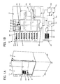
- Fig. 1 is a diagram which shows a cell incubator according to an embodiment of the present invention.
- Fig.1A is an external view of the cell incubator.
- Fig.1B is a diagram which shows a detailed configuration of the interior of the cell incubator and connections of a control unit.
- Fig. 2 is a detailed configuration of an observation unit of the cell incubator.
- Fig. 3 is a diagram which shows an example of images taken by the observation unit.
- Fig.3A is a view which shows a phase contrast image.
- Fig.3B is a view which shows a fluorescence image.
- Fig.3C is a view which shows a superimposition image created by superimposing the fluorescence image and the phase contrast image.
- a cell incubator 10 is an apparatus including a thermostatic chamber 11, an opening/closing door 12, an inserting/extracting unit 13, an information storage unit 20, an information display unit 30, an operation input unit 40, and a control unit 50. Furthermore, the thermostatic chamber 11 includes a storage unit 60, an observation unit 70, and a conveying unit 80 therewithin.
- the cell incubator 10 allows a plurality of cells to be incubated, and allows a cell incubation process to be automatically observed.
- the thermostatic chamber 11 is a chamber which maintains a constant atmosphere at a temperature of 37°C, a humidity of 97%, and a CO 2 concentration of 5%.
- the opening/closing door 12 is a door provided over the entire area of the front face of the thermostatic chamber 11.
- the opening/closing door 12 is opened/closed.
- the inserting/extracting unit 13, the information display unit 30, and the operation input unit 40 are arranged on the opening/closing door 12, which improves user operability.
- the inserting/extracting unit 13 is an inserting/extracting opening which allows cells to be inserted into/extracted from the thermostatic chamber 11. When there is no cell insertion/extraction, the inserting/extracting unit 13 is closed by means of an inserting/extracting door 14 in order to maintain the atmosphere in the thermostatic chamber 11.
- the inserting/extracting door 14 is a door having a locking mechanism opening/closing to inside the thermostatic chamber 11.
- a cell incubation container 15 is a container in which cells are incubated. Examples thereof include a dish, a well plate, a flask, etc.
- a holder 16 is a holder member which allows the cell incubation container 15 to be properly arranged in each of the container unit 60, the observation unit 70, and the conveying unit 80 included in the cell incubator 10.
- the information storage unit 20 is memory which stores information with respect to cells, and information with respect to the observation results for the cells observed using the observation unit 70.
- information with respect to cells is principally information regarding the properties of the cells, such as kind of cells, culture composition information, initial number of cells, culture replacement frequency, successive cultivation period, etc., and includes information associated therewith such as kind of cell incubation container 15, information with respect to a manager who manages the cells, experimental information with respect to the cell cultivation (experiment name), information with respect to the cell cultivation history, etc.
- the information display unit 30 is a display which displays information stored in the information storage unit 20, information with respect to operation of the cell incubator 10, etc.
- the information display unit 30 can be tilted by means of a tilt mechanism 32 so as to facilitate observation by the user, as shown in Fig.1A (arrow A).
- a display format control unit 31 is a display control unit which allows the elapsed-time in the individual cell information to be displayed in a simple manner using changes in color.
- the operation input unit 40 is an input device which allows the cell information to be input, and which allows operation of the cell incubator 10 to be determined according to the content displayed on the information display unit 30, thereby inputting an operation instruction to the control unit 50.
- the operation input unit 40 has a configuration including a plurality of buttons.
- the control unit 50 is a control circuit which performs control so as to maintain the atmosphere in the thermostatic chamber 11 under a constant environmental conditions, and which integrally controls the observation control unit 100 and the observation unit 70 and the conveying unit 80 included within the thermostatic chamber 11 according to the content of operations input via the operation input unit 40.
- the user identification unit 51 is a confirmation circuit provided in the control unit 50.
- the user identification unit 51 determines whether or not a log-in request for the cell incubator 10 is valid by make user to input an user ID.
- the cell incubator 10 is managed such that it cannot be operated unless the user inputs a correct password set beforehand. Such an arrangement protects the cell incubator 10 from being operated arbitrarily by unauthorized people.
- the user ID is associated with the cell manager information with respect to the cells stored in the cell incubator 10.
- the cell incubator 10 limits operation such that operation thereof is permitted only in a case in which the user ID matches the cell manager information with respect to the cell manager information that manages the cells stored in the information storage unit 20, so as to protect registered cells from mistaken operation by others, in cases in which a plurality of users have been registered.
- the storage unit 60 interior is divided into a plurality of storage sections 61.
- the cell incubation container 15 containing cells is stored in respective storage sections 61 via the holder 16, thereby allowing the cells to be incubated.
- the storage unit 60 has 27 storage sections 61 in the form of a matrix having 9 rows along the vertical direction and 3 columns along the horizontal direction.
- the observation unit 70 is a microscope which includes an objective lens 71, a Z-axis mechanism unit 72, a CCD camera unit 73, an LED illumination unit 74, a fluorescent illumination unit 75, a fluorescence filter unit 76, a lens unit 77, and an XY stage unit 78.
- the observation unit 70 allows the cells to be observed (allows an image of the cells to be taken).
- the observation unit 70 allows the user to observe the state of each organelle such as nucleus, mitochondria, etc., in fluorescence observation mode (molecular observation mode), in addition to observation of cells in phase contrast observation mode.
- the objective lens unit 71 has a configuration including a plurality of objective lenses, which can be separately selected based upon kind of cell, observation area, etc.
- the Z-axis mechanism unit 72 includes a guide mechanism 72-1 and a driving motor 72-2.
- the Z-axis mechanism unit 72 is a driving mechanism which adjusts focus by moving the objective lens unit 71 along the vertical direction (Z-axis direction) by a small movement distance.
- the CCD camera unit 73 is a camera which takes an ordinary observation image (phase contrast image) and a fluorescence observation image (fluorescence image) of the cells contained in the cell incubation container 15.
- the LED illumination unit 74 is an illumination unit employing LEDs, which illuminates the cells contained in the cell incubation container 15.
- the LED illumination unit 74 emits illumination light for image taking, synchronously with the exposure time for the CCD camera unit 73. Furthermore, the LED illumination unit 74 intermittently emits illumination light with movement of the Z-axis mechanism unit 72 in focus detection.
- the fluorescence illumination unit 75 is an illumination unit which emits excitation light which excites fluorescent protein of the cells, thereby allowing the organelles of the cells to be observed.
- the fluorescence filter unit 76 has a configuration including a wavelength-selectable dichroic mirror and a bandpass filter. Such an arrangement allows the CCD camera unit 73 to take an image of the fluorescent protein of the cells and which has been excited by the excitation light emitted from the fluorescence illumination unit 75 to the entire area along the optical axis direction.
- the XY stage unit 78 is a precision stage which allows the cell incubation container 15, which has been conveyed by the conveying unit 80, to be movable to a desired position along a horizontal direction (XY direction). Such an arrangement allows the cell incubation container 15 to be moved to an observation position of the observation unit 70.
- the conveying unit 80 includes a conveying arm 81, a moving member 82, a screw shaft 83, an arm motor 84, and a moving motor 85.
- the conveying unit 80 is a conveying mechanism which conveys the cell incubation container 15 with the holder 16 to the inserting/extracting unit 12, the storage unit 60, or the observation unit 70, within the thermostatic chamber 11.
- the moving member 82 which meshes with a screw shaft 83 which has a helical groove formed in the face thereof, is driven along the vertical direction (arrow B) by the moving motor 85.
- the conveying arm 81 supported by the moving member 82 is moved along the horizontal direction (arrow C) by the arm motor 84.
- the screw shaft 83 includes a mechanism (not shown) which allows movement along a direction orthogonal to the drawing in Fig. 1 (horizontal direction).
- the observation control unit 100 includes a focus detecting unit 110, an optimum focus selecting unit 120, a fluorescence observation unit 130, and an image processing unit 140.
- the observation control unit 100 is a controller which integrally controls the observation unit 70 according to an instruction signal received from the operation input unit 40 and the control unit 50.
- the focus detecting unit 110 includes a wide area detecting unit 111, a restricted detecting unit 112, and a detailed detecting unit 113.
- the focus detecting unit 110 is a circuit which automatically detects the focus position (automatic focusing) based upon the images of the CCD camera unit 73 with the objective lens unit 71 moving up/down by means of the Z-axis mechanism unit 72.
- the optimum initial position of the objective lens unit 71 can be computed giving consideration to the kind of cells, the thickness of the bottom of the cell incubation container 15, etc., based upon cell information, information with respect to the kind of cell incubation container 15, etc., read from the information storage unit 20.
- the objective lens unit 71 can be moved to the initial position thus computed.
- the focus position is computed as follows. That is, the maximum contrast value and the minimum contrast value are extracted from the pixel values of each image, and the focus position is set to the position that exhibits the maximum value calculated based upon the contrast curve thus acquired (maximum/minimum method). Alternatively, the differences in the image data between adjacent pixels are calculated for each line of the contrast image thus acquired. The sum of the absolute values of the differences thus calculated is calculated for each image thus acquired. The position that corresponds to the maximum value of the absolute sum is set to the focus position ( ⁇
- the wide area detecting unit 111 performs a focus detecting operation (wide area scanning operation) by driving the objective lens unit 71 over a wide area along the Z-axis direction, i.e., the optical axis direction of the objective lens unit 71. Specifically, the wide area detecting unit 111 performs a focus detecting operation by driving the objective lens unit 71 stepwise at a rough pitch with regard to the focal depth of the objective lens unit 71, or by continuously driving the objective lens unit 71.
- a focus detecting operation wide area scanning operation
- the restricted detecting unit 112 performs a focus detecting operation (restricted area scanning operation) by driving the objective lens unit 71 over a restricted area narrower that used by the wide area detecting unit 111. Specifically, the restricted detecting unit 112 sets the focus detecting area to a restricted area which contains the focus position of the objective lens unit 71 obtained by the wide area detecting unit 111. Furthermore, the restricted detecting unit 112 performs a focus detecting operation by driving the objective lens unit 71 stepwise at a moderately rough pitch with regard to the focal depth of the objective lens unit 71, or by continuously driving the objective lens unit 71.
- a focus detecting operation restricted area scanning operation
- the detailed detecting unit 113 performs a focus detecting operation (detailed scanning operation) by driving the objective lens unit 71 over a more restricted area than that used by the restricted detecting unit 12. Specifically, the detailed detecting unit 113 sets the focus detecting area to a restricted area which contains the focus position of the objective lens unit 71 obtained by the restricted detecting unit 112. Furthermore, the detailed detecting unit 113 performs a focus detecting operation by driving the objective lens unit 71 stepwise at a fine pitch with regard to the focal depth of the objective lens unit 71, or by continuously driving the objective lens unit 71.
- a focus detecting operation (detailed scanning operation) by driving the objective lens unit 71 over a more restricted area than that used by the restricted detecting unit 12. Specifically, the detailed detecting unit 113 sets the focus detecting area to a restricted area which contains the focus position of the objective lens unit 71 obtained by the restricted detecting unit 112. Furthermore, the detailed detecting unit 113 performs a focus detecting operation by driving the objective lens unit 71 stepwise at
- the focus detecting unit 110 includes the wide area detecting unit 111, the restricted detecting unit 112, and the detailed detecting unit 113. Such an arrangement provides three-step focus detecting, thereby detecting the focus position with high precision.
- the optimum focus selecting unit 120 identifies the optimum focus position for each of the detecting units 111 through 113 of the focus detecting unit 110. For example, the optimum focus selecting unit 120 acquires a plurality of focus detecting signals by the wide area scanning operation performed by the wide area detecting unit 111. The optimum focus selecting unit 120 relatively evaluates each focus detecting signal so as to extract the optimum focus detecting signal. The focus position obtained based upon the focus detecting signal thus extracted is determined as the optimum focus position by the optimum focus selecting unit 120. In the same way, the optimum focus selecting unit 120 determines the optimum focus position for the restricted detecting unit 112 and the detailed detecting unit 113. The optimum focus positions form references used for determining the focus detecting regions over which the aforementioned detecting units 111 through 113 perform the scanning driving operation.
- the CCD camera 73 executes acquisition of a phase contrast image.
- the CCD camera unit 73 acquires a phase contrast image as shown in Fig.3A .
- the CCD camera unit 73 acquires phase contrast images for each stepwise driving operation, to be stored in the information storage unit 20.
- the stepping movement distance of the stepwise driving operation is set to a smaller movement distance than that used by the detailed detecting unit 113.
- the optimum focus position is determined based upon the contrast values of the images in the same way as in the focus detecting unit 110.
- the fluorescence observation unit 130 is a circuit which instructs the fluorescence illumination unit 75 to excite the fluorescent protein in the cells, and which instructs the CCD camera unit 73 to take a fluorescence image via the fluorescence filter unit 76. It should be noted that the fluorescence image is taken after the objective lens unit 71 is moved to the optimum focus position determined by the optimum focus selecting unit 120.
- the image processing unit 140 is an image processing circuit which creates a superimposed image by superimposing the fluorescence image acquired by the fluorescence observation unit 130 and the phase contrast image taken at the optimum focus position selected by the optimum focus selecting unit 120. As shown in Fig.3B , only the points that emit fluorescence by the fluorescence illumination are displayed in the image. With such an arrangement, a superimposition image as shown in Fig.3C is created by superimposing the fluorescence image on the phase contrast image shown in Fig.3A . Such an arrangement allows the user to easily identify the cells and the organelles that emit fluorescence.
- Fig. 4 is a flowchart which shows the method for using the cell incubator.
- Fig. 5 is a diagram for describing the detecting start position of the objective lens unit of the cell incubator.
- the cell incubator 10 conveys the cell incubation container 15 from the storage unit 60 or the inserting/extracting unit 13 to the XY stage unit 78 of the observation unit 70 by means of the conveying unit 80 (S201). Furthermore, the cell incubator 10 reads the information with respect to the cells and the cell incubator 15 from the information storage unit 20, and confirms the information thus read out. Moreover, based upon the information thus read, the cell incubator 10 computes the initial position of the objective lens unit 71 of the observation unit 70 for detecting the focus (S202). Subsequently, as shown in Fig. 2 , the XY stage unit 78 moves the cell incubation container 15 on the imaging optical path (S203, arrow D). Furthermore, the Z-axis mechanism unit 72 moves the objective lens unit 71 to the initial position thus computed (S204, arrow E).
- the wide area detecting unit 111 detects the focus position for the objective lens unit 71 over a wide area of the focus detecting region.
- the initial position of the objective lens unit 71 is determined giving consideration to the thickness of the bottom of the cell incubation container 15 mounted on the XY stage unit 78.
- the wide area detecting unit 111 performs a focus adjustment operation downward from the scanning start point A positioned 7 mm up from the bottom.
- the restricted detecting unit 112 detects the focus position thus detected by the wide area detecting unit 111 over the restricted area thus restricted (S206). Furthermore, the detailed detecting unit 113 detects the focus position thus detected by the restricted detecting unit 112 over the detailed region that is more restricted than the restricted region. Thus, the focus detecting unit 110 obtains the focus position (S207).
- the detecting start positions for the restricted detecting unit 112 and the detailed detecting unit 113 are set to lower positions stepwise, which are lower than the start position (initial position) of the wide area detecting unit 111 described above.
- the detecting start position for the restricted detecting unit 112 is set to a scanning start point B as shown in Fig. 5 , which is set at a position below the detecting start position of the wide area detecting unit 111.
- phase contrast images ( Fig.3A ) are taken for each step movement while the objective lens unit 71 is moved stepwise at a fine pitch in the vertical direction (focal direction) from the reference position. Furthermore, the optimum focus selecting unit 120 selects the optimum focus position (S208). The phase contrast image thus taken is displayed on the information display unit 30, and stored in the information storage unit 20 as observation information (S209).
- a plurality of cell incubation containers 15 stored in the storage unit 60 are associated with individual identification numbers (ID numbers). Furthermore, the optimum focus positions used in the first observation are stored in the information storage unit 20.
- ID numbers individual identification numbers
- Such an arrangement allows the optimum focus position to be detected quickly in the next observation based upon the focus position thus stored.
- such an arrangement provides cell observation with high efficiency and high speed for cases in which there is a need to perform periodic observation, etc.
- the optimum focus position is obtained according to the control operation as described above with reference in Fig. 4 , and a plurality of phase contrast images and fluorescence images are acquired at the optimum focus position, to be stored in the information storage unit 20.
- the optimum focus position is obtained as follows, thereby improving operability. That is, the next focus detecting is performed (by the restricted detecting unit 112 or the detailed detecting unit 113) based upon the optimum focus position obtained at the first observation point by means of the wide area detecting unit 111 or the restricted detecting unit 112. Such an arrangement improves the operability.
- the processing in Step S206 shown in Fig. 4 or the processing following Step S207 is executed.
- the cell incubator 10 includes: the focus detecting unit 110 to detect the focus position for the objective lens unit 71; the optimum focus selecting unit 120 which selects the optimum focus position based upon the focus positions; and the fluorescence observation unit 130 which performs fluorescence observation after the objective lens unit 71 is moved to the optimum focus position.
- the focus detecting unit 110 to detect the focus position for the objective lens unit 71
- the optimum focus selecting unit 120 which selects the optimum focus position based upon the focus positions
- the fluorescence observation unit 130 which performs fluorescence observation after the objective lens unit 71 is moved to the optimum focus position.
Landscapes
- Chemical & Material Sciences (AREA)
- Engineering & Computer Science (AREA)
- Bioinformatics & Cheminformatics (AREA)
- Organic Chemistry (AREA)
- Zoology (AREA)
- Wood Science & Technology (AREA)
- Health & Medical Sciences (AREA)
- Life Sciences & Earth Sciences (AREA)
- Physics & Mathematics (AREA)
- Microbiology (AREA)
- General Health & Medical Sciences (AREA)
- Biotechnology (AREA)
- Analytical Chemistry (AREA)
- Sustainable Development (AREA)
- Biomedical Technology (AREA)
- Genetics & Genomics (AREA)
- Biochemistry (AREA)
- General Engineering & Computer Science (AREA)
- Optics & Photonics (AREA)
- General Physics & Mathematics (AREA)
- Computer Vision & Pattern Recognition (AREA)
- Thermal Sciences (AREA)
- Investigating, Analyzing Materials By Fluorescence Or Luminescence (AREA)
- Automatic Focus Adjustment (AREA)
- Apparatus Associated With Microorganisms And Enzymes (AREA)
- Microscoopes, Condenser (AREA)
Applications Claiming Priority (2)
| Application Number | Priority Date | Filing Date | Title |
|---|---|---|---|
| JP2006165898 | 2006-06-15 | ||
| PCT/JP2007/061223 WO2007145091A1 (ja) | 2006-06-15 | 2007-06-01 | 細胞培養装置 |
Publications (2)
| Publication Number | Publication Date |
|---|---|
| EP2028264A1 true EP2028264A1 (de) | 2009-02-25 |
| EP2028264A4 EP2028264A4 (de) | 2012-10-24 |
Family
ID=38831609
Family Applications (1)
| Application Number | Title | Priority Date | Filing Date |
|---|---|---|---|
| EP07744610A Withdrawn EP2028264A4 (de) | 2006-06-15 | 2007-06-01 | Zellinkubator |
Country Status (4)
| Country | Link |
|---|---|
| US (1) | US20090068728A1 (de) |
| EP (1) | EP2028264A4 (de) |
| JP (1) | JPWO2007145091A1 (de) |
| WO (1) | WO2007145091A1 (de) |
Cited By (11)
| Publication number | Priority date | Publication date | Assignee | Title |
|---|---|---|---|---|
| WO2011090792A1 (en) * | 2010-01-20 | 2011-07-28 | Millipore Corporation | Cell image capturing and remote monitoring systems |
| EP2586858A1 (de) * | 2011-10-28 | 2013-05-01 | Infergen SA | Automatisierte Zellkultur und mikroskopische Beobachtung Vorrichtung. |
| EP3009500A1 (de) * | 2014-10-17 | 2016-04-20 | Olympus Corporation | Kulturbeobachtungsvorrichtung und kulturbeobachtungssystem |
| US9470618B2 (en) | 2013-03-15 | 2016-10-18 | Iris International, Inc. | Sheath fluid systems and methods for particle analysis in blood samples |
| US9702806B2 (en) | 2013-03-15 | 2017-07-11 | Iris International, Inc. | Hematology systems and methods |
| EP3144379A4 (de) * | 2014-05-14 | 2017-12-27 | Olympus Corporation | Kulturbeobachtungsvorrichtung |
| US9857361B2 (en) | 2013-03-15 | 2018-01-02 | Iris International, Inc. | Flowcell, sheath fluid, and autofocus systems and methods for particle analysis in urine samples |
| USD907244S1 (en) | 2019-06-14 | 2021-01-05 | Emd Millipore Corporation | Cell imager |
| DE102020107260A1 (de) | 2020-03-17 | 2021-09-23 | Heinz Schade Gmbh | Inkubator |
| EP4036206A1 (de) * | 2021-01-27 | 2022-08-03 | Eppendorf AG | Inkubator, system und verfahren |
| EP4137865A1 (de) * | 2021-08-18 | 2023-02-22 | Leica Microsystems CMS GmbH | Automatisiertes inkubations- und mikroskopsystem |
Families Citing this family (9)
| Publication number | Priority date | Publication date | Assignee | Title |
|---|---|---|---|---|
| CN102224260B (zh) | 2008-09-24 | 2015-11-25 | 施特劳斯控股公司 | 用于检测分析物的试剂盒和装置 |
| WO2010128670A1 (ja) | 2009-05-08 | 2010-11-11 | 株式会社ニコン | フォーカス制御装置および培養観察装置 |
| US8767069B2 (en) * | 2010-06-30 | 2014-07-01 | Luminex Corporation | Apparatus, system, and method for increasing measurement accuracy in a particle imaging device using light distribution |
| JP2020520647A (ja) * | 2017-05-19 | 2020-07-16 | スライブ バイオサイエンス, インコーポレイテッド | 細胞を数えるためのシステムおよび方法 |
| JP6785984B2 (ja) * | 2017-09-29 | 2020-11-18 | 富士フイルム株式会社 | 観察装置、観察方法および観察プログラム |
| CA3097748A1 (en) | 2018-04-19 | 2019-10-24 | First Light Biosciences, Inc. | Detection of targets |
| WO2020073015A1 (en) | 2018-10-04 | 2020-04-09 | First Light Diagnostics, Inc. | Analysis instrument |
| US12195710B2 (en) | 2020-02-07 | 2025-01-14 | Cook Medical Technologies Llc | Incubator |
| CN113832025B (zh) * | 2021-09-30 | 2025-05-30 | 浙江泰林生命科学有限公司 | 一种用于酶底物法定量盘检测的培养、自动计数和追溯系统 |
Family Cites Families (18)
| Publication number | Priority date | Publication date | Assignee | Title |
|---|---|---|---|---|
| JPH04326316A (ja) * | 1991-04-26 | 1992-11-16 | Olympus Optical Co Ltd | 顕微鏡用写真撮影装置 |
| US5932872A (en) * | 1994-07-01 | 1999-08-03 | Jeffrey H. Price | Autofocus system for scanning microscopy having a volume image formation |
| US5647025A (en) * | 1994-09-20 | 1997-07-08 | Neopath, Inc. | Automatic focusing of biomedical specimens apparatus |
| JPH1048511A (ja) * | 1996-07-31 | 1998-02-20 | Sankyo Seiki Mfg Co Ltd | オートフォーカス装置 |
| JPH1048512A (ja) * | 1996-08-01 | 1998-02-20 | Sankyo Seiki Mfg Co Ltd | オートフォーカス装置 |
| JPH10111445A (ja) * | 1996-10-07 | 1998-04-28 | Sankyo Seiki Mfg Co Ltd | オートフォーカス装置 |
| US6166761A (en) * | 1997-01-09 | 2000-12-26 | Interface Multigrad Technology | Method and apparatus for monitoring a biological sample |
| JPH10197784A (ja) * | 1997-01-10 | 1998-07-31 | Sankyo Seiki Mfg Co Ltd | オートフォーカス装置 |
| JP4002720B2 (ja) * | 2000-11-22 | 2007-11-07 | 独立行政法人科学技術振興機構 | 一細胞長期培養顕微観察装置 |
| EP1351048A4 (de) * | 2000-12-14 | 2007-02-28 | Olympus Corp | Fluorometrisches analysegerät und fluorometrische analyse |
| US20030118245A1 (en) * | 2001-12-21 | 2003-06-26 | Leonid Yaroslavsky | Automatic focusing of an imaging system |
| US7015031B2 (en) * | 2002-01-24 | 2006-03-21 | Genx International, Inc. | Biological specimen-culturing system and method with onboard specimen development sensors |
| JP4563643B2 (ja) * | 2002-06-20 | 2010-10-13 | 株式会社ニコン | 顕微鏡用焦点検出装置およびそれを備えた顕微鏡 |
| JP4562165B2 (ja) * | 2002-08-28 | 2010-10-13 | 株式会社東海ヒット | 顕微鏡観察用培養器 |
| JP2004113175A (ja) * | 2002-09-27 | 2004-04-15 | Olympus Corp | 細胞培養検出装置 |
| JP2004180675A (ja) | 2002-11-19 | 2004-07-02 | Sanyo Electric Co Ltd | インキュベータ |
| JP4599941B2 (ja) * | 2004-08-20 | 2010-12-15 | 株式会社ニコン | 自動焦点検出装置およびこれを備える顕微鏡システム |
| WO2007074929A1 (ja) * | 2005-12-27 | 2007-07-05 | Olympus Corporation | 生物由来の被験試料の画像を取得する装置及び方法 |
-
2007
- 2007-06-01 JP JP2008521152A patent/JPWO2007145091A1/ja active Pending
- 2007-06-01 EP EP07744610A patent/EP2028264A4/de not_active Withdrawn
- 2007-06-01 WO PCT/JP2007/061223 patent/WO2007145091A1/ja not_active Ceased
-
2008
- 2008-08-26 US US12/230,258 patent/US20090068728A1/en not_active Abandoned
Cited By (22)
| Publication number | Priority date | Publication date | Assignee | Title |
|---|---|---|---|---|
| WO2011090792A1 (en) * | 2010-01-20 | 2011-07-28 | Millipore Corporation | Cell image capturing and remote monitoring systems |
| EP2586858A1 (de) * | 2011-10-28 | 2013-05-01 | Infergen SA | Automatisierte Zellkultur und mikroskopische Beobachtung Vorrichtung. |
| US9857361B2 (en) | 2013-03-15 | 2018-01-02 | Iris International, Inc. | Flowcell, sheath fluid, and autofocus systems and methods for particle analysis in urine samples |
| US9470618B2 (en) | 2013-03-15 | 2016-10-18 | Iris International, Inc. | Sheath fluid systems and methods for particle analysis in blood samples |
| US9702806B2 (en) | 2013-03-15 | 2017-07-11 | Iris International, Inc. | Hematology systems and methods |
| US11543340B2 (en) | 2013-03-15 | 2023-01-03 | Iris International, Inc. | Autofocus systems and methods for particle analysis in blood samples |
| US11525766B2 (en) | 2013-03-15 | 2022-12-13 | Iris International, Inc. | Dynamic range extension systems and methods for particle analysis in blood samples |
| US9909973B2 (en) | 2013-03-15 | 2018-03-06 | Iris International, Inc. | Flowcell systems and methods for particle analysis in blood samples |
| US10060846B2 (en) | 2013-03-15 | 2018-08-28 | Iris International, Inc. | Hematology systems and methods |
| US10345217B2 (en) | 2013-03-15 | 2019-07-09 | Iris International, Inc. | Flowcell systems and methods for particle analysis in blood samples |
| US10451612B2 (en) | 2013-03-15 | 2019-10-22 | Iris International, Inc. | Sheath fluid systems and methods for particle analysis in blood samples |
| US10705008B2 (en) | 2013-03-15 | 2020-07-07 | Iris International, Inc. | Autofocus systems and methods for particle analysis in blood samples |
| US10794900B2 (en) | 2013-03-15 | 2020-10-06 | Iris International, Inc. | Flowcell, sheath fluid, and autofocus systems and methods for particle analysis in urine samples |
| EP3144379A4 (de) * | 2014-05-14 | 2017-12-27 | Olympus Corporation | Kulturbeobachtungsvorrichtung |
| EP3009500A1 (de) * | 2014-10-17 | 2016-04-20 | Olympus Corporation | Kulturbeobachtungsvorrichtung und kulturbeobachtungssystem |
| USD907244S1 (en) | 2019-06-14 | 2021-01-05 | Emd Millipore Corporation | Cell imager |
| DE102020107260A1 (de) | 2020-03-17 | 2021-09-23 | Heinz Schade Gmbh | Inkubator |
| EP4036206A1 (de) * | 2021-01-27 | 2022-08-03 | Eppendorf AG | Inkubator, system und verfahren |
| WO2022162056A1 (de) * | 2021-01-27 | 2022-08-04 | Eppendorf Ag | Inkubator, system und verfahren |
| JP2024503525A (ja) * | 2021-01-27 | 2024-01-25 | エッペンドルフ・ソシエタス・エウロパエア | インキュベータ、システム及び方法 |
| US12344831B2 (en) | 2021-01-27 | 2025-07-01 | Eppendorf Se | Incubator, system, and method |
| EP4137865A1 (de) * | 2021-08-18 | 2023-02-22 | Leica Microsystems CMS GmbH | Automatisiertes inkubations- und mikroskopsystem |
Also Published As
| Publication number | Publication date |
|---|---|
| WO2007145091A1 (ja) | 2007-12-21 |
| US20090068728A1 (en) | 2009-03-12 |
| EP2028264A4 (de) | 2012-10-24 |
| JPWO2007145091A1 (ja) | 2009-10-29 |
Similar Documents
| Publication | Publication Date | Title |
|---|---|---|
| EP2028264A1 (de) | Zellinkubator | |
| EP1762878B1 (de) | Beobachtungsvorrichtung und Beobachtungsverfahren | |
| US9060684B2 (en) | Observation device, observation program, and observation system | |
| US10890750B2 (en) | Observation system, observation program, and observation method | |
| US6646678B1 (en) | Photographing system | |
| CN101970681B (zh) | 细胞观察中的活细胞判别方法、细胞观察的图像处理程序和图像处理装置 | |
| EP2031051A1 (de) | Kulturbeobachtungssystem | |
| US8086016B2 (en) | Apparatus, a method and software for analyzing a cell image | |
| US20090161103A1 (en) | Optical system and method for inspecting fluorescently labeled biological specimens | |
| US10466465B2 (en) | Organism sample observation device | |
| JP5516108B2 (ja) | 観察装置、観察方法、及びプログラム | |
| EP2031429A1 (de) | Kulturüberwachungssystem | |
| JP7506524B2 (ja) | 顕微鏡システム、制御方法、プログラム | |
| CN114503066A (zh) | 用于载玻片扫描仪控制的图形用户界面 | |
| JP3723145B2 (ja) | 撮像装置、画像処理装置ならびに撮像システム | |
| JP2021184769A (ja) | 細胞吸引支援装置および細胞吸引支援装置の制御方法 | |
| JP2011004638A (ja) | 受精卵観察の画像処理方法、画像処理プログラム及び画像処理装置 | |
| JP4752208B2 (ja) | 光学顕微鏡システムおよびこれを用いた試料動画像生成方法 | |
| CN113703149B (zh) | 显微镜系统、控制方法、计算机可读介质 | |
| JP2006023175A (ja) | 顕微鏡撮像装置 | |
| US20180188520A1 (en) | Microscope parameter setting method and observation method | |
| JP6841140B2 (ja) | 画像解析装置、画像解析システム、及び、プログラム | |
| JP6406008B2 (ja) | 光学観察装置 | |
| JP2009003267A (ja) | 細胞培養観察装置 | |
| TW202409980A (zh) | 校準顯微鏡系統的方法 |
Legal Events
| Date | Code | Title | Description |
|---|---|---|---|
| PUAI | Public reference made under article 153(3) epc to a published international application that has entered the european phase |
Free format text: ORIGINAL CODE: 0009012 |
|
| 17P | Request for examination filed |
Effective date: 20080827 |
|
| AK | Designated contracting states |
Kind code of ref document: A1 Designated state(s): AT BE BG CH CY CZ DE DK EE ES FI FR GB GR HU IE IS IT LI LT LU LV MC MT NL PL PT RO SE SI SK TR |
|
| AX | Request for extension of the european patent |
Extension state: AL BA HR MK RS |
|
| RAP1 | Party data changed (applicant data changed or rights of an application transferred) |
Owner name: NIKON CORPORATION |
|
| DAX | Request for extension of the european patent (deleted) | ||
| A4 | Supplementary search report drawn up and despatched |
Effective date: 20120921 |
|
| RIC1 | Information provided on ipc code assigned before grant |
Ipc: C12M 3/00 20060101AFI20120917BHEP Ipc: G02B 21/00 20060101ALI20120917BHEP Ipc: G02B 7/04 20060101ALI20120917BHEP |
|
| STAA | Information on the status of an ep patent application or granted ep patent |
Free format text: STATUS: THE APPLICATION IS DEEMED TO BE WITHDRAWN |
|
| 18D | Application deemed to be withdrawn |
Effective date: 20150106 |