EP2028562A2 - Dispositif de développement, appareil de formation d'image, système de formation d'image, procédé de développement, et élément de revêtement de toner - Google Patents
Dispositif de développement, appareil de formation d'image, système de formation d'image, procédé de développement, et élément de revêtement de toner Download PDFInfo
- Publication number
- EP2028562A2 EP2028562A2 EP08009799A EP08009799A EP2028562A2 EP 2028562 A2 EP2028562 A2 EP 2028562A2 EP 08009799 A EP08009799 A EP 08009799A EP 08009799 A EP08009799 A EP 08009799A EP 2028562 A2 EP2028562 A2 EP 2028562A2
- Authority
- EP
- European Patent Office
- Prior art keywords
- toner
- sections
- depressed
- projection
- borne
- Prior art date
- Legal status (The legal status is an assumption and is not a legal conclusion. Google has not performed a legal analysis and makes no representation as to the accuracy of the status listed.)
- Withdrawn
Links
- 238000000034 method Methods 0.000 title claims description 57
- 230000000994 depressogenic effect Effects 0.000 claims abstract description 244
- 230000033228 biological regulation Effects 0.000 claims description 127
- 239000002245 particle Substances 0.000 claims description 115
- 238000009826 distribution Methods 0.000 claims description 28
- 230000001105 regulatory effect Effects 0.000 claims description 23
- 238000011144 upstream manufacturing Methods 0.000 claims description 15
- 238000011161 development Methods 0.000 description 61
- 238000010586 diagram Methods 0.000 description 42
- 230000008569 process Effects 0.000 description 25
- 230000006866 deterioration Effects 0.000 description 24
- 238000004519 manufacturing process Methods 0.000 description 22
- 238000012546 transfer Methods 0.000 description 19
- 238000012545 processing Methods 0.000 description 16
- 238000004040 coloring Methods 0.000 description 12
- 239000003086 colorant Substances 0.000 description 11
- 238000006116 polymerization reaction Methods 0.000 description 11
- 238000005096 rolling process Methods 0.000 description 11
- 239000003795 chemical substances by application Substances 0.000 description 9
- 238000004140 cleaning Methods 0.000 description 8
- 239000000049 pigment Substances 0.000 description 7
- 230000000694 effects Effects 0.000 description 6
- 230000007246 mechanism Effects 0.000 description 6
- 230000006870 function Effects 0.000 description 5
- 239000000178 monomer Substances 0.000 description 5
- 238000007720 emulsion polymerization reaction Methods 0.000 description 4
- 238000000227 grinding Methods 0.000 description 4
- 238000007747 plating Methods 0.000 description 4
- 238000003825 pressing Methods 0.000 description 4
- 229920006395 saturated elastomer Polymers 0.000 description 4
- XLYOFNOQVPJJNP-UHFFFAOYSA-N water Substances O XLYOFNOQVPJJNP-UHFFFAOYSA-N 0.000 description 4
- 239000000654 additive Substances 0.000 description 3
- 230000008901 benefit Effects 0.000 description 3
- 239000006185 dispersion Substances 0.000 description 3
- 239000003995 emulsifying agent Substances 0.000 description 3
- 239000000839 emulsion Substances 0.000 description 3
- 230000002401 inhibitory effect Effects 0.000 description 3
- 239000000203 mixture Substances 0.000 description 3
- -1 polyethylene Polymers 0.000 description 3
- 239000003505 polymerization initiator Substances 0.000 description 3
- 239000011347 resin Substances 0.000 description 3
- 229920005989 resin Polymers 0.000 description 3
- 238000000638 solvent extraction Methods 0.000 description 3
- 230000003746 surface roughness Effects 0.000 description 3
- IJGRMHOSHXDMSA-UHFFFAOYSA-N Atomic nitrogen Chemical compound N#N IJGRMHOSHXDMSA-UHFFFAOYSA-N 0.000 description 2
- 229910018104 Ni-P Inorganic materials 0.000 description 2
- 229910018536 Ni—P Inorganic materials 0.000 description 2
- 239000004698 Polyethylene Substances 0.000 description 2
- VYPSYNLAJGMNEJ-UHFFFAOYSA-N Silicium dioxide Chemical compound O=[Si]=O VYPSYNLAJGMNEJ-UHFFFAOYSA-N 0.000 description 2
- PPBRXRYQALVLMV-UHFFFAOYSA-N Styrene Chemical group C=CC1=CC=CC=C1 PPBRXRYQALVLMV-UHFFFAOYSA-N 0.000 description 2
- GWEVSGVZZGPLCZ-UHFFFAOYSA-N Titan oxide Chemical compound O=[Ti]=O GWEVSGVZZGPLCZ-UHFFFAOYSA-N 0.000 description 2
- 230000000996 additive effect Effects 0.000 description 2
- 230000004520 agglutination Effects 0.000 description 2
- 230000002546 agglutinic effect Effects 0.000 description 2
- 238000004220 aggregation Methods 0.000 description 2
- 230000002776 aggregation Effects 0.000 description 2
- 238000013019 agitation Methods 0.000 description 2
- 230000004075 alteration Effects 0.000 description 2
- CQEYYJKEWSMYFG-UHFFFAOYSA-N butyl acrylate Chemical compound CCCCOC(=O)C=C CQEYYJKEWSMYFG-UHFFFAOYSA-N 0.000 description 2
- 238000005520 cutting process Methods 0.000 description 2
- 229910001873 dinitrogen Inorganic materials 0.000 description 2
- 239000003792 electrolyte Substances 0.000 description 2
- 239000004973 liquid crystal related substance Substances 0.000 description 2
- 229910052751 metal Inorganic materials 0.000 description 2
- 239000002184 metal Substances 0.000 description 2
- 238000012856 packing Methods 0.000 description 2
- 230000002093 peripheral effect Effects 0.000 description 2
- 229920000573 polyethylene Polymers 0.000 description 2
- 239000000126 substance Substances 0.000 description 2
- 238000006467 substitution reaction Methods 0.000 description 2
- 239000004094 surface-active agent Substances 0.000 description 2
- 238000010557 suspension polymerization reaction Methods 0.000 description 2
- 230000032258 transport Effects 0.000 description 2
- KEQXNNJHMWSZHK-UHFFFAOYSA-L 1,3,2,4$l^{2}-dioxathiaplumbetane 2,2-dioxide Chemical compound [Pb+2].[O-]S([O-])(=O)=O KEQXNNJHMWSZHK-UHFFFAOYSA-L 0.000 description 1
- SMZOUWXMTYCWNB-UHFFFAOYSA-N 2-(2-methoxy-5-methylphenyl)ethanamine Chemical compound COC1=CC=C(C)C=C1CCN SMZOUWXMTYCWNB-UHFFFAOYSA-N 0.000 description 1
- NIXOWILDQLNWCW-UHFFFAOYSA-N 2-Propenoic acid Natural products OC(=O)C=C NIXOWILDQLNWCW-UHFFFAOYSA-N 0.000 description 1
- 229910000838 Al alloy Inorganic materials 0.000 description 1
- 229920002799 BoPET Polymers 0.000 description 1
- 229910000906 Bronze Inorganic materials 0.000 description 1
- VYZAMTAEIAYCRO-UHFFFAOYSA-N Chromium Chemical compound [Cr] VYZAMTAEIAYCRO-UHFFFAOYSA-N 0.000 description 1
- 229910000640 Fe alloy Inorganic materials 0.000 description 1
- OAICVXFJPJFONN-UHFFFAOYSA-N Phosphorus Chemical compound [P] OAICVXFJPJFONN-UHFFFAOYSA-N 0.000 description 1
- 229920005830 Polyurethane Foam Polymers 0.000 description 1
- ATJFFYVFTNAWJD-UHFFFAOYSA-N Tin Chemical compound [Sn] ATJFFYVFTNAWJD-UHFFFAOYSA-N 0.000 description 1
- 229920006311 Urethane elastomer Polymers 0.000 description 1
- 230000009471 action Effects 0.000 description 1
- 230000001154 acute effect Effects 0.000 description 1
- DIZPMCHEQGEION-UHFFFAOYSA-H aluminium sulfate (anhydrous) Chemical compound [Al+3].[Al+3].[O-]S([O-])(=O)=O.[O-]S([O-])(=O)=O.[O-]S([O-])(=O)=O DIZPMCHEQGEION-UHFFFAOYSA-H 0.000 description 1
- 125000000129 anionic group Chemical group 0.000 description 1
- 239000008346 aqueous phase Substances 0.000 description 1
- 230000015572 biosynthetic process Effects 0.000 description 1
- 239000010974 bronze Substances 0.000 description 1
- 239000011248 coating agent Substances 0.000 description 1
- 238000000576 coating method Methods 0.000 description 1
- 238000004891 communication Methods 0.000 description 1
- 230000000052 comparative effect Effects 0.000 description 1
- 239000002131 composite material Substances 0.000 description 1
- 230000001276 controlling effect Effects 0.000 description 1
- 238000001816 cooling Methods 0.000 description 1
- KUNSUQLRTQLHQQ-UHFFFAOYSA-N copper tin Chemical compound [Cu].[Sn] KUNSUQLRTQLHQQ-UHFFFAOYSA-N 0.000 description 1
- XCJYREBRNVKWGJ-UHFFFAOYSA-N copper(II) phthalocyanine Chemical compound [Cu+2].C12=CC=CC=C2C(N=C2[N-]C(C3=CC=CC=C32)=N2)=NC1=NC([C]1C=CC=CC1=1)=NC=1N=C1[C]3C=CC=CC3=C2[N-]1 XCJYREBRNVKWGJ-UHFFFAOYSA-N 0.000 description 1
- 239000007771 core particle Substances 0.000 description 1
- 239000003431 cross linking reagent Substances 0.000 description 1
- HPNMFZURTQLUMO-UHFFFAOYSA-N diethylamine Chemical compound CCNCC HPNMFZURTQLUMO-UHFFFAOYSA-N 0.000 description 1
- GVGUFUZHNYFZLC-UHFFFAOYSA-N dodecyl benzenesulfonate;sodium Chemical compound [Na].CCCCCCCCCCCCOS(=O)(=O)C1=CC=CC=C1 GVGUFUZHNYFZLC-UHFFFAOYSA-N 0.000 description 1
- 230000005489 elastic deformation Effects 0.000 description 1
- 229920001971 elastomer Polymers 0.000 description 1
- 230000005684 electric field Effects 0.000 description 1
- 238000009713 electroplating Methods 0.000 description 1
- 238000005516 engineering process Methods 0.000 description 1
- MFGZXPGKKJMZIY-UHFFFAOYSA-N ethyl 5-amino-1-(4-sulfamoylphenyl)pyrazole-4-carboxylate Chemical compound NC1=C(C(=O)OCC)C=NN1C1=CC=C(S(N)(=O)=O)C=C1 MFGZXPGKKJMZIY-UHFFFAOYSA-N 0.000 description 1
- 239000004744 fabric Substances 0.000 description 1
- 239000003292 glue Substances 0.000 description 1
- 238000005469 granulation Methods 0.000 description 1
- 230000003179 granulation Effects 0.000 description 1
- 238000004770 highest occupied molecular orbital Methods 0.000 description 1
- QOSATHPSBFQAML-UHFFFAOYSA-N hydrogen peroxide;hydrate Chemical compound O.OO QOSATHPSBFQAML-UHFFFAOYSA-N 0.000 description 1
- 230000005764 inhibitory process Effects 0.000 description 1
- 229920002521 macromolecule Polymers 0.000 description 1
- 238000005259 measurement Methods 0.000 description 1
- 238000000691 measurement method Methods 0.000 description 1
- 239000004745 nonwoven fabric Substances 0.000 description 1
- 230000003287 optical effect Effects 0.000 description 1
- 238000005498 polishing Methods 0.000 description 1
- 239000011496 polyurethane foam Substances 0.000 description 1
- USHAGKDGDHPEEY-UHFFFAOYSA-L potassium persulfate Chemical compound [K+].[K+].[O-]S(=O)(=O)OOS([O-])(=O)=O USHAGKDGDHPEEY-UHFFFAOYSA-L 0.000 description 1
- 230000002265 prevention Effects 0.000 description 1
- 238000010298 pulverizing process Methods 0.000 description 1
- 238000007790 scraping Methods 0.000 description 1
- 239000004065 semiconductor Substances 0.000 description 1
- 239000000377 silicon dioxide Substances 0.000 description 1
- 229920002379 silicone rubber Polymers 0.000 description 1
- 239000004945 silicone rubber Substances 0.000 description 1
- 229940080264 sodium dodecylbenzenesulfonate Drugs 0.000 description 1
- 239000003381 stabilizer Substances 0.000 description 1
- 239000010935 stainless steel Substances 0.000 description 1
- 229910001220 stainless steel Inorganic materials 0.000 description 1
- 239000000725 suspension Substances 0.000 description 1
- AVWQQPYHYQKEIZ-UHFFFAOYSA-K trisodium;2-dodecylbenzenesulfonate;3-dodecylbenzenesulfonate;4-dodecylbenzenesulfonate Chemical compound [Na+].[Na+].[Na+].CCCCCCCCCCCCC1=CC=C(S([O-])(=O)=O)C=C1.CCCCCCCCCCCCC1=CC=CC(S([O-])(=O)=O)=C1.CCCCCCCCCCCCC1=CC=CC=C1S([O-])(=O)=O AVWQQPYHYQKEIZ-UHFFFAOYSA-K 0.000 description 1
- 238000001291 vacuum drying Methods 0.000 description 1
- 238000007740 vapor deposition Methods 0.000 description 1
- 238000003466 welding Methods 0.000 description 1
Images


Classifications
-
- G—PHYSICS
- G03—PHOTOGRAPHY; CINEMATOGRAPHY; ANALOGOUS TECHNIQUES USING WAVES OTHER THAN OPTICAL WAVES; ELECTROGRAPHY; HOLOGRAPHY
- G03G—ELECTROGRAPHY; ELECTROPHOTOGRAPHY; MAGNETOGRAPHY
- G03G15/00—Apparatus for electrographic processes using a charge pattern
- G03G15/06—Apparatus for electrographic processes using a charge pattern for developing
- G03G15/08—Apparatus for electrographic processes using a charge pattern for developing using a solid developer, e.g. powder developer
- G03G15/0806—Apparatus for electrographic processes using a charge pattern for developing using a solid developer, e.g. powder developer on a donor element, e.g. belt, roller
- G03G15/0818—Apparatus for electrographic processes using a charge pattern for developing using a solid developer, e.g. powder developer on a donor element, e.g. belt, roller characterised by the structure of the donor member, e.g. surface properties
Definitions
- a developing method including regulating an amount of toner borne on regularly arranged projection sections and depressed sections, which are provided in a toner bearing member, so that a projection section covering ratio at which toner contacting the projection sections covers the projection sections is smaller than a depressed section covering ratio at which toner contacting the depressed sections covers the depressed sections, and developing a latent image borne on an image bearing member using toner borne on the projection sections and the depressed sections in a state in which the projection section covering ratio is smaller than the depressed section covering ratio.
- An image forming apparatus including an image bearing member for bearing a latent image, and a developing device provided with a toner bearing member that bears toner on a surface thereof and that develops a latent image borne on the image bearing member with the toner, the toner bearing member including projection sections regularly arranged on the surface, and a ten-point average roughness of the projection sections being smaller than a value obtained by subtracting 3 times a standard deviation in a particle size distribution of the toner from a volume mean particle size of the toner.
- the cleaning unit 75 is provided between the first transferring unit 60 and the charging unit 30, and has a rubber cleaning blade 76 that contacts the surface of the photoconductor 20. It is a device for removing the toner remaining on the photoconductor 20 by scraping it off with the cleaning blade 76 after the toner image has been transferred onto the intermediate transferring member 70 by the first transferring unit 60.
- the region of the photoconductor 20 that has been charged is brought to an exposure position through rotation of the photoconductor 20, and a latent image corresponding to image information of a first color, for example yellow Y, is formed in that region by the exposing unit 40.
- the YMCK developing unit 50 positions the yellow developing device 54, which contains yellow toner (Y), at the developing position opposing the photoconductor 20.
- the yellow toner image that is formed on the photoconductor 20 is brought to the first transferring position through rotation of the photoconductor 20 and is transferred to the intermediate transfer body 70 by the first transferring unit 60.
- a first transferring voltage of a polarity that is opposite the toner charge polarity is applied to the primary image transferring unit 60. It should be noted that, during this process, the photoconductor 20 and the intermediate transfer body 70 are in contact, whereas the second transferring unit 80 is kept apart from the intermediate transfer body 70.
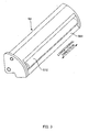
- the vertical direction is indicated by arrows, and for example the central shaft of the developing roller 510 is in a lower position than the central shaft of the photoconductor 20.
- the yellow developing device 54 is shown positioned at the developing position, which is in opposition to the photoconductor 20.
- the projection sections 512 and the like are not to scale in order to make the diagrams easier to understand.
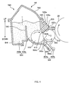
- the longitudinal direction and the lateral direction of the regulation blade 560 in FIG. 8 and the lateral direction and the thickness direction of the regulation blade 560 in FIG. 9 are shown with arrows respectively.
- the regulation blade 560 comes into contact with the developing roller 510 at a contact section 560a so that the longitudinal direction of the regulation blade 560 runs along the rotation-axis direction of the developing roller 510 from one end portion to the other end portion in the rotation-axis direction of the developing roller 510, and regulates the amount of the toner T borne on the developing roller 510 (the projection sections 512 and the non-projection sections 513), and moreover, it applies a charge to the toner T borne on the developing roller 510.
- the distance g corresponds to a length of the virtual line from the leading edge 560b to where it intersects the projection sections 512). More specifically, the distance g is approximately 2 ⁇ m, which is a value smaller than the volume mean particle size of the toner T (approximately 4.6 ⁇ m).
- an end portion seal 574 is provided on a longitudinal direction outer side of the regulation blade 560.
- the end portion seal 574 is made up of a nonwoven fabric, and contacts the developing roller 510 along the circumferential surface thereof at the end portion in the rotation-axis direction thereof, so as to perform a function to prevent leakage of the toner T from a space between the circumferential surface and the housing 540.
- the upper seal 520 is supported by the upper seal support section 526a at a lateral direction end portion 520a thereof ( FIG. 4 ), and the developing roller 510 is supported by the developing roller support sections 526b at its ends.
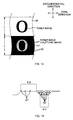
- FIG. 13 shows a toner image expressing the alphabet letter "O" formed on the photoconductor 20 by executing the aforementioned series of processes in the n-th revolution of the developing roller 510, and a halftone image formed on the photoconductor 20 by executing the aforementioned series of processes in the (n + 1)-th revolution of the developing roller 510.
- the toner images formed on the photoconductor 20 are shown on the circumferential surface of the photoconductor 20, which is schematically extended, and the circumferential direction and the axial direction of the photoconductor 20 are indicated with arrows.
- the length L indicated in FIG. 13 corresponds to a length of one revolution of the circumferential surface of the developing roller 510.
- FIG. 13 shows a condition in which the density of the halftone image formed by developing the latent image facing the first region (indicated in FIG. 13 with the reference symbol A1) is lighter than the density of the halftone image formed by developing the latent image facing the second region (indicated in FIG. 13 with the reference symbol A2). Also, since the first region is shaped as the letter "O" as mentioned earlier, the lighter density halftone image that is formed by developing the latent image facing the first region is also shaped as the letter "O".
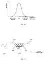
- a 3 ⁇ value namely a value obtained by subtracting 3 times a standard deviation ⁇ in the toner particle size distribution from the volume mean particle size Ave (hereinafter referred to as a "minus 3 ⁇ value” for the sake of convenience)
- a value obtained by adding 3 times the standard deviation ⁇ in the toner particle size distribution to the volume mean particle size (hereinafter referred to as a "plus 3 ⁇ value” for the sake of convenience) are approximately 2.3 ⁇ m and approximately 6.9 ⁇ m respectively.
- the toner used in the printer 10 according to the present embodiment does not contain a charge control agent (CCA).
- CCA charge control agent
- a coloring toner particle having a desired particle size can be formed by adding while agitating a monomer composite, in which a polymerizable monomer, a coloring agent (coloring pigment), a release agent, and further as required, a dye, a polymerization initiator, a cross-linking agent, and other additives have been dissolved or dispersed, to an aqueous phase containing a suspension stabilizer (a water-soluble macromolecule and a poorly water-soluble inorganic substance), then causing granulation and polymerization.
- a suspension stabilizer a water-soluble macromolecule and a poorly water-soluble inorganic substance
- the external additive becomes externally added to the coloring toner particle, and thus obtaining a cyan toner having a volume mean particle size of 4.6 ⁇ m.
- the toner electrical-charge buildup becomes slower. Furthermore, since the toner does not contain a charge control agent (CCA), charge control for increasing the speed of the toner electrical-charge buildup cannot be implemented. Furthermore, the toner electrical-charge buildup will be slow regardless since there is a large amount of coloring agent (coloring pigment).
- CCA charge control agent
- the toner electrical-charge buildup is slow, and therefore development memory tends to occur easily.
- the toner volume mean particle size (approximately 4.6 ⁇ m) is smaller than the depth d of the depressed sections 515 (approximately 8 ⁇ m), and therefore the toner that is borne in the depressed sections 515 and has this volume mean particle size is able to pass through the (2 ⁇ m) gap between the leading edge 560b and the opposing area 512a and reaches the developing position opposing the photoconductor 20.
- the depressed section covering ratio is a parameter (a parameter indicating the degree to which the toner covers the depressed sections 515) obtained on the assumption that the toner that covers the depressed sections 515 is the toner that contacts the depressed sections 515 only, in other words, that toner that does not contact the depressed sections 515 is not present.
- FIG. 14 is a diagram illustrating a state of toner borne on the projection sections 512 and the depressed sections 515 at the developing position.
- FIG. 14 shows a state in which only the toner having an extremely small particle size that could have passed through the (2 ⁇ m) gap between the leading edge 560b and the opposing area 512a is borne on the projection sections 512.
- toner contained in the toner container 530 is freshly supplied in the process of charging and supplying toner using the toner supply roller 550 in the (n + 1) -th revolution.
- the toner freshly supplied to the first region is toner having a property of being a toner whose electrical-charge buildup is slow, the toner will not be borne appropriately in the first region of the developing roller 510 during frictional charging carried out by the toner supply roller 550 and the developing roller 510.
- a difference between the density of the halftone image formed by developing the latent image facing the depressed sections 515 of the first region and the density of the halftone image formed by developing the latent image facing the depressed sections 515 of the second region is smaller than a difference between the density of the halftone image formed by developing the latent image facing the projection sections 512 of the first region and the density of the halftone image formed by developing the latent image facing the projection sections 512 of the second region.
- the projection sections 512 and the depressed sections 515 are formed so that the depth d of the depressed sections 515 is uniform between all the depressed sections 515 provided in the developing roller 510. Therefore, the toner borne in the depressed sections 515 can pass through the (2 ⁇ m) gap between the leading edge 560b and the opposing area 512a. Accordingly, this embodiment can further inhibit occurrences of development memory.
- the projection sections 512 have flat top surfaces, and the projection sections 512 are appropriately prevented from being worn (ground down) due to the load of the regulation blade 560.
- the developing roller 510 provided in the developing devices 51, 52, 53, and 54 according to the present embodiment includes the regularly arranged projection sections 512 on the surface thereof.
- the ten-point average roughness Rz of the projection sections 512 is smaller than the value obtained by subtracting 3 times a standard deviation ⁇ in the particle size distribution of a toner from the volume mean particle size Ave of the toner (namely, minus 3 ⁇ value) .
- a difference between the density of the halftone image formed by developing the latent image facing the depressed sections 515 of the first region and the density of the halftone image formed by developing the latent image facing the depressed sections 515 of the second region is smaller than a difference between the density of the halftone image formed by developing the latent image facing the projection sections 512 of the first region and the density of the halftone image formed by developing the latent image facing the projection sections 512 of the second region.
- the ten-point average roughness Rz of the depressed sections 515 (approximately 0.7 ⁇ m) is also smaller than the minus 3 ⁇ value and toner whose particle size is smaller than the minus 3 ⁇ value can be borne in the depressed sections 515.
- the depressed sections 515 do not bear only toner whose particle size is smaller than the minus 3 ⁇ value, and the depressed sections 515 also bear toner having the volume mean particle size (approximately 4.6 ⁇ m). This is because the non-projection sections 513 are cupped so as to easily accommodate toner, and the toner having the volume mean particle size is borne in the depressed sections 515 with an aggregation force generated when toner is packed in the non-projection sections 513.
- the aggregation force acts on the toner borne in the depressed sections 515, and therefore it is difficult for the toner to separate from the depressed sections 515 during rotation of the developing roller 510, and the toner remains to be borne in the depressed sections 515. As a result, a larger amount of toner (mainly the toner having the volume mean particle size) is borne in the depressed sections 515 than on the projection sections 512.
- the regulating state of the regulation blade 560 is set so that, as shown in FIG. 9 , the distance g (approximately 2 ⁇ m) from the leading edge 560b to the projection sections 512 in the case where the leading edge 560b faces the projection sections 512 of the rotating developing roller 510, is extremely small. Specifically, the distance g is smaller than the minus 3 ⁇ value (approximately 2.3 ⁇ m), obtained by subtracting 3 times a standard deviation ⁇ in the toner particle size distribution from the volume mean particle size Ave of toner. In this way, as described above, occurrences of the aforementioned development memory can be effectively inhibited.
- the toner that has been borne on the projection sections 512 by the toner supply roller 550 has reached the regulation blade 560, the toner that is borne on the projection sections 512 having a particle size greater than 2 ⁇ m (almost all toner) is unable to pass through the (2 ⁇ m) gap between the leading edge 560b and the opposing area 512a (it rebounds upon hitting the leading edge 560b), and cannot reach the developing position opposing the photoconductor 20.
- the depth d of the depressed sections 515 (approximately 8 ⁇ m) is greater than plus 3 ⁇ value (approximately 6.9 ⁇ m), and therefore the toner that is borne in the depressed sections 515 is able to pass through the (2 ⁇ m) gap between the leading edge 560b and the opposing area 512a and reaches the developing position opposing the photoconductor 20.
- a larger amount of toner (mainly the toner having the volume mean particle size) is borne in the depressed sections 515 than by the projection sections 512.
- occurrences of development memory can be effectively inhibited.
- FIG. 17 is a schematic diagram for describing effectiveness of the developing devices 51, 52, 53, and 54 according to the present embodiment. That is, FIG. 17 shows a state of the toner borne on the projection sections 512 and the depressed sections 515 (the non-projection sections 513) at the developing position in the case where the ten-point average roughness Rz of the projection sections 512 is smaller than the minus 3 ⁇ value, and also the distance g is smaller than the minus 3 ⁇ value.
- the latent image borne on the photoconductor 20 is mostly developed using the toner borne on the depressed sections 515 (including toner borne on the lateral sections 514), and therefore occurrences of development memory can be more effectively inhibited.
- the method for manufacturing the developing roller 510 is described first, and thereafter the method for assembling the developing device is described.
- the yellow developing device 54 is taken as an example from among the black developing device 51, the magenta developing device 52, the cyan developing device 53, and the yellow developing device 54.
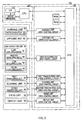
- the method for manufacturing the developing roller 510 is described with reference to FIGS. 18A to FIG. 19 .
- a pipe member 600 is prepared, which is used as the base member of the developing roller 510.
- the wall thickness of this pipe member 600 is 0.5 to 3 mm.
- flange press-fitting sections 602 are formed at the both ends in the longitudinal direction of the pipe member 600.
- the flange press-fitting sections 602 are made by a cutting process.
- a flange 604 is injected to the flange press-fitting sections 602.
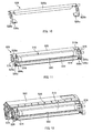
- the two round dies 650, 652 arranged so that they sandwich the pipe member 600 serving as the workpiece are rotated in the same direction (see FIG. 19 ) while being pressed with a predetermined pressure (the direction of this pressure is marked with the reference symbol P in FIG. 19 ) against the pipe member 600.
- the pipe member 600 moves in the direction indicated by the reference symbol H in FIG. 19 while rotating in the direction opposite to the rotating direction of the round dies 650 and 652 (see FIG. 19 ).
- Convex sections 650a and 652a for forming a groove 680 are provided respectively on the surface of the round dies 650 and 652.
- the convex sections 650a and 652a deform the pipe member 600 to form the groove 680 on the pipe member 600 (here the groove 680 corresponds to the first groove portion 516 and the second groove portion 518).
- plating is performed on the surface of the central area 510a.
- electroless Ni-P plating is employed.
- hard chrome plating or electroplating may be employed for example.
- the projection sections 512 and the depressed sections 515 of the developing roller 510 manufactured in this manner are rough, and the ten-point average roughness Rz of the projection sections 512 and the ten-point average roughness Rz of the depressed sections 515 are approximately 0.3 ⁇ m and approximately 0.7 ⁇ m, respectively.
- the projection sections 512 and the depressed sections 515 are rough because the projection sections 512 and the depressed sections 515 are scratched (small grooves are formed) during centerless grinding or the rolling process.
- the projection sections 512 and the depressed sections 515 formed by the convex sections 650a and 652a are also rough.
- step S4 the regulation blade 560 and the blade support member 564 are secured to the holder 526 as a result of the regulation blade 560 and the blade support member 564 being fixed to the regulation blade support sections 526c of the holder 526 with screws. It should be noted that the aforementioned end portion seal 574 is attached to the regulation blade 560 ahead of this step S4.
- step S8 the holder 526 to which the developing roller 510, regulation blade 560 and the like have been attached, is attached to the housing 540 via the housing seal 546 (step S8), thereby completing assembly of the yellow developing device 54.
- the aforementioned toner supply roller 550 is attached to the housing 540 ahead of this step S8.
- an intermediate transfer type full-color laser beam printer was described as an example of the image forming apparatus, but the invention can also be applied to various other types of image forming apparatuses, such as full-color laser beam printers that are not of the intermediate transfer type, monochrome laser beam printers, copying machines, and facsimile machines.
- the photoconductor is not limited to a so-called photosensitive roller, which is configured by providing a photoconductive layer on the outer circumferential surface of a hollow cylindrical conductive base, and can also be a so-called photosensitive belt, which is configured by providing a photoconductive layer on the surface of a belt-shaped conductive base.
- the shape of the projection sections 512 and the non-projection sections 513 of the developing roller 510 is not limited to the shape described above.
- the amount of toner borne on the developing roller 510 may be regulated by the regulation blade 560 whose contact section 560a is roughened (during processing). In this manner, the protruded portions in the roughened contact section 560a flick away a part of toner borne on the projection sections 512, so the projection section covering ratio can be made smaller than the depressed section covering ratio.
- the contact section 560a is positioned at a position separated from the leading edge 560b. That is, a configuration was adopted in which the leading edge 560b does not contact the developing roller 510.
- the leading edge 560b may contact the developing roller 510 (in such a case, the manner of regulation by the regulation blade 560 will be regulation by the leading edge of the blade, and the distance g from the leading edge 560b to the projection sections 512 in the case where the leading edge 560b faces the projection sections 512 of the rotating developing roller 510 will be 0) .
- the toner used in the printer 10 according to the above embodiment has properties described in the paragraphs 1) to 4). However, there is no limitation to this. It is not required to have these properties.
- the plus 3 ⁇ value is smaller than the depth d of the depressed sections 515.
- the plus 3 ⁇ value may be larger than the depth d of the depressed sections 515.
- the projection sections 512 and the depressed sections 515 that bear toner are disposed in a regular manner on the surface of the developing roller 510, and the ten-point average roughness Rz of the depressed sections 515 (approximately 0.7 ⁇ m) is larger than the ten-point average roughness Rz of the projection sections 512 (approximately 0.3 ⁇ m).
- the ten-point average roughness Rz of the depressed sections 515 may be smaller than the ten-point average roughness Rz of the projection sections 512.
- the charging amount of the toner increases as a result of the toner contacting the depressed sections 515 rolling, which makes it easier for the toner to remain in the depressed sections 515.
- discharge between the depressed sections 515 and the photoconductor 20 that have just passed the developing position can be suppressed.
- the above-described embodiment is more preferable.
- the depressed sections 515 were bottom portions of two types of spiral groove portions (that is, the first groove portion 516 and the second groove portion 518) having different inclination angles with respect to the circumferential direction of the developing roller 510, and the two types of spiral groove portions mutually intersected so as to form a grid pattern.
- the projection sections 512 were square top surfaces surrounded by the two types of spiral groove portions, and one of two diagonal lines of the square top surface ran along the circumferential direction of the developing roller 510.
- the projection sections 512 may be rhomboid top surfaces or circular top surfaces or the like.
- FIG. 21 is an explanatory diagram showing an external configuration of an image forming system.
- An image forming system 700 is provided with a computer 702, a display device 704, a printer 706, input devices 708, and reading devices 710.
- the computer 702 is contained within a mini-tower type housing, but there is no limitation to these.
- a CRT (cathode ray tube) , plasma display, or liquid crystal display device, for example, is generally used as the display device 704, but there is no limitation to this.
- the printer described above is used as the printer 706.
- the input devices 708 are a keyboard 708A and a mouse 708B, but there is no limitation to these.
- a flexible disk drive device 710A and a CD-ROM drive device 710B are used as the reading device 710, but the reading device 710 is not limited to these, and it may also be an MO (magnet optical) disk drive device or a DVD (digital versatile disk), for example.
- MO magnet optical
- DVD digital versatile disk
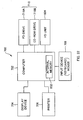
- FIG. 22 is a block diagram showing the configuration of the image forming system shown in FIG. 21 .
- An internal memory 802 such as a RAM is provided within the casing containing the computer 702, and furthermore an external memory such as a hard disk drive unit 804 is provided.
- the image forming system is constituted by connecting the printer 706 to the computer 702, the display device 704, the input devices 708, and the reading devices 710, but there is no limitation to this.
- the image forming system may also be made of the computer 702 and the printer 706, and the image forming system does not have to be provided with any one of the display device 704, the input devices 708, and the reading devices 710.
- the printer 706 for example has some of the functions or mechanisms of the computer 702, the display device 704, the input devices 708, and the reading devices 710.
- the printer 706 may be configured so as to have an image processing section for carrying out image processing, a display section for carrying out various types of displays, and a recording media mount/dismount section into and from which recording media storing image data captured by a digital camera or the like are inserted and taken out.
Landscapes
- Physics & Mathematics (AREA)
- General Physics & Mathematics (AREA)
- Dry Development In Electrophotography (AREA)
Applications Claiming Priority (3)
| Application Number | Priority Date | Filing Date | Title |
|---|---|---|---|
| JP2007144062A JP4853384B2 (ja) | 2007-05-30 | 2007-05-30 | 現像装置、画像形成装置、及び、画像形成システム |
| JP2007144065A JP5125226B2 (ja) | 2007-05-30 | 2007-05-30 | 現像装置、画像形成装置、及び、画像形成システム |
| JP2007144061A JP2008299011A (ja) | 2007-05-30 | 2007-05-30 | 現像装置、画像形成装置、画像形成システム、及び、現像方法 |
Publications (2)
| Publication Number | Publication Date |
|---|---|
| EP2028562A2 true EP2028562A2 (fr) | 2009-02-25 |
| EP2028562A3 EP2028562A3 (fr) | 2016-01-13 |
Family
ID=40088370
Family Applications (1)
| Application Number | Title | Priority Date | Filing Date |
|---|---|---|---|
| EP08009799.1A Withdrawn EP2028562A3 (fr) | 2007-05-30 | 2008-05-29 | Dispositif de développement, appareil de formation d'image, système de formation d'image, procédé de développement, et élément de revêtement de toner |
Country Status (2)
| Country | Link |
|---|---|
| US (1) | US8086152B2 (fr) |
| EP (1) | EP2028562A3 (fr) |
Cited By (1)
| Publication number | Priority date | Publication date | Assignee | Title |
|---|---|---|---|---|
| EP2053469A1 (fr) * | 2007-10-26 | 2009-04-29 | Seiko Epson Corporation | Appareil de développeur, appareil de formation d'images et procédé de développement |
Families Citing this family (9)
| Publication number | Priority date | Publication date | Assignee | Title |
|---|---|---|---|---|
| US7925192B2 (en) * | 2007-09-04 | 2011-04-12 | Ricoh Company, Ltd. | Developing roller, developing device, process cartridge, and image forming apparatus |
| US8032064B2 (en) * | 2007-10-26 | 2011-10-04 | Seiko Epson Corporation | Developer apparatus, image forming apparatus and developing method |
| JP4596012B2 (ja) * | 2008-01-23 | 2010-12-08 | セイコーエプソン株式会社 | 現像装置、画像形成装置および画像形成方法 |
| EP2093628A2 (fr) * | 2008-02-20 | 2009-08-26 | Seiko Epson Corporation | Rouleau de développement, dispositif de développement et appareil de formation d'images |
| EP2093629A3 (fr) * | 2008-02-20 | 2010-03-10 | Seiko Epson Corporation | Rouleau de développement, dispositif de développement et appareil de formation d'images |
| JP2010224183A (ja) * | 2009-03-23 | 2010-10-07 | Seiko Epson Corp | 現像装置、画像形成装置および画像形成方法 |
| JP2010224182A (ja) * | 2009-03-23 | 2010-10-07 | Seiko Epson Corp | 現像装置、画像形成装置および画像形成方法 |
| US9201336B2 (en) * | 2012-02-13 | 2015-12-01 | Ricoh Company, Ltd. | Developing device and image forming apparatus including a toner bearing member having a predetermined relationship with toner |
| JP2016080982A (ja) * | 2014-10-21 | 2016-05-16 | 富士ゼロックス株式会社 | 画像形成装置 |
Citations (5)
| Publication number | Priority date | Publication date | Assignee | Title |
|---|---|---|---|---|
| JP2003057940A (ja) | 2001-08-09 | 2003-02-28 | Ricoh Co Ltd | 現像装置、現像方法、画像形成装置及び現像剤 |
| JP2006259384A (ja) | 2005-03-17 | 2006-09-28 | Seiko Epson Corp | 現像装置および画像形成装置 |
| JP2007144062A (ja) | 2005-11-30 | 2007-06-14 | Nippon Zeon Co Ltd | 医療用器具及びその製造方法 |
| JP2007144061A (ja) | 2005-11-30 | 2007-06-14 | Olympia:Kk | 遊技機の入賞装置 |
| JP2007144065A (ja) | 2005-11-30 | 2007-06-14 | Kitamura Seisakusho:Kk | グラフト、及び内装補強材の装着装置 |
Family Cites Families (65)
| Publication number | Priority date | Publication date | Assignee | Title |
|---|---|---|---|---|
| US4092165A (en) | 1975-05-05 | 1978-05-30 | Xerox Corporation | Method of making a donor member mold |
| JPS5526526A (en) | 1978-08-15 | 1980-02-26 | Hitachi Metals Ltd | Magnet roll |
| JPS5764764A (en) | 1980-10-09 | 1982-04-20 | Canon Inc | Dry type development device |
| JPH0614219B2 (ja) | 1983-04-12 | 1994-02-23 | キヤノン株式会社 | 現像方法 |
| JPS61147264A (ja) | 1984-12-21 | 1986-07-04 | Kyocera Corp | トナ−層形成方法及びその装置 |
| US4780741A (en) | 1985-02-19 | 1988-10-25 | Kyocera Corporation | Method and apparatus for forming toner layer |
| US4978583A (en) | 1986-12-25 | 1990-12-18 | Kawasaki Steel Corporation | Patterned metal plate and production thereof |
| JP2601275B2 (ja) | 1987-06-05 | 1997-04-16 | 京セラ株式会社 | 電子写真現像装置 |
| JP2537249B2 (ja) | 1987-10-15 | 1996-09-25 | キヤノン株式会社 | 現像剤担持体 |
| JP2851002B2 (ja) | 1989-03-09 | 1999-01-27 | 三田工業株式会社 | 磁気ブラシ現像装置の現像スリーブ |
| JPH04295871A (ja) | 1991-03-26 | 1992-10-20 | Matsushita Electric Ind Co Ltd | 一成分磁性トナー現像装置 |
| JP2815493B2 (ja) | 1991-03-29 | 1998-10-27 | トーカロ株式会社 | めっき浴用ロール |
| JPH0525459A (ja) | 1991-07-22 | 1993-02-02 | Mitsui Toatsu Chem Inc | ホツトメルト目地材とその充填加工方法 |
| JP3363916B2 (ja) | 1991-11-20 | 2003-01-08 | 株式会社リコー | 湿式現像装置 |
| US5339141A (en) | 1992-02-16 | 1994-08-16 | Ricoh Company, Ltd. | Developing device with a developer carrier capable of forming numerous microfields thereon |
| US5387966A (en) | 1992-05-22 | 1995-02-07 | Ricoh Company, Ltd. | Developing apparatus and method including grooved developer carrying roller |
| JPH06124043A (ja) | 1992-08-31 | 1994-05-06 | Toshiba Corp | 電子写真装置用の現像装置およびトナー |
| JPH06138774A (ja) | 1992-10-27 | 1994-05-20 | Fuji Xerox Co Ltd | 現像装置 |
| JPH0713410A (ja) | 1993-06-19 | 1995-01-17 | Ricoh Co Ltd | 現像装置 |
| JPH08160736A (ja) | 1994-12-07 | 1996-06-21 | Canon Inc | 現像スリーブ及び現像装置 |
| US5552235A (en) | 1995-03-23 | 1996-09-03 | Bethlehem Steel Corporation | Embossed cold rolled steel with improved corrosion resistance, paintability, and appearance |
| JP3200325B2 (ja) | 1995-04-12 | 2001-08-20 | シャープ株式会社 | 現像装置 |
| JPH08286497A (ja) | 1995-04-15 | 1996-11-01 | Ricoh Co Ltd | トナー担持体及びその製造方法 |
| DE19515393B4 (de) | 1995-04-26 | 2004-01-15 | Man Roland Druckmaschinen Ag | Bedruckstofführende Oberflächenstruktur, vorzugsweise für Druckmaschinenzylinder oder deren Aufzüge |
| JPH08328376A (ja) | 1995-06-01 | 1996-12-13 | Canon Inc | 画像形成装置用円筒部材およびその製造方法 |
| JPH09197800A (ja) | 1996-01-18 | 1997-07-31 | Ricoh Co Ltd | 画像形成装置の現像ローラ |
| JPH1020662A (ja) | 1996-06-28 | 1998-01-23 | Ricoh Co Ltd | 現像装置 |
| JP3624926B2 (ja) | 1997-01-23 | 2005-03-02 | セイコーエプソン株式会社 | 画像形成装置 |
| US6317220B1 (en) | 1996-12-06 | 2001-11-13 | Seiko Epson Corporation | Image forming apparatus capable of preventing linear nonuniformity and improving image quality |
| JP3800774B2 (ja) | 1997-12-09 | 2006-07-26 | 株式会社カネカ | 表面に海島構造を有する現像ローラ |
| KR100356916B1 (ko) | 1997-07-01 | 2002-10-18 | 가네가후치 가가쿠고교 가부시키가이샤 | 현상롤러 및 이 롤러를 이용한 현상장치 |
| JPH11133728A (ja) | 1997-10-27 | 1999-05-21 | Canon Inc | 現像剤担持体及び現像装置 |
| DE69921552T2 (de) | 1998-06-24 | 2006-01-05 | Canon K.K. | Toner und Bildherstellungsverfahren |
| JP2000242073A (ja) | 1999-02-19 | 2000-09-08 | Konica Corp | 現像装置 |
| JP2000258989A (ja) | 1999-03-09 | 2000-09-22 | Fuji Xerox Co Ltd | 現像装置 |
| JP4161241B2 (ja) | 1999-03-25 | 2008-10-08 | ブラザー工業株式会社 | 現像方法 |
| JP3588563B2 (ja) | 1999-03-31 | 2004-11-10 | キヤノン株式会社 | 現像剤担持部材、それを用いた現像装置及び画像形成装置 |
| JP3506977B2 (ja) | 1999-11-05 | 2004-03-15 | シャープ株式会社 | 現像ローラ及びこの現像ローラを備えた現像装置 |
| JP2002112224A (ja) | 2000-09-29 | 2002-04-12 | Just Syst Corp | 放送番組リンク情報提供システム、装置、方法及び記録媒体 |
| JP2002372855A (ja) | 2001-04-13 | 2002-12-26 | Canon Chemicals Inc | 現像剤量規制ブレード、現像装置、現像剤量規制ブレードの製造方法 |
| JP3997065B2 (ja) | 2001-08-20 | 2007-10-24 | キヤノン株式会社 | プロセスカートリッジ及び画像形成装置 |
| JP2003107905A (ja) | 2001-09-27 | 2003-04-11 | Seiko Epson Corp | 現像装置、画像形成装置、トナー、及び、コンピュータシステム |
| JP2003208012A (ja) | 2002-01-11 | 2003-07-25 | Ricoh Co Ltd | 画像形成装置 |
| US6941100B2 (en) | 2002-03-07 | 2005-09-06 | Seiko Epson Corporation | Developer bearing member, method for producing developer bearing member, developing device, image-forming apparatus, and computer system |
| JP2003263018A (ja) | 2002-03-07 | 2003-09-19 | Seiko Epson Corp | 現像剤担持体、現像剤担持体製造方法、現像装置、画像形成装置、及び、コンピュータシステム |
| JP2003316146A (ja) | 2002-04-24 | 2003-11-06 | Fuji Xerox Co Ltd | 現像剤担持体 |
| EP1372045B1 (fr) | 2002-06-12 | 2009-09-02 | Ricoh Company, Ltd. | Dispositif de développement avec rainures et appareil de formation d'images l'utilisant |
| JP2004020581A (ja) | 2002-06-12 | 2004-01-22 | Ricoh Co Ltd | 現像装置、現像剤担持体、画像形成方法及び装置 |
| JP2004034537A (ja) | 2002-07-04 | 2004-02-05 | Canon Chemicals Inc | トナー搬送ローラ成形型およびその製造方法 |
| JP2004212520A (ja) | 2002-12-27 | 2004-07-29 | Canon Inc | トナー及び画像形成方法 |
| JP2005049649A (ja) | 2003-07-29 | 2005-02-24 | Canon Inc | トナー |
| FI116076B (fi) | 2004-02-10 | 2005-09-15 | Metso Paper Inc | Uritettu rainanmuodostustela |
| US7330684B2 (en) | 2004-09-14 | 2008-02-12 | Seiko Epson Corporation | Developing device, image forming apparatus, image forming system, charging member, and method for manufacturing developing device |
| US7149459B2 (en) | 2004-11-10 | 2006-12-12 | Seiko Epson Corporation | Application roller and image forming apparatus |
| US20060111223A1 (en) | 2004-11-23 | 2006-05-25 | Chih-Huang Chou | Etched type inkjet printer roller |
| JP4715319B2 (ja) | 2005-06-09 | 2011-07-06 | パナソニック株式会社 | マグネットロール |
| JP2007121974A (ja) | 2005-10-24 | 2007-05-17 | Kenichi Kobayashi | 表面に摩滅防止用の皮膜層(1)をもうけた、大型文字等の印刷物(2)の下面に、非接着体の表面形状に応じて任意に変形する簡易変形素材(3)を圧着し、さらにその簡易変形素材(3)の下面に非接着体への密着を目的とする接着剤(4)を有する構造からなる、シ−ル形状物。 |
| JP4692223B2 (ja) | 2005-10-31 | 2011-06-01 | セイコーエプソン株式会社 | 現像装置、トナー粒子担持ローラ、画像形成装置、画像形成システム、及び、トナー粒子担持ローラの製造方法 |
| US7565099B2 (en) * | 2005-10-31 | 2009-07-21 | Seiko Epson Corporation | Developing device and image forming apparatus having a toner-particle bearing roller with a helical groove portion |
| JP4765555B2 (ja) | 2005-10-31 | 2011-09-07 | セイコーエプソン株式会社 | 現像装置、画像形成装置、画像形成システム、及び、現像装置の製造方法 |
| CN102004417A (zh) | 2005-11-02 | 2011-04-06 | 精工爱普生株式会社 | 调色剂颗粒承载辊、以及显影装置 |
| JP4821271B2 (ja) | 2005-11-02 | 2011-11-24 | セイコーエプソン株式会社 | 現像装置、トナー粒子担持ローラ、画像形成装置、画像形成システム、及び、トナー粒子担持ローラの製造方法 |
| JP4715451B2 (ja) | 2005-11-02 | 2011-07-06 | セイコーエプソン株式会社 | 現像装置、トナー粒子担持ローラ、画像形成装置、画像形成システム、及び、トナー粒子担持ローラの製造方法 |
| JP2008299014A (ja) * | 2007-05-30 | 2008-12-11 | Seiko Epson Corp | 画像形成装置、及び、画像形成システム |
| JP4862748B2 (ja) * | 2007-05-30 | 2012-01-25 | セイコーエプソン株式会社 | 現像装置、画像形成装置、及び、画像形成システム |
-
2008
- 2008-05-21 US US12/124,939 patent/US8086152B2/en not_active Expired - Fee Related
- 2008-05-29 EP EP08009799.1A patent/EP2028562A3/fr not_active Withdrawn
Patent Citations (5)
| Publication number | Priority date | Publication date | Assignee | Title |
|---|---|---|---|---|
| JP2003057940A (ja) | 2001-08-09 | 2003-02-28 | Ricoh Co Ltd | 現像装置、現像方法、画像形成装置及び現像剤 |
| JP2006259384A (ja) | 2005-03-17 | 2006-09-28 | Seiko Epson Corp | 現像装置および画像形成装置 |
| JP2007144062A (ja) | 2005-11-30 | 2007-06-14 | Nippon Zeon Co Ltd | 医療用器具及びその製造方法 |
| JP2007144061A (ja) | 2005-11-30 | 2007-06-14 | Olympia:Kk | 遊技機の入賞装置 |
| JP2007144065A (ja) | 2005-11-30 | 2007-06-14 | Kitamura Seisakusho:Kk | グラフト、及び内装補強材の装着装置 |
Cited By (1)
| Publication number | Priority date | Publication date | Assignee | Title |
|---|---|---|---|---|
| EP2053469A1 (fr) * | 2007-10-26 | 2009-04-29 | Seiko Epson Corporation | Appareil de développeur, appareil de formation d'images et procédé de développement |
Also Published As
| Publication number | Publication date |
|---|---|
| US8086152B2 (en) | 2011-12-27 |
| US20080298853A1 (en) | 2008-12-04 |
| EP2028562A3 (fr) | 2016-01-13 |
Similar Documents
| Publication | Publication Date | Title |
|---|---|---|
| US8086152B2 (en) | Developing device, image forming apparatus, image forming system, developing method, and toner bearing member | |
| EP1998228B1 (fr) | Dispositif de développement, appareil de formation d'image, et système de formation d'image | |
| US8401443B2 (en) | Toner-particle bearing roller, developing device, and image forming apparatus | |
| US7729647B2 (en) | Image forming apparatus, image forming method, and image forming system | |
| US7751760B2 (en) | Image forming apparatus, image forming method, and image forming system | |
| JP2008299014A (ja) | 画像形成装置、及び、画像形成システム | |
| JP5061729B2 (ja) | 現像装置、画像形成装置、及び、画像形成システム | |
| US7330684B2 (en) | Developing device, image forming apparatus, image forming system, charging member, and method for manufacturing developing device | |
| US5621505A (en) | Developing apparatus having rotatable developer supply member for developer carrying member | |
| CN101329535B (zh) | 显影设备、图像形成装置和图像形成系统 | |
| JP4692226B2 (ja) | 現像装置、画像形成装置、及び、画像形成システム | |
| JP4784704B2 (ja) | 現像剤担持ローラ、現像装置、画像形成装置、及び、画像形成システム | |
| JP5125226B2 (ja) | 現像装置、画像形成装置、及び、画像形成システム | |
| JP4853384B2 (ja) | 現像装置、画像形成装置、及び、画像形成システム | |
| JP5076357B2 (ja) | 現像剤規制部材、及び、現像装置 | |
| US20080025765A1 (en) | Toner-regulating roller having specific surface elastic force, developing apparatus and developing method using the same | |
| JP4784703B2 (ja) | 現像剤担持ローラ、現像装置、画像形成装置、及び、画像形成システム | |
| JP2008096870A (ja) | 現像ローラ | |
| JP2009151084A (ja) | 現像装置及びプロセスカートリッジ | |
| JP2007133243A (ja) | 現像剤担持ローラ、現像装置、画像形成装置、及び、画像形成システム |
Legal Events
| Date | Code | Title | Description |
|---|---|---|---|
| PUAI | Public reference made under article 153(3) epc to a published international application that has entered the european phase |
Free format text: ORIGINAL CODE: 0009012 |
|
| AK | Designated contracting states |
Kind code of ref document: A2 Designated state(s): AT BE BG CH CY CZ DE DK EE ES FI FR GB GR HR HU IE IS IT LI LT LU LV MC MT NL NO PL PT RO SE SI SK TR |
|
| AX | Request for extension of the european patent |
Extension state: AL BA MK RS |
|
| PUAL | Search report despatched |
Free format text: ORIGINAL CODE: 0009013 |
|
| AK | Designated contracting states |
Kind code of ref document: A3 Designated state(s): AT BE BG CH CY CZ DE DK EE ES FI FR GB GR HR HU IE IS IT LI LT LU LV MC MT NL NO PL PT RO SE SI SK TR |
|
| AX | Request for extension of the european patent |
Extension state: AL BA MK RS |
|
| RIC1 | Information provided on ipc code assigned before grant |
Ipc: G03G 15/08 20060101AFI20151210BHEP |
|
| AKY | No designation fees paid | ||
| AXX | Extension fees paid |
Extension state: AL Extension state: MK Extension state: BA Extension state: RS |
|
| REG | Reference to a national code |
Ref country code: DE Ref legal event code: R108 |
|
| STAA | Information on the status of an ep patent application or granted ep patent |
Free format text: STATUS: THE APPLICATION IS DEEMED TO BE WITHDRAWN |
|
| 18D | Application deemed to be withdrawn |
Effective date: 20160714 |