EP2028571A2 - Verfahren zur Erkennung von Verbindungsunterbrechungen und Stromlecks in einer mit einem numerischen Kontrollgerät verbundenen I/O-Einheit - Google Patents
Verfahren zur Erkennung von Verbindungsunterbrechungen und Stromlecks in einer mit einem numerischen Kontrollgerät verbundenen I/O-Einheit Download PDFInfo
- Publication number
- EP2028571A2 EP2028571A2 EP08160124A EP08160124A EP2028571A2 EP 2028571 A2 EP2028571 A2 EP 2028571A2 EP 08160124 A EP08160124 A EP 08160124A EP 08160124 A EP08160124 A EP 08160124A EP 2028571 A2 EP2028571 A2 EP 2028571A2
- Authority
- EP
- European Patent Office
- Prior art keywords
- unit
- power discontinuity
- units
- communication
- power
- Prior art date
- Legal status (The legal status is an assumption and is not a legal conclusion. Google has not performed a legal analysis and makes no representation as to the accuracy of the status listed.)
- Granted
Links
Images




Classifications
-
- G—PHYSICS
- G05—CONTROLLING; REGULATING
- G05B—CONTROL OR REGULATING SYSTEMS IN GENERAL; FUNCTIONAL ELEMENTS OF SUCH SYSTEMS; MONITORING OR TESTING ARRANGEMENTS FOR SUCH SYSTEMS OR ELEMENTS
- G05B19/00—Program-control systems
- G05B19/02—Program-control systems electric
- G05B19/04—Program control other than numerical control, i.e. in sequence controllers or logic controllers
- G05B19/042—Program control other than numerical control, i.e. in sequence controllers or logic controllers using digital processors
- G05B19/0423—Input/output
- G05B19/0425—Safety, monitoring
-
- G—PHYSICS
- G05—CONTROLLING; REGULATING
- G05B—CONTROL OR REGULATING SYSTEMS IN GENERAL; FUNCTIONAL ELEMENTS OF SUCH SYSTEMS; MONITORING OR TESTING ARRANGEMENTS FOR SUCH SYSTEMS OR ELEMENTS
- G05B19/00—Program-control systems
- G05B19/02—Program-control systems electric
- G05B19/18—Numerical control [NC], i.e. automatically operating machines, in particular machine tools, e.g. in a manufacturing environment, so as to execute positioning, movement or co-ordinated operations by means of program data in numerical form
- G05B19/406—Numerical control [NC], i.e. automatically operating machines, in particular machine tools, e.g. in a manufacturing environment, so as to execute positioning, movement or co-ordinated operations by means of program data in numerical form characterised by monitoring or safety
- G05B19/4067—Restoring data or position after power failure or other interruption
-
- H—ELECTRICITY
- H04—ELECTRIC COMMUNICATION TECHNIQUE
- H04L—TRANSMISSION OF DIGITAL INFORMATION, e.g. TELEGRAPHIC COMMUNICATION
- H04L41/00—Arrangements for maintenance, administration or management of data switching networks, e.g. of packet switching networks
- H04L41/06—Management of faults, events, alarms or notifications
- H04L41/0677—Localisation of faults
-
- H—ELECTRICITY
- H04—ELECTRIC COMMUNICATION TECHNIQUE
- H04L—TRANSMISSION OF DIGITAL INFORMATION, e.g. TELEGRAPHIC COMMUNICATION
- H04L43/00—Arrangements for monitoring or testing data switching networks
- H04L43/08—Monitoring or testing based on specific metrics, e.g. QoS, energy consumption or environmental parameters
- H04L43/0805—Monitoring or testing based on specific metrics, e.g. QoS, energy consumption or environmental parameters by checking availability
- H04L43/0817—Monitoring or testing based on specific metrics, e.g. QoS, energy consumption or environmental parameters by checking availability by checking functioning
-
- G—PHYSICS
- G05—CONTROLLING; REGULATING
- G05B—CONTROL OR REGULATING SYSTEMS IN GENERAL; FUNCTIONAL ELEMENTS OF SUCH SYSTEMS; MONITORING OR TESTING ARRANGEMENTS FOR SUCH SYSTEMS OR ELEMENTS
- G05B2219/00—Program-control systems
- G05B2219/10—Plc systems
- G05B2219/11—Plc I-O input output
- G05B2219/1181—Detection of I-O faults, shut down of I-O
-
- G—PHYSICS
- G05—CONTROLLING; REGULATING
- G05B—CONTROL OR REGULATING SYSTEMS IN GENERAL; FUNCTIONAL ELEMENTS OF SUCH SYSTEMS; MONITORING OR TESTING ARRANGEMENTS FOR SUCH SYSTEMS OR ELEMENTS
- G05B2219/00—Program-control systems
- G05B2219/20—Pc systems
- G05B2219/21—Pc I-O input output
- G05B2219/21159—If I-O defect, warning light, operator pushes buttom, cpu disconnects I-O
-
- G—PHYSICS
- G05—CONTROLLING; REGULATING
- G05B—CONTROL OR REGULATING SYSTEMS IN GENERAL; FUNCTIONAL ELEMENTS OF SUCH SYSTEMS; MONITORING OR TESTING ARRANGEMENTS FOR SUCH SYSTEMS OR ELEMENTS
- G05B2219/00—Program-control systems
- G05B2219/20—Pc systems
- G05B2219/21—Pc I-O input output
- G05B2219/21163—Test I-O if functional or safe value
Definitions
- the present invention relates to a method of detecting a disconnection and a power discontinuity of an external signal input/output unit connected to a machine tool. More specifically, the present invention relates to a method of detecting a disconnection and a power discontinuity of one of master-slave I/O units included in a numerical controller and a machine tool.
- I/O units external signal input/output units
- DI/DO signals input signals/output signals
- the numerical controller and the I/O unit communicate DI/DO data with each other.
- the numerical controller and the I/O unit communicate states of (that is, alarm information on) the respective I/O units simultaneously with the DI/DO data to use clarification of cause for occurrence of an alarm (see Figs. 8A and 8B ).
- a technique for notifying the numerical controller and the machine tool of occurrence of power discontinuity to one of the I/O units as alarm information is already known as disclosed in, for example, Japanese Patent Application Laid-Open No. 2003-209590 .
- a technique for detecting occurrence of a data communication failure at the time of transferring data between a higher-level device and a lower-level device in an information transfer processing apparatus in a telephone exchange system or the like is disclosed in, for example, Japanese Patent Application Laid-Open No. 5-211560 .
- the technique disclosed in the above patent document adopts an auto-scanning scheme. If no reply is received, a communication failure alarm is produced.
- the problem with the auto-scanning-based technique is that the communication failure such as the power discontinuity and the disconnection of a communication line of I/O unit cannot be discriminated from each other (that is, it is impossible to identify whether the failure is the power discontinuity or the disconnection of the communication line during detection of the failure).
- a power discontinuity detection method for detecting a power discontinuity occurring in any one of a plurality of I/O units connected to a numerical controller.
- This method comprises: step of detecting the power discontinuity when the power discontinuity occurs in any one of the I/O units; step of transmitting the detection of the power discontinuity to a front I/O unit in front of said I/O unit where the power discontinuity occurs, at a timing different from a timing of an ordinary communication, in the form of a communication packet having a data pattern different from an ordinary data pattern; and step of storing the communication packet, when the front I/O unit receives that communication packet, as a power discontinuity detection information.
- the power discontinuity detection method may further comprise: step of determining that a communication line connected to a rear I/O unit is disconnected if transmission of an idle signal from a rear I/O unit is interrupted without receiving said communication packet; and step of storing said disconnection of the communication line as information different from said power discontinuity detection information.
- the above power discontinuity detection method may further comprise: step of determining that disconnection of the communication line or power discontinuity occurs in any one of the I/O units if the numerical controller does not receive a communication reply from the I/O units; step of acquiring alarm information on a disconnection of communication line or power discontinuity from the I/O units in order based on closeness to the numerical controller; and step of displaying, or outputting to an outside, the acquired alarm information.
- the disconnection information and the power discontinuity information are transmitted only to the front I/O unit and communication of the other I/O units is not hampered. Furthermore, because of no need to wait for end of the other communication, time for holding power supply voltage for internal circuits of each I/O unit since detection of the power discontinuity can be shortened. Therefore, there is no need to prepare a large-capacity capacitor for holding the power supply voltage .
- any one of the I/O units does not transmit a reply to the numerical controller. If this state occurs, then the numerical controller successively acquires the alarm information from the respective I/O units located closer to the numerical controller on the communication lines, and clarifies cause for the alarm. It is thereby possible to discriminate whether the power discontinuity or the communication line disconnection occurs in one of the I/O units.
- Fig. 1 is a schematic diagram of a numerical control system configured to include a numerical controller (CNC) 6 and I/O units 1 to 5.
- the five I/O units 1 to 5 are connected to the CNC 6 via communication lines 7a to 7e in a master-slave fashion, respectively.
- the CNC 6 also includes an I/O unit.
- Fig. 1 shows a state in which a power discontinuity failure occurs in the I/O unit 3 while the CNC 6 is communicating DI data 8 (information transmitted from the I/O units to the CNC 6) with the I/O units other than the I/O unit 3.
- the I/O unit 3 transmits power discontinuity detection information 9 indicating that a power discontinuity occurs in the I/O unit 3 to the I/O unit 2 in front of the I/O unit 3.
- the power discontinuity detection information 9 is in the form of a packet. Therefore, such power discontinuity detection information 9 as in the form of a packet will be hereinafter referred to as power discontinuity notification communication packet.
- the power discontinuity notification communication packet is transmitted only to the I/O unit 2 in front of the I/O unit 3 and not to the I/O unit 1 in front of the I/O unit 2 and to the CNC 6. In this case, only the I/O unit 2 can receive the power discontinuity notification communication packet.
- the power discontinuity notification communication packet is transmitted only to the I/O unit in front of the I/O unit where the power discontinuity failure occurs.
- the I/O unit (not shown) included in the CNC 6 serves as the "I/O unit in front of the I/O unit 1" and the power discontinuity detection information packet 9 is transmitted to the I/O unit included in the CNC 6.
- a power discontinuity notification communication packet 10 shown in Fig. 1 is a special communication packet of eight bits prepared in each of the I/O units 1 to 5 in advance.
- a third bit 10 3 is prepared as a power discontinuity detection bit.
- This power discontinuity notification communication packet 10 is configured to have a data pattern that is encrypted and that could not occur in case of an ordinary data communication.
- the power discontinuity notification communication packet 10 is configured as stated above, it is possible to notify of occurrence of the power discontinuity failure in any one of the I/O units 1 to 5, to the I/O unit in front of the I/O unit where the power discontinuity occurs, by means of short data, thereby allowing finally notifying of occurrence of the power discontinuity failure to the CNC 6.
- Fig. 2 shows a state in which a power discontinuity failure occurs in the I/O unit 3 that is communicating with the CNC 6. If the power discontinuity failure occurs in the I/O unit 3, the I/O unit 3 temporarily stops communicating with the CNC 6, transmits an idle signal 11c at a length of a few packets instead, and transmits a power discontinuity notification communication packet 11d to the CNC 6 subsequently to the idle signal 11c.
- the I/O unit 3 transmits ordinary transmission data 11a to the CNC 6 until the power discontinuity is detected and temporarily stops transmitting the transmission data 11a at a moment 11b when the power discontinuity is detected, transmitting the idle signal 11c followed by the transmission data 11a which has been transmitted so far, and further transmitting the power discontinuity notification communication packet 11d at a length of about one packet followed by the idle signal 11c.
- the aforementioned idle signal 11c having the length of about a few packets can be a signal in which a state of 1 is kept for certain time or longer.
- the I/O unit 2 in front of the I/O unit 3 receives the idle signal 11c from the I/O unit 3 where the power discontinuity is detected, whereby the I/O unit 2 can receive the power discontinuity notification communication packet 11d, in distinction from the transmission data 11a which the I/O unit 2 has received up to that time.
- the power discontinuity notification communication packet 11d discriminated from the transmission data 11a is recorded in a register (not shown) included in the I/O unit 2 that receives the power discontinuity notification communication packet 11d.
- power discontinuity notification communication packet 11d shown in Fig. 2 is identical in data structure to the "power discontinuity notification communication packet 10" shown in Fig. 1 (and that they are denoted by different reference symbols for convenience of description).
- the state of the I/O unit 3 is the state shown in Fig. 1 (the state where the power discontinuity occurs in the I/O unit 3) or the state shown in Fig. 2 (the state where the power discontinuity occurs in the I/O unit 3), it suffices that the power discontinuity notification communication packet 10 or 11d is transmitted only to the I/O unit 2 in front of the I/O unit 3. Due to this, the power discontinuity notification communication packet 10 or 11d can be transmitted from the I/O unit 3 where the power discontinuity occurs in the I/0 unit 2 in front of the I/O unit 3 without waiting for an access from the CNC 6. Eventually, therefore, voltage holding time for which the I/O unit 3 needs to hold the voltage during the power discontinuity can be shortened.
- Fig. 3 shows a state in which the communication line 7c is disconnected while the I/O unit 3 out of the I/O units 1 to 5 is transmitting transmission data 12. If not transmitting or receiving the DI/DOdata during an ordinary communication, each of the I/O units 1 to 5 transmits or receives an idle signal. In addition, each of the I/O units 1 to 5 receives DI data (input information data) or the idle signal from its rear I/O unit and monitors this DI data or idle signal. It is to be noted that there is no need for the last-stage I/O unit (I/O unit 5 in the example of Fig. 3 ) to monitor the DI data or the idle signal.
- the I/O unit 2 determines that the communication line 7c connecting the I/O unit 2 to the I/O unit 3 is disconnected, and records information indicating that the communication line 7c is disconnected in the register included in the I/O unit 2.
- Fig. 4 is a schematic diagram explaining how the CNC 6 acquires power discontinuity information and communication line disconnection information. If power discontinuity occurs in any one of the I/O units 1 to 5 or disconnection occurs in any one of the communication lines 7a to 7e, the I/O units 1 to 5 do not transmit a reply to the CNC 6. If such state occurs, then the CNC 6 stops ordinary DI/DO data transmission/reception, transmits alarm information request signals 13a and 13b to the I/O units 1 to 5 in order based on closeness to the CNC 6 on the communication lines 7a to 7e (to the I/O unit 1 first, in the example of Fig. 4 ), and acquires the power discontinuity information or the communication line disconnection information. The acquired power discontinuity information or communication line disconnection information can be notified to the I/O units 1 to 5 by displaying cause for an alarm on a display screen (not shown) attached to the CNC 6.
- Fig. 5 is a flowchart showing an algorithm, executed by a processor included in one of the I/O units 1 to 5 constituting the numerical control system, for detecting that a power discontinuity failure occurs in the I/O unit and notifying the front I/O unit of the power discontinuity failure.
- the processor determines whether a power discontinuity is detected or not (step A1). If the power discontinuity is not detected, the processor continues this detection until the power discontinuity is detected. If the power discontinuity is detected, the processor determines whether or not the I/O unit where the power discontinuity is detected is communicating with the CNC 6 (step A2). If the I/O unit is communicating with the CNC 6, then the processor shuts down the communication of the I/O unit (step A4), transmits the idle signal for a period corresponding to the length of a few packets (step A5), transmits the power discontinuity notification communication packet to the (front) I/O unit where the power discontinuity occurs (step A3), and finishes the power discontinuity notification processing.
- step A2 If the processor determines in step A2 that the I/O unit where the power discontinuity occurs is not communicating with the CNC 6, the processor transmits the power discontinuity notification communication packet to the front I/O unit (step A3) and finishes this power discontinuity notification processing.
- Fig. 6 is a flowchart showing an algorithm, executed by a processor included in an I/O unit (or front I/O unit) in front of an I/O unit (or rear I/O unit) where power discontinuity failure occurs, for processing signals from the rear I/O unit.
- the processor determines whether or not the front I/O unit receives ordinary data from the rear I/O unit (step B1). If the processor determines that the front I/O unit receives the ordinary data, the processor transmits the received data to the front I/O unit (or performs an ordinary data processing) (step B4) and returns to the step B1. If the processor determines that the front I/O unit does not receive the ordinary data, on the other hand, the processor determines whether or not the front I/O unit receives the idle signal (step B2).
- the processor determines whether or not the front I/O unit has received signals all representing 0 for certain time or longer (or determines whether or not the idle signal stops arriving at the front I/O unit) (step B3). If the processor determines that the front I/O unit has received signals all representing 0 for certain time or longer (step B3; YES), the processor sets a communication line disconnection detection bit to the alarm register (not shown) included in the front I/O unit (step B5) and finishes the processing.
- step B2 determines in step B2 that the front I/O unit receives the idle signal or that the front I/O unit has not received signals all representing 0 for certain time or longer (or determines that the idle signal keeps arriving at the front I/O unit)
- the processor proceeds to a step B6, where the processor determines whether the front I/O unit receives the power discontinuity notification communication packet or not. If the processor determines that the front I/O unit does not receive the power discontinuity notification communication packet, the processor determines whether or not the front I/O unit has received signals all representing 0 for certain time or longer (step B8). If the processor determines that the front I/O unit has not received signals all representing 0 for certain time or longer, the processor returns to the step B1 from step B8.
- the processor determines that the front I/O unit has received signals all representing 0 for certain time or longer on the other hand, the processor sets the communication line disconnection detection bit to the alarm register (not shown) included in the front I/O unit (step B5) and finishes the processing.
- step B6 If the processor determines in step B6 that the front I/O unit receives the power discontinuity notification communication packet, the processor sets the power discontinuity detection bit to the alarm register (not shown) included in the front I/O unit (step B7) and finishes the processing.
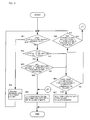
- Fig. 7 is a flowchart showing an algorithm, executed by a processor included in the CNC 6, for acquiring the power discontinuity information or the communication line disconnection information.
- the processor determines whether or not an alarm indicating that data is illegal or that the CNC 6 does not receive a reply is detected (step C1). If the alarm is not detected, the processor continues this detection until the alarm is detected. If the alarm is detected, the CNC 6 stops ordinary communication with the I/O units 1 to 5 (step C2) and transmits alarm information request signals 13a and 13b to all the I/O units 1 to 5 in order based on closeness to the CNC 6 (in order starting at the I/O unit 1) (step C3). The processor determines whether each of the I/O units 1 to 5 transmits a reply to the CNC 6 (step C4).
- step C4 determines in step C4 that each of the I/O units 1 to 5 transmits a reply to the CNC 6
- the processor stores the alarm information for which the I/O units 1 to 5 transmit replies to the CNC 6 in a storage device (not shown) included in the CNC 6 (step C7) and returns to the step C3, where the processor transmits the alarm information request signals 13a and 13b to all the I/O units 1 to 5.
- step C4 determines that none of the I/O units 1 to 5 transmit a reply to the CNC 6
- step C5 determines that none of the I/O units 1 to 5 transmit a reply to the CNC 6
- the processor proceeds from step C4 (determination result: No) to a step C5, where the processor executes an analysis of cause for an alarm. Further, the processor displays the cause for the alarm (step C6) and finishes this disconnection information acquisition processing.
Landscapes
- Engineering & Computer Science (AREA)
- General Physics & Mathematics (AREA)
- Computer Networks & Wireless Communication (AREA)
- Signal Processing (AREA)
- Automation & Control Theory (AREA)
- Physics & Mathematics (AREA)
- Human Computer Interaction (AREA)
- Manufacturing & Machinery (AREA)
- Environmental & Geological Engineering (AREA)
- Numerical Control (AREA)
- Communication Control (AREA)
- Small-Scale Networks (AREA)
- Selective Calling Equipment (AREA)
- Alarm Systems (AREA)
Applications Claiming Priority (1)
| Application Number | Priority Date | Filing Date | Title |
|---|---|---|---|
| JP2007216926A JP4291384B2 (ja) | 2007-08-23 | 2007-08-23 | 数値制御装置に接続されたioユニットの断線と電源断の検出方法 |
Publications (3)
| Publication Number | Publication Date |
|---|---|
| EP2028571A2 true EP2028571A2 (de) | 2009-02-25 |
| EP2028571A3 EP2028571A3 (de) | 2011-06-22 |
| EP2028571B1 EP2028571B1 (de) | 2013-12-11 |
Family
ID=39956129
Family Applications (1)
| Application Number | Title | Priority Date | Filing Date |
|---|---|---|---|
| EP08160124.7A Active EP2028571B1 (de) | 2007-08-23 | 2008-07-10 | Verfahren zur Erkennung von Verbindungsunterbrechungen und Stromlecks in einer mit einem numerischen Kontrollgerät verbundenen I/O-Einheit |
Country Status (4)
| Country | Link |
|---|---|
| US (1) | US7940057B2 (de) |
| EP (1) | EP2028571B1 (de) |
| JP (1) | JP4291384B2 (de) |
| CN (1) | CN101373381B (de) |
Cited By (1)
| Publication number | Priority date | Publication date | Assignee | Title |
|---|---|---|---|---|
| CN107329459A (zh) * | 2017-06-30 | 2017-11-07 | 张碧陶 | 一种集成运动控制和逻辑控制的数控系统 |
Families Citing this family (7)
| Publication number | Priority date | Publication date | Assignee | Title |
|---|---|---|---|---|
| CN102343632B (zh) * | 2011-09-29 | 2015-09-16 | 中国电子科技集团公司第四十五研究所 | 一种硅片多线切割断线检测的方法 |
| US20140082406A1 (en) * | 2012-09-18 | 2014-03-20 | Sandisk Technologies Inc. | Data protection through power loss prediction |
| JP5638045B2 (ja) * | 2012-09-20 | 2014-12-10 | ファナック株式会社 | 着脱可能なフィルタ回路を有する数値制御システム |
| JP5829247B2 (ja) * | 2013-10-16 | 2015-12-09 | ファナック株式会社 | デイジーチェーン接続されたioユニットへの一斉送信を行う数値制御装置 |
| JP5987069B2 (ja) | 2015-01-16 | 2016-09-06 | ファナック株式会社 | シリアル通信信号監視による内部レジスタ自己リセット機能を備えた数値制御システム |
| JP6546055B2 (ja) * | 2015-09-28 | 2019-07-17 | ファナック株式会社 | 数値制御システム |
| CN105372547A (zh) * | 2015-11-13 | 2016-03-02 | 谢贺年 | El冷光技术在数控维修中的应用 |
Citations (4)
| Publication number | Priority date | Publication date | Assignee | Title |
|---|---|---|---|---|
| JPS60224349A (ja) | 1984-04-23 | 1985-11-08 | Oki Electric Ind Co Ltd | 停電検出方式 |
| JPH05211560A (ja) | 1991-03-19 | 1993-08-20 | Fujitsu Ltd | データ障害検出方式 |
| WO2001038982A1 (en) | 1999-11-22 | 2001-05-31 | Seagate Technology Llc | Peer to peer interconnect diagnostics |
| JP2003209590A (ja) | 2002-01-15 | 2003-07-25 | Nec Access Technica Ltd | 電源断情報送信/検出方式 |
Family Cites Families (16)
| Publication number | Priority date | Publication date | Assignee | Title |
|---|---|---|---|---|
| US4292668A (en) * | 1979-01-31 | 1981-09-29 | Honeywell Information Systems Inc. | Data processing system having data multiplex control bus cycle |
| US4366350A (en) * | 1979-02-09 | 1982-12-28 | Stromberg-Carlson Corporation | Control system for telephone switching system |
| JPS573153A (en) | 1980-06-06 | 1982-01-08 | Fujitsu Ltd | Fault detection system |
| JPS6146654A (ja) | 1984-08-10 | 1986-03-06 | Nippon Telegr & Teleph Corp <Ntt> | 電源断遠隔検出装置 |
| JPH04349733A (ja) | 1991-05-28 | 1992-12-04 | Fujitsu Ltd | 通信端局装置増設時の試験方法 |
| SG43902A1 (en) * | 1991-12-09 | 1997-11-14 | Yokogawa Electric Corp | Distributed control system |
| JPH06177902A (ja) | 1992-12-04 | 1994-06-24 | Toshiba Corp | 通信ネットワークシステムの障害監視装置 |
| JPH08154101A (ja) | 1994-11-28 | 1996-06-11 | Matsushita Electric Works Ltd | ネットワーク管理方法 |
| US5723848A (en) * | 1996-01-16 | 1998-03-03 | Intech 21, Inc. | Heating cable control and monitoring method and system |
| JP3838772B2 (ja) * | 1998-02-04 | 2006-10-25 | Necエンジニアリング株式会社 | 電源障害情報通知機能を備えた通信装置 |
| AU5652700A (en) | 1999-09-24 | 2001-03-29 | Nintendo Co., Ltd. | Method and apparatus for providing non-photorealistic cartoon outlining within a 3D vodeographic system |
| US7480831B2 (en) * | 2003-01-23 | 2009-01-20 | Dell Products L.P. | Method and apparatus for recovering from a failed I/O controller in an information handling system |
| CA2457174A1 (en) * | 2003-07-30 | 2005-01-30 | Matsushita Electric Industrial Co., Ltd. | Data transmission apparatus and data transmission system |
| CN2852147Y (zh) * | 2005-12-05 | 2006-12-27 | 广东珠江开关有限公司 | 电力线路断线报警装置 |
| CN1996031A (zh) * | 2006-01-05 | 2007-07-11 | 苏州宇达电通有限公司 | 故障检测系统以及方法 |
| CN200997211Y (zh) * | 2006-11-20 | 2007-12-26 | 浙江天煌科技实业有限公司 | 数控机床四合一电气控制与维修实训装置 |
-
2007
- 2007-08-23 JP JP2007216926A patent/JP4291384B2/ja active Active
-
2008
- 2008-07-10 EP EP08160124.7A patent/EP2028571B1/de active Active
- 2008-07-17 US US12/174,849 patent/US7940057B2/en active Active
- 2008-07-24 CN CN2008101340664A patent/CN101373381B/zh active Active
Patent Citations (4)
| Publication number | Priority date | Publication date | Assignee | Title |
|---|---|---|---|---|
| JPS60224349A (ja) | 1984-04-23 | 1985-11-08 | Oki Electric Ind Co Ltd | 停電検出方式 |
| JPH05211560A (ja) | 1991-03-19 | 1993-08-20 | Fujitsu Ltd | データ障害検出方式 |
| WO2001038982A1 (en) | 1999-11-22 | 2001-05-31 | Seagate Technology Llc | Peer to peer interconnect diagnostics |
| JP2003209590A (ja) | 2002-01-15 | 2003-07-25 | Nec Access Technica Ltd | 電源断情報送信/検出方式 |
Cited By (1)
| Publication number | Priority date | Publication date | Assignee | Title |
|---|---|---|---|---|
| CN107329459A (zh) * | 2017-06-30 | 2017-11-07 | 张碧陶 | 一种集成运动控制和逻辑控制的数控系统 |
Also Published As
| Publication number | Publication date |
|---|---|
| EP2028571A3 (de) | 2011-06-22 |
| US7940057B2 (en) | 2011-05-10 |
| CN101373381A (zh) | 2009-02-25 |
| US20090051367A1 (en) | 2009-02-26 |
| JP2009053734A (ja) | 2009-03-12 |
| CN101373381B (zh) | 2011-06-15 |
| EP2028571B1 (de) | 2013-12-11 |
| JP4291384B2 (ja) | 2009-07-08 |
Similar Documents
| Publication | Publication Date | Title |
|---|---|---|
| EP2028571A2 (de) | Verfahren zur Erkennung von Verbindungsunterbrechungen und Stromlecks in einer mit einem numerischen Kontrollgerät verbundenen I/O-Einheit | |
| US6314476B1 (en) | Network adapter enabling bidirectional monitoring of a terminal device between a computer and a managing device | |
| JP5096905B2 (ja) | サーバ装置及びそのリンク回復処理方法 | |
| CN102541791A (zh) | 数据传送装置及其控制方法 | |
| US5537535A (en) | Multi-CPU system having fault monitoring facility | |
| RU2586580C2 (ru) | Обнаружение конфликтов в системах шин eia-485 | |
| EP1282265A2 (de) | Medienumsetzer mit Test Manager | |
| US7924750B1 (en) | Method and apparatus for establishing a communication mode between network devices in a network | |
| JP4681960B2 (ja) | 通信装置、通信装置の通信方法及びコンピュータプログラム | |
| EP1391827B1 (de) | Übertragungsvorrichtung und übertragungsverfahren | |
| US6643816B1 (en) | Transmitting apparatus and error handling method in transmitting apparatus | |
| GB2308904A (en) | SCSI bus extension over the ethernet | |
| EP2574012A1 (de) | Bussteuerungsvorrichtung und bussteuerungsverfahren | |
| JP4337605B2 (ja) | 信号伝送システムおよび画像形成装置 | |
| JP3445443B2 (ja) | 通信制御方法 | |
| JPH08202207A (ja) | オプション機器接続状態検知装置 | |
| JP4866288B2 (ja) | データ通信装置およびデータ回線終端装置 | |
| JP3910903B2 (ja) | 制御パケットの受信方法及び受信装置 | |
| JP3095060B2 (ja) | Atmスイッチ装置 | |
| KR100427764B1 (ko) | 서로 다른 데이터 버스를 가지는 디바이스들의 정합 장치 | |
| KR100485483B1 (ko) | 신호 전송 시스템 및 방법 | |
| JPH07264212A (ja) | 警報情報転送方式 | |
| KR100249729B1 (ko) | 백플레인상의 디바이스간 메시지 통신 장치 | |
| JP2006174012A (ja) | 負荷分散装置を含むネットワーク物理接続関係探索方法 | |
| JP2005051539A (ja) | シーケンス状態監視システム |
Legal Events
| Date | Code | Title | Description |
|---|---|---|---|
| PUAI | Public reference made under article 153(3) epc to a published international application that has entered the european phase |
Free format text: ORIGINAL CODE: 0009012 |
|
| AK | Designated contracting states |
Kind code of ref document: A2 Designated state(s): AT BE BG CH CY CZ DE DK EE ES FI FR GB GR HR HU IE IS IT LI LT LU LV MC MT NL NO PL PT RO SE SI SK TR |
|
| AX | Request for extension of the european patent |
Extension state: AL BA MK RS |
|
| RAP1 | Party data changed (applicant data changed or rights of an application transferred) |
Owner name: FANUC CORPORATION |
|
| PUAL | Search report despatched |
Free format text: ORIGINAL CODE: 0009013 |
|
| AK | Designated contracting states |
Kind code of ref document: A3 Designated state(s): AT BE BG CH CY CZ DE DK EE ES FI FR GB GR HR HU IE IS IT LI LT LU LV MC MT NL NO PL PT RO SE SI SK TR |
|
| AX | Request for extension of the european patent |
Extension state: AL BA MK RS |
|
| RIC1 | Information provided on ipc code assigned before grant |
Ipc: H04L 12/26 20060101ALI20110513BHEP Ipc: G05B 19/4067 20060101ALI20110513BHEP Ipc: G05B 19/042 20060101AFI20081119BHEP |
|
| 17P | Request for examination filed |
Effective date: 20111219 |
|
| AKX | Designation fees paid |
Designated state(s): DE |
|
| GRAP | Despatch of communication of intention to grant a patent |
Free format text: ORIGINAL CODE: EPIDOSNIGR1 |
|
| INTG | Intention to grant announced |
Effective date: 20130703 |
|
| RIN1 | Information on inventor provided before grant (corrected) |
Inventor name: HADA, KOUJI Inventor name: SONE, YUJI |
|
| GRAS | Grant fee paid |
Free format text: ORIGINAL CODE: EPIDOSNIGR3 |
|
| GRAA | (expected) grant |
Free format text: ORIGINAL CODE: 0009210 |
|
| AK | Designated contracting states |
Kind code of ref document: B1 Designated state(s): DE |
|
| REG | Reference to a national code |
Ref country code: DE Ref legal event code: R096 Ref document number: 602008029190 Country of ref document: DE Effective date: 20140206 |
|
| REG | Reference to a national code |
Ref country code: DE Ref legal event code: R097 Ref document number: 602008029190 Country of ref document: DE |
|
| PLBE | No opposition filed within time limit |
Free format text: ORIGINAL CODE: 0009261 |
|
| STAA | Information on the status of an ep patent application or granted ep patent |
Free format text: STATUS: NO OPPOSITION FILED WITHIN TIME LIMIT |
|
| 26N | No opposition filed |
Effective date: 20140912 |
|
| REG | Reference to a national code |
Ref country code: DE Ref legal event code: R097 Ref document number: 602008029190 Country of ref document: DE Effective date: 20140912 |
|
| REG | Reference to a national code |
Ref country code: DE Ref legal event code: R082 Ref document number: 602008029190 Country of ref document: DE Representative=s name: HL KEMPNER PATENTANWAELTE, SOLICITORS (ENGLAND, DE Ref country code: DE Ref legal event code: R082 Ref document number: 602008029190 Country of ref document: DE Representative=s name: HL KEMPNER PATENTANWALT, RECHTSANWALT, SOLICIT, DE Ref country code: DE Ref legal event code: R082 Ref document number: 602008029190 Country of ref document: DE Representative=s name: HL KEMPNER PARTG MBB, DE |
|
| PGFP | Annual fee paid to national office [announced via postgrant information from national office to epo] |
Ref country code: DE Payment date: 20250620 Year of fee payment: 18 |