EP2030834A1 - Abmontierbarer fahrzeugsitz - Google Patents
Abmontierbarer fahrzeugsitz Download PDFInfo
- Publication number
- EP2030834A1 EP2030834A1 EP07730372A EP07730372A EP2030834A1 EP 2030834 A1 EP2030834 A1 EP 2030834A1 EP 07730372 A EP07730372 A EP 07730372A EP 07730372 A EP07730372 A EP 07730372A EP 2030834 A1 EP2030834 A1 EP 2030834A1
- Authority
- EP
- European Patent Office
- Prior art keywords
- seat
- seat according
- free end
- articulated
- articulation shaft
- Prior art date
- Legal status (The legal status is an assumption and is not a legal conclusion. Google has not performed a legal analysis and makes no representation as to the accuracy of the status listed.)
- Granted
Links
- 230000007246 mechanism Effects 0.000 claims abstract description 91
- 230000008878 coupling Effects 0.000 claims abstract description 41
- 238000010168 coupling process Methods 0.000 claims abstract description 41
- 238000005859 coupling reaction Methods 0.000 claims abstract description 41
- 230000003187 abdominal effect Effects 0.000 claims abstract description 5
- 230000003100 immobilizing effect Effects 0.000 claims description 16
- 230000037431 insertion Effects 0.000 claims description 12
- 238000003780 insertion Methods 0.000 claims description 12
- 239000002184 metal Substances 0.000 claims description 12
- 239000004744 fabric Substances 0.000 claims description 10
- 210000004197 pelvis Anatomy 0.000 claims description 3
- 230000000717 retained effect Effects 0.000 claims description 3
- 238000000605 extraction Methods 0.000 description 2
- 230000014759 maintenance of location Effects 0.000 description 2
- 230000002093 peripheral effect Effects 0.000 description 2
- 238000011084 recovery Methods 0.000 description 2
- 206010039203 Road traffic accident Diseases 0.000 description 1
- 208000020339 Spinal injury Diseases 0.000 description 1
- 239000000463 material Substances 0.000 description 1
Images


Classifications
-
- B—PERFORMING OPERATIONS; TRANSPORTING
- B60—VEHICLES IN GENERAL
- B60R—VEHICLES, VEHICLE FITTINGS, OR VEHICLE PARTS, NOT OTHERWISE PROVIDED FOR
- B60R22/00—Safety belts or body harnesses in vehicles
-
- B—PERFORMING OPERATIONS; TRANSPORTING
- B60—VEHICLES IN GENERAL
- B60N—SEATS SPECIALLY ADAPTED FOR VEHICLES; VEHICLE PASSENGER ACCOMMODATION NOT OTHERWISE PROVIDED FOR
- B60N2/00—Seats specially adapted for vehicles; Arrangement or mounting of seats in vehicles
- B60N2/005—Arrangement or mounting of seats in vehicles, e.g. dismountable auxiliary seats
- B60N2/015—Attaching seats directly to vehicle chassis
- B60N2/01508—Attaching seats directly to vehicle chassis using quick release attachments
- B60N2/01516—Attaching seats directly to vehicle chassis using quick release attachments with locking mechanisms
- B60N2/01558—Attaching seats directly to vehicle chassis using quick release attachments with locking mechanisms with key and slot
- B60N2/01575—Attaching seats directly to vehicle chassis using quick release attachments with locking mechanisms with key and slot key sliding inside the vehicle floor or rail
-
- B—PERFORMING OPERATIONS; TRANSPORTING
- B60—VEHICLES IN GENERAL
- B60N—SEATS SPECIALLY ADAPTED FOR VEHICLES; VEHICLE PASSENGER ACCOMMODATION NOT OTHERWISE PROVIDED FOR
- B60N2/00—Seats specially adapted for vehicles; Arrangement or mounting of seats in vehicles
- B60N2/24—Seats specially adapted for vehicles; Arrangement or mounting of seats in vehicles for particular purposes or particular vehicles
-
- B—PERFORMING OPERATIONS; TRANSPORTING
- B60—VEHICLES IN GENERAL
- B60N—SEATS SPECIALLY ADAPTED FOR VEHICLES; VEHICLE PASSENGER ACCOMMODATION NOT OTHERWISE PROVIDED FOR
- B60N2/00—Seats specially adapted for vehicles; Arrangement or mounting of seats in vehicles
- B60N2/68—Seat frames
- B60N2/682—Joining means
- B60N2002/684—Joining means the back rest being mounted or joined with an easy attachment system to the seat
-
- B—PERFORMING OPERATIONS; TRANSPORTING
- B60—VEHICLES IN GENERAL
- B60R—VEHICLES, VEHICLE FITTINGS, OR VEHICLE PARTS, NOT OTHERWISE PROVIDED FOR
- B60R22/00—Safety belts or body harnesses in vehicles
- B60R22/001—Knee, leg or head belts
Definitions
- the invention comes within the technical field of seats for vehicles and particularly in the sector of vehicle seats that are at least partially separable from the structure of a vehicle in the event of rescue.
- the first drawback is that the equipment has to be available at the moment of the rescue, which is not always the case, as for example in situations in which the rescue has to be carried out with considerable urgency, even before the arrival of the recovery teams at the site of the accident, and when, in the case of a multiple accident, the recovery teams do not have sufficient equipment for being applied to all the injured people needing it.
- the present invention has the aim of achieving the desirable objectives mentioned above by means of a detachable vehicle seat, which consists of a back structure and a seat structure, means of articulation with at least one articulation shaft, in order to articulate the back structure to the seat structure, coupling means for coupling the seat structure to the back structure and securing means for securing the seat structure to a part of the vehicle floor, this seat also including a rapid detachment mechanism that permits the seat to be decoupled from the back.
- the coupling means include at least one first left vertical plate attached to a rear part of the left side of the back structure and at least one first right vertical plate attached to a lower part of the right side of the back structure, along with at least one second left vertical plate attached to a rear part of the left side of the seat structure and at least one second right vertical plate attached to a lower part of the right side of the seat structure, the vertical plates presenting separate passage holes.
- the passage hole in the first left vertical plate and the hole in the second left vertical plate are aligned, and the passage hole in the first right vertical plate and the hole in the second right vertical plate are aligned.
- the rapid detachment mechanism can consist of rapid detachment means which respectively fix the second left vertical plate and the second right vertical plate to the back structure and/or rapid detachment means which respectively fix the first left vertical plate and the first right vertical plate to the seat structure.
- the rapid detachment means can be pins, screws threaded into the structure and threaded studs projecting from the structure with nuts.
- the coupling means include two first left vertical plates and two first right vertical plates
- the second left vertical plate is arranged between the first left vertical plates and the second right vertical plate between the first right vertical plates.
- the rapid detachment mechanism can consist of rapid detachment means which respectively fix the second left vertical plate and the second right vertical plate to the back structure.
- the rapid detachment mechanism consists of rapid detachment means which respectively fix the first left vertical plate and the first right vertical plate to the seat structure.
- the rapid detachment mechanism can consist of a left catch mechanism applied to one end of the left articulation shaft, and a right catch mechanism applied to one end of the right articulation shaft, or a left pawl mechanism applied to one end of the left articulation shaft, and a right pawl mechanism applied to one end of the right articulation shaft.
- the rapid detachment mechanism can likewise consist of separate movable bolts which respectively constitute the left articulation shaft and the right articulation shaft, in which case each bolt has a head of diameter much wider than the diameter of the passage holes that it traverses, and a threaded end which is screwed into a securing element such as for example a nut or a block attached to the structure of the seat.
- the rapid detachment mechanism consists of a left clasping mechanism and a right clasping mechanism.
- Each clasping mechanism includes an integral part fixed to a structural part selected from between a part of the back structure and a part of the seat structure, which clasps an end part of an articulation shaft, and a movable part coupled to the integral part by movable coupling means.
- the integral part clasps at most a half of the perimeter of the articulation shaft.
- the clasping mechanism can include separate lateral projections on both sides respectively of the integral part and of the movable part, in such a way that the lateral projection of one side of the integral part is in contact with the lateral projection of the movable part.
- the lateral projections are joined by movable coupling means.
- the movable part can include a first side articulated to the integral part and a second side, opposite to the first side, in which the movable coupling means are provided.
- the movable coupling means can be rapid detachment screws which traverse one of the lateral projections and thread into the other lateral projection and screws which traverse the pairs of lateral projections which are in contact with each other and secured with rapid detachment nuts.
- the rapid detachment mechanism includes a left articulated body and a right articulated body arranged in such a way that each articulated body clasps an end part of an articulation shaft and includes an integral section fixed to a structural part selected from between a part of the back structure and a part of the seat structure, with the integral section clasping at most a half of the perimeter of the articulation shaft.
- the articulated body also includes a first tilting part which includes a free end part and an end part articulated to the integral section, opposite to the free end part, and a second tilting part which includes a free end part and an end part articulated to the integral section, opposite to the free end part.
- the tilting parts are joined together in the zone of overlap by rapid release means.
- at least the first tilting part can include in its free end a metal strip which is superimposed on the free end part of the second tilting part forming a zone of overlap in which the tilting parts are joined together by rapid release means.
- the rapid release means can include, in the free end parts of the second tilting parts, separate aligned openings in which an immobilizing element is inserted selected from between extractable bolts and rapid detachment screws which traverse one of the tilting parts and which thread into the free end part of the other tilting part.
- the rapid release means can include, in the free end parts of the second tilting parts, separate tabs which project outwards from said free end parts and which are provided with aligned passage holes in which an immobilizing element is inserted selected from between extractable bolts and rapid detachment screws which traverse one of the tilting parts and which thread into the free end part of the other tilting part.
- the rapid detachment mechanism includes a left articulated bushing and a right articulated bushing.
- Each articulated bushing clasps an end part of an articulation shaft and includes an integral section fixed to a structural part selected from between a part of the back structure and a part of the seat structure.
- the integral section clasps at most a half of the perimeter of the articulation shaft.
- the articulated bushing can also include a first tilting part which includes a free end part and an end part articulated to the integral section, opposite to the free end part, and a second tilting section which includes a free end part and an end part articulated to the integral section, opposite to the free end part.
- At least the first tilting section includes in its free end a metal strip which is superimposed on the free end part of the second tilting section forming a zone of overlap in which the free end parts of the second sections present separate aligned openings in which an immobilizing element is inserted selected from between extractable bolts and rapid detachment screws which traverse one of the tilting parts and which thread into at least the opening in the free end part of the second tilting section.
- the metal strip in the first movable section can also be articulated in the first section.
- the articulated bushing can furthermore include an additional metal strip, articulated in the free end part of the second movable section, and which overlaps with said strip of the first section.
- the rapid detachment mechanism can include a pyrotechnic device which actuates a guillotine mechanism that acts on a weakened part of the coupling means, or which is inserted in a weakened part of the coupling means.
- the seat is secured to at least two lower running guides fixed to the floor of the vehicle by means of a rapid release mechanism for the securing of the seat in those lower guides.
- the rapid release mechanism can include an upper runner in the form of an inverted U which clasps the sides of the lower runner, and at least two securing bolts, which emerge vertically and beneath the structure of one side of the seat, which have separate widened heads at their free ends and which penetrate through the upper surface of the upper runner via respective holes.
- a fastening strip is provided inside horizontal axial rails in the interior of the upper runner.
- the fastening strip In its upper face the fastening strip presents at least two axial grooves, each of which finishes in at least its ends in an insertion hole for one of the securing bolts which has a perimeter greater than the perimeter of the head of the securing bolt. Between the upper surface of the lower runner and the inner surface of the fastening strip there exists an axial space which has a height greater than the height of the heads of the securing bolts.
- the fastening strip is able to slide between a release position in which the insertion holes are aligned with the holes in the upper runner and a locking position in which the insertion holes are out of alignment with the holes in the upper runner, and the stems of the securing bolts are to be found in the respective axial grooves and the heads of the securing bolts remain retained beneath the fastening strip.
- movable immobilizing means which immobilize the fastening strip in a locking position.
- These immobilizing means can, for example, be a locking pin inserted in separate passage holes aligned in the upper runner and in the fastening strip.
- the seat also includes a system of tying in order to immobilize at least the back of an injured person to the back of the seat.
- This system of tying includes at least one first strap coupled to the structure of the back part of the seat in a zone corresponding to the abdominal zone of the person and a headrest in which is coupled at least one second strap in a zone corresponding to the head zone of the person.
- the system of tying can include at least one third strap coupled to the structure of the back part of the seat in a zone corresponding to the chest zone of the person and/or a system of fourth straps coupled to the structure of the back part of the seat at the height of the shoulders of the person.
- This embodiment preferably also includes some compartments with access mouths integrated into the back of the seat and dimensioned for housing the straps when they are not being used.
- the seat preferably also includes covers for covering the compartments when the straps are housed in them, and because the covers include means of closure.
- the covers can be flaps made of the fabric of the seat, in which case the means of closure can be zips provided in the edges of the flaps and in the edges of the fabric surrounding the access mouth of the compartment, or separate Velcro elements arranged in parts of the overlaps and in parts of the fabric in contact with each other.
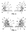
- Figure 1 shows the usual position of a seat which includes a back structure 1 and a seat structure 2 coupled by means of articulation 3 in a part of the floor 5 of a vehicle. Coupled in the upper part of the back structure, in a way that is in itself conventional, is a headrest 32. As shown in figure 2 , it can be seen that the back structure 1 is articulated to the seat structure 2 in an articulation shaft 11, which traverses a first vertical plate 7a attached to the back structure 1 and a second vertical plate 8a attached to the seat structure 2.
- the coupling means include two left vertical plates 7a,7c and two right vertical plate 7b,7d, a second left vertical plate 8a arranged between the first left vertical plates 7a,7c and a second right vertical plate 8b arranged between the first right vertical plates 7b,7d.
- the vertical plates present aligned passage holes 9.
- a left articulation shaft 11 traverses the passage holes 9 in the left vertical plates 7a,7c,8a,8c and a right articulation shaft 12 traverses the passage holes 9 in the right vertical plates 7b,7d,8b,8d, the back structure 1 thus being articulated to the seat structure 2.
- the shafts 11,12 are separate studs 10b projecting from a structural element 17 of the back structure, with threaded ends into which screw the rapid release nuts 10b.
- another rapid detachment mechanism which consists of rapid detachment means 10 in the form of respective screws which thread into the back structure in such a way that they respectively fix the first left vertical plate 7a and the first right vertical plate 7b to the back structure 1.
- each bolt 11,12 includes a head 11 b,12b of diameter wider than the diameter of the passage holes 9 which it traverses, and a threaded end 11c,12d which screws into a fixing element (17).
- another rapid detachment mechanism which consists of rapid detachment means 10 in the form of respective screws which thread into the seat structure 2 in such a way that they respectively fix the second left vertical plate 8a and the second right vertical plate 8b to the seat structure 2.
- the coupling means of the back structure 1 to the seat structure 2 consist of a left articulation shaft 11 in the form of a stud which traverses the passage holes 9 in the left vertical plates 7a,8a,8c and a right articulation shaft 12, also in the form of a stud, which traverses the passage holes 9 in the right vertical plates 7b,8b,8d.
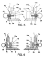
- the rapid detachment mechanism consists of a left catch mechanism 13 applied to the free end 11a of the left stud 11, and a right catch mechanism 14 applied to the free end 12a of the right stud 12.
- the catch mechanisms 13,14 are actuated by means of respective cables 13a,14a which project from the back of the seat and are connected to some stay elements (not shown in figure 5 ).
- the catches 13b,14b rise up to the position shown with the line of dashes and exit from a peripheral retention recess for the respective studs 11,12 in such a way that the studs 11,12 can be extracted from the passage holes 9 by pulling the respective rings 38, with the back structure 1 becoming decoupled from the seat structure 2.
- the coupling means of the back structure 1 to the seat structure 2 also consist of a left articulation shaft 11 in the form of a stud which traverses the passage holes 9 in the left vertical plates 7a,8a,8c and a right articulation shaft 12, also in the form of a stud, which traverses the passage holes 9 in the right vertical plates 7b,8b,8d.
- the rapid detachment mechanism consists of a left pawl mechanism 15 applied to the free end 11 a of the left stud 11, and a right pawl mechanism 16 applied to the free end 12a of the right stud 12.
- the pawl mechanisms 15,16 are actuated by means of respective cables 15a,16a which project from the back of the seat and are connected to some stay elements (not shown in figure 6 ).
- the cables 15a,16a are pulled, the pawls 15b,16b rise up to the position shown with the line of dashes and exit from a peripheral retention groove for the respective studs 11,12 in such a way that the studs 11,12 can be extracted from the passage holes 9 by pulling the respective rings 38, with the back structure 1 becoming decoupled from the seat structure 2.
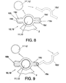
- Figure 7 shows a later embodiment in which the back part 1 is articulated to the seat part 2 by means of an articulation shaft 11,12, which is clasped by left 18,19,21 and right 18',19',21' rapid detachment mechanisms which will be described in further detail on the basis of figures 8 to 14 .
- the rapid detachment mechanism consists of a left clasping mechanism 18 and a right clasping mechanism 18'.
- Each clasping mechanism 18,18' clasps the articulation shaft 11,12 and includes an integral part 18a fixed to the seat structure 2, along with a movable part 18b coupled to the integral part 18a by movable coupling means 18c.
- the integral part 18a clasps less than half of the perimeter of the articulation shaft 11,12.
- Both sides of the integral part 18a and of the movable part 18b are extended in separate lateral projections 18d in such a way that on each side the lateral projection 18d of one side of the integral part 18a makes contact with the lateral projection 18d of the movable part 18b and the lateral projections 18d are joined by movable coupling means 18c which can be, for example, rapid detachment screws which traverse one of the lateral projections 18d and thread into the lateral projection 18d with which it is in contact, or screws which traverse the pairs of lateral projections 18d which are in contact with each other and secured with rapid detachment nuts.
- movable coupling means 18c can be, for example, rapid detachment screws which traverse one of the lateral projections 18d and thread into the lateral projection 18d with which it is in contact, or screws which traverse the pairs of lateral projections 18d which are in contact with each other and secured with rapid detachment nuts.
- the movable part 18b can be moved to a distant position 18b' in such a way that the shaft 11,12 can be extracted towards the position 11',12' together with the back structure.
- the movable part 18b includes a first side articulated to the integral part 18a and a second side, opposite to the first side, in which the movable coupling means 18c are provided which, as in the embodiment of figure 8 , can be a rapid detachment screw which traverses one of the lateral projections 18d and threads into the lateral projection 18d or a screw which traverses the pairs of lateral projections 18d and is secured with rapid detachment nuts.
- the coupling means 18c when the coupling means 18c are released the movable part 18b can tilt to the open position 18b' in such a way that the shaft 11,12 can be extracted towards the position 11',12' together with the back structure.
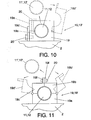
- the rapid detachment mechanism includes a left articulated body 19 and a right articulated body 19'.
- Each articulated body 19,19' clasps the articulation shaft 11,12 and includes an integral part 19a fixed to the seat structure 2, along with a movable part 19b coupled to the integral part 19a by movable coupling means 20 for rapid release.
- the integral part 19a clasps less than half of the perimeter of the articulation shaft 11,12.
- a metal strip 19d which makes contact with the side of the integral part 19a.
- the movable coupling means 20 for rapid release can, for example, be a rapid detachment screw which traverses the strip 19d and threads into the integral part 19a or, as shown with the line of dashes in figure 10 , a rapid detachment screw which traverses the movable part 19d and threads into the integral part 19a.
- the parts 19a,19b are articulated in a tilting shaft in such a way that, when the coupling means 20 are released, the movable part 19b can tilt to an open position 19b' so that the shaft 11,12 can be extracted towards the position 11',12' together with the back structure.
- the rapid detachment mechanism includes an articulated body 19,19' which also includes a first tilting part 19b which includes a free end part and an end part articulated to the integral section 19a, opposite to the free end part, and a second tilting part 19c which includes a free end part and an end part articulated to the integral section 19a, opposite to the free end part.
- the tilting parts 19a,19b are joined together in the zone of overlap by rapid release means which include, in the free end parts of the tilting parts 19b,19c, separate tabs 19f which project outwards from said free end parts and which are provided with aligned passage holes 19g in which an immobilizing element 20 is inserted selected from between extractable bolts and rapid detachment screws provided in said passage holes 19g.
- the rapid detachment mechanism includes a left articulated bushing 21 and a right articulated bushing 21'.
- Each articulated bushing 21,21' clasps an end part 11a, 12a of an articulation shaft 11,12 and includes an integral section 21 a fixed to a part of the seat structure 2.
- the integral section 21a also clasps at most a half of the perimeter of the articulation shaft 11,12.
- the articulated bushing 21, 21' can also include a first tilting section 21 b which includes a free end part and an end part articulated to the integral section 21a, opposite to the free end part, and a second tilting section 21 c which includes a free end part and an end part articulated to the integral section 21a, opposite to the free end part.
- the first tilting section 21 b includes in its free end a metal strip 21d articulated in the first movable section 21b which is superimposed with an additional strip (21e) articulated in the free end part of the second movable section 21c, in such a way that the additional strip 21 e overlaps with said strip 21 e of the first section 21b, forming a zone of overlap.
- the strips 21d,21e present separate aligned openings 21f in which an immobilizing element 20 is inserted which in the case of figures 12 to 14 is an extractable bolt.
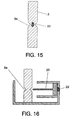
- FIG 15 can be seen an embodiment of the rapid detachment mechanism in which this consists of a pyrotechnic device 22 inserted in a weakened part 3a of the coupling means 3.
- a pyrotechnic device 22 explodes it breaks the weakened part 3a in such a way that the seat part becomes decoupled from the back part.
- FIG 16 can be seen another embodiment of the rapid detachment mechanism in which this consists of a pyrotechnic device 22 which actuates a guillotine mechanism 23 which acts on a weakened part 3a of the coupling means 3.
- a pyrotechnic device 22 explodes it launches the guillotine device 23 against the weakened part 3a which therefore becomes sectioned such that the seat part becomes decoupled from the back part.
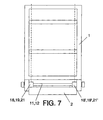
- FIGS 17 to 22 show an embodiment of the means of securing in which the seat structure (2) is secured to at least two lower running guides (24,24') fixed to the floor (5) of the vehicle (6) by means of separate rapid release mechanisms for the securing of the seat structure (2) in those lower guides (24,24').
- each rapid release mechanism includes an upper runner (25) in the form of an inverted U which clasps the sides of the lower runner (24), and at least two securing bolts (26), which emerge vertically and beneath the structure of one side of the seat structure (2), which have separate widened heads (26a) at their free ends and which penetrate through the upper surface of the upper runner (25) via respective holes 25a.
- the rapid release mechanism also includes a fastening strip (27) provided inside in horizontal axial rails (25b) in the interior of the upper runner (25) and which presents in its upper face at least two axial grooves (27a), each of which finishes in at least its ends in an insertion hole (27b) for a securing bolt (26), said insertion hole (27b) having a perimeter greater than the perimeter of the head (26a) of the securing bolt (26).
- movable immobilizing means are also provided which immobilize the fastening strip (27) in a locking position. Between the upper surface of the lower runner (24) and the inner surface of the fastening strip (27) there exists an axial space (28) which has a height greater than the height of the heads (26a) of the securing bolts (26).
- the fastening strip (27) is able to slide in those axial rails (25b) between a release position in which the insertion holes (27b) are aligned with the holes (25a) in the upper runner (25) and a locking position in which the insertion holes (27b) are out of alignment with the holes (25a) in the upper runner (25), and the stems (26b) of the securing bolts (26) are to be found to the respective axial grooves (27a) and the heads (26a) of the securing bolts (26) remain retained beneath the fastening strip (27).
- the movable immobilizing means are in this case a locking pin (29) inserted in separate passage holes aligned in the upper runner (25) and in the fastening strip (27).
- FIG. 23 to 25 an embodiment can be seen of a system of tying which serves to immobilize at least the back of an injured person (30), and which consists of two first straps (31) coupled to the structure of the back part (1) of the seat in a zone corresponding to the abdominal zone (30a) of the person (30) and a headrest (32) in which is coupled a set of second straps (33) in a zone corresponding to the head zone (30b) of the person (30).
- the system of tying also includes a third strap (34) coupled to the structure of the back part (1) of the seat in a zone corresponding to the chest zone (30c) of the person (30) along with a system of fourth straps (35) coupled to the structure of the back part (1) of the seat at the height of the shoulders (30d) of the person (30) and a system of fifth straps (36) coupled to the structure of the back part (1) of the seat at the height of the pelvis (30e) of the person (30).
- the seat is provided with compartments (37) with access mouths (37a) integrated into the back of the seat and dimensioned for housing the straps (31,33,34,35,36).
- covers (36b) for covering the access mouths (37a) of the compartments (37) when the straps (31,33,34,35,36) are housed in them.
- the covers (37b) are flaps made of the fabric of the seat and the means of closure are zips provided in the edges of the flaps and in the edges of the fabric surrounding the access mouth of the compartment.
- the means of closure can also be Velcro elements arranged in parts of the overlaps and in parts of the fabric in contact with each other.
Landscapes
- Engineering & Computer Science (AREA)
- Mechanical Engineering (AREA)
- Aviation & Aerospace Engineering (AREA)
- Transportation (AREA)
- Seats For Vehicles (AREA)
- Vehicle Waterproofing, Decoration, And Sanitation Devices (AREA)
- Forklifts And Lifting Vehicles (AREA)
Priority Applications (1)
| Application Number | Priority Date | Filing Date | Title |
|---|---|---|---|
| EP07730372.5A EP2030834B2 (de) | 2006-06-16 | 2007-03-09 | Abmontierbarer fahrzeugsitz |
Applications Claiming Priority (3)
| Application Number | Priority Date | Filing Date | Title |
|---|---|---|---|
| EP06380174 | 2006-06-16 | ||
| EP07730372.5A EP2030834B2 (de) | 2006-06-16 | 2007-03-09 | Abmontierbarer fahrzeugsitz |
| PCT/ES2007/000131 WO2007147908A1 (es) | 2006-06-16 | 2007-03-09 | Asiento desmontable para un vehículo |
Publications (3)
| Publication Number | Publication Date |
|---|---|
| EP2030834A1 true EP2030834A1 (de) | 2009-03-04 |
| EP2030834B1 EP2030834B1 (de) | 2010-05-12 |
| EP2030834B2 EP2030834B2 (de) | 2013-08-07 |
Family
ID=38833096
Family Applications (1)
| Application Number | Title | Priority Date | Filing Date |
|---|---|---|---|
| EP07730372.5A Not-in-force EP2030834B2 (de) | 2006-06-16 | 2007-03-09 | Abmontierbarer fahrzeugsitz |
Country Status (8)
| Country | Link |
|---|---|
| US (1) | US8136863B2 (de) |
| EP (1) | EP2030834B2 (de) |
| JP (1) | JP5438509B2 (de) |
| AT (1) | ATE467527T1 (de) |
| DE (1) | DE602007006485D1 (de) |
| ES (1) | ES2345791T5 (de) |
| PT (1) | PT2030834E (de) |
| WO (1) | WO2007147908A1 (de) |
Families Citing this family (9)
| Publication number | Priority date | Publication date | Assignee | Title |
|---|---|---|---|---|
| US4519253A (en) | 1983-04-29 | 1985-05-28 | Rosemount Inc. | Reactance measurement circuit with enhanced linearity |
| TR201811275T4 (tr) | 2016-03-07 | 2018-09-21 | Innovation And Safety S L | Sökülebilir koltuk. |
| WO2017165776A1 (en) * | 2016-03-25 | 2017-09-28 | Survivability Solutions Llc | Immobilization system for a vehicle seat |
| GB2555789A (en) * | 2016-11-08 | 2018-05-16 | Bae Systems Plc | Seat release system |
| CN108237952B (zh) * | 2016-12-26 | 2023-08-22 | 江苏卡威汽车工业集团有限公司 | 一种油电混合汽车 |
| SE541407C2 (en) * | 2017-02-15 | 2019-09-24 | Quick Seat Release Sweden Ab | A vehicle seat attachment arrangement |
| DE102017122387B4 (de) * | 2017-09-27 | 2025-12-04 | Airbus Operations Gmbh | Passagiersitzsystem für ein Transportmittel und Transportmittel damit |
| US12109919B2 (en) | 2022-05-17 | 2024-10-08 | Ford Global Technologies, Llc | Rotation assembly for a seating assembly |
| CN116279029B (zh) * | 2023-03-24 | 2025-10-10 | 广汽本田汽车有限公司 | 一种汽车座椅和汽车 |
Family Cites Families (41)
| Publication number | Priority date | Publication date | Assignee | Title |
|---|---|---|---|---|
| US2575221A (en) * | 1946-01-19 | 1951-11-13 | Internat Furniture Company | Seat structure with removable back |
| US4261349A (en) * | 1979-07-13 | 1981-04-14 | Nasa | Spine immobilization apparatus |
| DE3624295A1 (de) * | 1986-07-18 | 1988-01-21 | Keiper Recaro Gmbh Co | Rueckenlehnenrahmen fuer sitze, insbesondere fuer kraftfahrzeugsitze |
| CA2034924C (en) * | 1991-01-25 | 1995-12-05 | Dennis Brothers | Snap lock fitting for automotive seat backs |
| US5154476A (en) * | 1991-02-21 | 1992-10-13 | Hoover Universal, Inc. | Locking seat recliner |
| US5183314A (en) * | 1991-11-18 | 1993-02-02 | Milsco Manufacturing Company | Concealed mechanism for detachably mounting a vehicle seat |
| US5161275A (en) * | 1992-03-20 | 1992-11-10 | Safety Quest, Inc. | Vehicle seat liner to facilitate extraction of an injured driver |
| JP2532323B2 (ja) * | 1992-03-23 | 1996-09-11 | 日本電子工業株式会社 | 乗物用乗員拘束装置 |
| JPH0642468U (ja) * | 1992-11-19 | 1994-06-07 | ダイハツ工業株式会社 | 車両用シートのシートベルト格納構造 |
| FR2704492B1 (fr) * | 1993-04-27 | 1995-06-16 | Renault | Support de siege de vehicule automobile. |
| JP3518629B2 (ja) * | 1994-12-16 | 2004-04-12 | シロキ工業株式会社 | 腰 掛 |
| GB9500292D0 (en) † | 1995-01-07 | 1995-03-01 | Melfin Uk Ltd | Seat anchorage locking mechanism |
| FR2729439B1 (fr) * | 1995-01-16 | 1997-04-04 | Faure Bertrand Equipements Sa | Systeme de montage d'un element de siege sur un vehicule automobile |
| JPH1076872A (ja) * | 1996-09-04 | 1998-03-24 | Araco Corp | 車両用脱着シートの取付装置 |
| US5803549A (en) * | 1997-06-06 | 1998-09-08 | General Motors Corporation | Self-locking forkbolt |
| DE29712180U1 (de) * | 1997-07-10 | 1997-09-11 | Oettl, Heinrich, 81373 München | Vorrichtung zur schnellösbaren, verschiebbaren und schnell arretierbaren Befestigung eines Fahrzeugausrüstungsteiles, wie z.B. eines Sitzes |
| US5947515A (en) * | 1997-08-25 | 1999-09-07 | Fitch; John C. | Driver safety capsule |
| US5947562A (en) * | 1997-09-19 | 1999-09-07 | Sunrise Medical Hhg Inc. | Quick release seat |
| JP2001508693A (ja) * | 1997-09-28 | 2001-07-03 | ヴォルフガング シュテルツェンミューラー | 個々の肢或いは身体各部分を固定するための救急用支持器具 |
| US6254054B1 (en) * | 1997-10-03 | 2001-07-03 | Norco Industries, Inc. | Quick release mechanism for vehicle seating |
| DE19825439C2 (de) | 1998-05-29 | 2002-04-18 | Brose Fahrzeugteile | Entnehmbarer Fahrzeugsitz |
| US6250713B1 (en) * | 1998-07-24 | 2001-06-26 | Lear Corporation | Extractable seat |
| JP3163599B2 (ja) * | 1998-11-16 | 2001-05-08 | 桂司 古川 | 自動車シートベルト構造 |
| DE19930945C1 (de) † | 1999-07-05 | 2001-03-22 | Keiper Gmbh & Co | Befestigungsvorrichtung für den am Sitzteil oder Sitzrahmen festgelegten Beschlagteil eines Beschlages |
| DE19942976B4 (de) * | 1999-09-09 | 2005-11-10 | Keiper Gmbh & Co.Kg | Fahrzeugsitz mit Schnellmontageverbindung |
| JP3760979B2 (ja) | 1999-09-17 | 2006-03-29 | マツダ株式会社 | 車両用シート装置 |
| ES2226992T3 (es) * | 2000-03-09 | 2005-04-01 | Airbus Deutschland Gmbh | Asiento de pasajero con medios de seguridad. |
| AU2001281902A1 (en) * | 2000-06-28 | 2002-01-08 | Wolfgang Stelzenmuller | Rescue system and vehicle seat comprising one such rescue system |
| US6550858B1 (en) * | 2000-09-21 | 2003-04-22 | Lear Corporation | Extricable seat assembly |
| DE10102109A1 (de) * | 2000-12-29 | 2002-07-11 | Ingbuero Schimmelpfennig & Bec | Fahrzeugsitz |
| DE10112134B4 (de) † | 2001-03-14 | 2010-05-06 | Bayerische Motoren Werke Aktiengesellschaft | Fahrzeugsitz mit einer Rückenlehne |
| US20020149253A1 (en) * | 2001-04-14 | 2002-10-17 | Macdonald Glen | Novel seating apparatus |
| US7387125B2 (en) * | 2001-12-17 | 2008-06-17 | Marcelo Fernando Lamon | Controlled extrication module for motor vehicle crash injured people |
| ES2190760B1 (es) * | 2002-01-09 | 2005-10-01 | Jorge Porritt Lueiro | Dispositivo para evacuar un herido desde el asiento de un vehiculo accidentado. |
| KR100453026B1 (ko) | 2002-07-27 | 2004-10-14 | 대원산업 주식회사 | 자동 텀블 및 대좌 조립이 가능한 착탈식 시트 |
| US7111888B1 (en) * | 2003-09-09 | 2006-09-26 | Motorsports Builders, Llc | Molded safety seat |
| US6991285B1 (en) * | 2004-03-17 | 2006-01-31 | Hemenway Michael S | Reversible seatback for a vehicle |
| DE102004014879A1 (de) † | 2004-03-22 | 2005-10-13 | Sitech Sitztechnik Gmbh | Fahrzeugsitz |
| GB2413782B (en) * | 2004-05-08 | 2008-06-25 | Ennio Tabone | Tabar extrication device |
| DE102004029866A1 (de) | 2004-06-21 | 2006-01-12 | Daimlerchrysler Ag | Fondsitzeinrichtung |
| WO2008041072A2 (en) * | 2006-10-05 | 2008-04-10 | Craig Anthony Stephens | Means for accessing a vehicle in an emergency |
-
2007
- 2007-03-09 EP EP07730372.5A patent/EP2030834B2/de not_active Not-in-force
- 2007-03-09 PT PT07730372T patent/PT2030834E/pt unknown
- 2007-03-09 WO PCT/ES2007/000131 patent/WO2007147908A1/es not_active Ceased
- 2007-03-09 US US12/305,147 patent/US8136863B2/en not_active Expired - Fee Related
- 2007-03-09 ES ES07730372T patent/ES2345791T5/es active Active
- 2007-03-09 DE DE602007006485T patent/DE602007006485D1/de active Active
- 2007-03-09 AT AT07730372T patent/ATE467527T1/de not_active IP Right Cessation
- 2007-03-09 JP JP2009514820A patent/JP5438509B2/ja not_active Expired - Fee Related
Non-Patent Citations (1)
| Title |
|---|
| See references of WO2007147908A1 * |
Also Published As
| Publication number | Publication date |
|---|---|
| EP2030834B1 (de) | 2010-05-12 |
| DE602007006485D1 (de) | 2010-06-24 |
| JP5438509B2 (ja) | 2014-03-12 |
| ES2345791T3 (es) | 2010-10-01 |
| PT2030834E (pt) | 2010-08-11 |
| US20100001545A1 (en) | 2010-01-07 |
| ATE467527T1 (de) | 2010-05-15 |
| JP2009539691A (ja) | 2009-11-19 |
| EP2030834B2 (de) | 2013-08-07 |
| US8136863B2 (en) | 2012-03-20 |
| ES2345791T5 (es) | 2013-12-16 |
| WO2007147908A1 (es) | 2007-12-27 |
Similar Documents
| Publication | Publication Date | Title |
|---|---|---|
| EP2030834B1 (de) | Abmontierbarer fahrzeugsitz | |
| US5562326A (en) | Personal body restraint device | |
| EP3216645B1 (de) | Demontierbarer sitz | |
| EP1547921B1 (de) | Passagiersitz für eine Passagierkabine eines Verkehrsflugzeuges mit einer Sicherheits- und Informationseinrichtung | |
| WO2017126763A1 (ko) | 휴대용 차량용 안전벨트 체결장치 | |
| DE102005014997B4 (de) | Rückhaltesystem und Zudecke mit einer integrierten Rückhaltefunktion | |
| US4139215A (en) | Automobile safety belt | |
| US7448690B2 (en) | Child safety seat with emergency harness release | |
| US6874506B2 (en) | Rapid deployment seat-based releasable soft restraint system and method | |
| EP3755173B1 (de) | Schutzhelm und verfahren zur nutzung eines solchen | |
| DE102018104449A1 (de) | Mobile Sitzvorrichtung für ein Fortbewegungsmittel und Fortbewegungsmittel | |
| US8132864B2 (en) | Child safety seat with emergency harness release | |
| EP2463160A1 (de) | Sicherheitssystem für Krankenwagen-Personal | |
| DE102019108336B4 (de) | Rettungssystem | |
| DE202018104392U1 (de) | Kraftfahrzeugsitzauflage | |
| EP0953474A2 (de) | Sitzanordnung für der Personenbeförderung dienende Fahrzeuge | |
| DE60037591T2 (de) | Steifschalige schiene | |
| DE10031413A1 (de) | Rettungssystem und Fahrzeugsitz mit einem solchen Rettungssystem | |
| DE10207429A1 (de) | Sitz mit einem Rettungsgurtsystem sowie Rettungseinrichtung | |
| US20200307505A1 (en) | Immobilization System for a Vehicle Seat | |
| DE9403533U1 (de) | Beckengurtadapteranordnung | |
| CN120660974A (zh) | 一种锁止机构和折叠卧铺 | |
| GB2580070A (en) | Improvements relating to motor vehicles | |
| DE202019105622U1 (de) | Vorrichtung für die Rettung von Personen | |
| DE102004014879A1 (de) | Fahrzeugsitz |
Legal Events
| Date | Code | Title | Description |
|---|---|---|---|
| PUAI | Public reference made under article 153(3) epc to a published international application that has entered the european phase |
Free format text: ORIGINAL CODE: 0009012 |
|
| 17P | Request for examination filed |
Effective date: 20081211 |
|
| AK | Designated contracting states |
Kind code of ref document: A1 Designated state(s): AT BE BG CH CY CZ DE DK EE ES FI FR GB GR HU IE IS IT LI LT LU LV MC MT NL PL PT RO SE SI SK TR |
|
| AX | Request for extension of the european patent |
Extension state: AL BA HR MK RS |
|
| GRAP | Despatch of communication of intention to grant a patent |
Free format text: ORIGINAL CODE: EPIDOSNIGR1 |
|
| DAX | Request for extension of the european patent (deleted) | ||
| GRAS | Grant fee paid |
Free format text: ORIGINAL CODE: EPIDOSNIGR3 |
|
| GRAA | (expected) grant |
Free format text: ORIGINAL CODE: 0009210 |
|
| AK | Designated contracting states |
Kind code of ref document: B1 Designated state(s): AT BE BG CH CY CZ DE DK EE ES FI FR GB GR HU IE IS IT LI LT LU LV MC MT NL PL PT RO SE SI SK TR |
|
| REG | Reference to a national code |
Ref country code: GB Ref legal event code: FG4D |
|
| REG | Reference to a national code |
Ref country code: CH Ref legal event code: EP |
|
| REG | Reference to a national code |
Ref country code: IE Ref legal event code: FG4D |
|
| REF | Corresponds to: |
Ref document number: 602007006485 Country of ref document: DE Date of ref document: 20100624 Kind code of ref document: P |
|
| REG | Reference to a national code |
Ref country code: PT Ref legal event code: SC4A Free format text: AVAILABILITY OF NATIONAL TRANSLATION Effective date: 20100804 |
|
| REG | Reference to a national code |
Ref country code: NL Ref legal event code: VDEP Effective date: 20100512 |
|
| REG | Reference to a national code |
Ref country code: ES Ref legal event code: FG2A Ref document number: 2345791 Country of ref document: ES Kind code of ref document: T3 |
|
| LTIE | Lt: invalidation of european patent or patent extension |
Effective date: 20100512 |
|
| PG25 | Lapsed in a contracting state [announced via postgrant information from national office to epo] |
Ref country code: NL Free format text: LAPSE BECAUSE OF FAILURE TO SUBMIT A TRANSLATION OF THE DESCRIPTION OR TO PAY THE FEE WITHIN THE PRESCRIBED TIME-LIMIT Effective date: 20100512 Ref country code: LT Free format text: LAPSE BECAUSE OF FAILURE TO SUBMIT A TRANSLATION OF THE DESCRIPTION OR TO PAY THE FEE WITHIN THE PRESCRIBED TIME-LIMIT Effective date: 20100512 Ref country code: SE Free format text: LAPSE BECAUSE OF FAILURE TO SUBMIT A TRANSLATION OF THE DESCRIPTION OR TO PAY THE FEE WITHIN THE PRESCRIBED TIME-LIMIT Effective date: 20100512 |
|
| PG25 | Lapsed in a contracting state [announced via postgrant information from national office to epo] |
Ref country code: FI Free format text: LAPSE BECAUSE OF FAILURE TO SUBMIT A TRANSLATION OF THE DESCRIPTION OR TO PAY THE FEE WITHIN THE PRESCRIBED TIME-LIMIT Effective date: 20100512 Ref country code: IS Free format text: LAPSE BECAUSE OF FAILURE TO SUBMIT A TRANSLATION OF THE DESCRIPTION OR TO PAY THE FEE WITHIN THE PRESCRIBED TIME-LIMIT Effective date: 20100912 Ref country code: LV Free format text: LAPSE BECAUSE OF FAILURE TO SUBMIT A TRANSLATION OF THE DESCRIPTION OR TO PAY THE FEE WITHIN THE PRESCRIBED TIME-LIMIT Effective date: 20100512 Ref country code: SI Free format text: LAPSE BECAUSE OF FAILURE TO SUBMIT A TRANSLATION OF THE DESCRIPTION OR TO PAY THE FEE WITHIN THE PRESCRIBED TIME-LIMIT Effective date: 20100512 Ref country code: AT Free format text: LAPSE BECAUSE OF FAILURE TO SUBMIT A TRANSLATION OF THE DESCRIPTION OR TO PAY THE FEE WITHIN THE PRESCRIBED TIME-LIMIT Effective date: 20100512 |
|
| PG25 | Lapsed in a contracting state [announced via postgrant information from national office to epo] |
Ref country code: CY Free format text: LAPSE BECAUSE OF FAILURE TO SUBMIT A TRANSLATION OF THE DESCRIPTION OR TO PAY THE FEE WITHIN THE PRESCRIBED TIME-LIMIT Effective date: 20100609 Ref country code: PL Free format text: LAPSE BECAUSE OF FAILURE TO SUBMIT A TRANSLATION OF THE DESCRIPTION OR TO PAY THE FEE WITHIN THE PRESCRIBED TIME-LIMIT Effective date: 20100512 |
|
| PG25 | Lapsed in a contracting state [announced via postgrant information from national office to epo] |
Ref country code: EE Free format text: LAPSE BECAUSE OF FAILURE TO SUBMIT A TRANSLATION OF THE DESCRIPTION OR TO PAY THE FEE WITHIN THE PRESCRIBED TIME-LIMIT Effective date: 20100512 Ref country code: DK Free format text: LAPSE BECAUSE OF FAILURE TO SUBMIT A TRANSLATION OF THE DESCRIPTION OR TO PAY THE FEE WITHIN THE PRESCRIBED TIME-LIMIT Effective date: 20100512 |
|
| PLBI | Opposition filed |
Free format text: ORIGINAL CODE: 0009260 |
|
| PG25 | Lapsed in a contracting state [announced via postgrant information from national office to epo] |
Ref country code: RO Free format text: LAPSE BECAUSE OF FAILURE TO SUBMIT A TRANSLATION OF THE DESCRIPTION OR TO PAY THE FEE WITHIN THE PRESCRIBED TIME-LIMIT Effective date: 20100512 Ref country code: CZ Free format text: LAPSE BECAUSE OF FAILURE TO SUBMIT A TRANSLATION OF THE DESCRIPTION OR TO PAY THE FEE WITHIN THE PRESCRIBED TIME-LIMIT Effective date: 20100512 Ref country code: SK Free format text: LAPSE BECAUSE OF FAILURE TO SUBMIT A TRANSLATION OF THE DESCRIPTION OR TO PAY THE FEE WITHIN THE PRESCRIBED TIME-LIMIT Effective date: 20100512 Ref country code: BE Free format text: LAPSE BECAUSE OF FAILURE TO SUBMIT A TRANSLATION OF THE DESCRIPTION OR TO PAY THE FEE WITHIN THE PRESCRIBED TIME-LIMIT Effective date: 20100512 |
|
| PLAX | Notice of opposition and request to file observation + time limit sent |
Free format text: ORIGINAL CODE: EPIDOSNOBS2 |
|
| 26 | Opposition filed |
Opponent name: KEIPER GMBH & CO. KG Effective date: 20110211 |
|
| REG | Reference to a national code |
Ref country code: DE Ref legal event code: R026 Ref document number: 602007006485 Country of ref document: DE Effective date: 20110211 |
|
| PLBB | Reply of patent proprietor to notice(s) of opposition received |
Free format text: ORIGINAL CODE: EPIDOSNOBS3 |
|
| PG25 | Lapsed in a contracting state [announced via postgrant information from national office to epo] |
Ref country code: MC Free format text: LAPSE BECAUSE OF NON-PAYMENT OF DUE FEES Effective date: 20110331 |
|
| REG | Reference to a national code |
Ref country code: CH Ref legal event code: PL |
|
| PG25 | Lapsed in a contracting state [announced via postgrant information from national office to epo] |
Ref country code: MT Free format text: LAPSE BECAUSE OF FAILURE TO SUBMIT A TRANSLATION OF THE DESCRIPTION OR TO PAY THE FEE WITHIN THE PRESCRIBED TIME-LIMIT Effective date: 20100512 |
|
| REG | Reference to a national code |
Ref country code: IE Ref legal event code: MM4A |
|
| PG25 | Lapsed in a contracting state [announced via postgrant information from national office to epo] |
Ref country code: CH Free format text: LAPSE BECAUSE OF NON-PAYMENT OF DUE FEES Effective date: 20110331 Ref country code: LI Free format text: LAPSE BECAUSE OF NON-PAYMENT OF DUE FEES Effective date: 20110331 Ref country code: IE Free format text: LAPSE BECAUSE OF NON-PAYMENT OF DUE FEES Effective date: 20110309 |
|
| PLAB | Opposition data, opponent's data or that of the opponent's representative modified |
Free format text: ORIGINAL CODE: 0009299OPPO |
|
| R26 | Opposition filed (corrected) |
Opponent name: KEIPER GMBH & CO. KG Effective date: 20110211 |
|
| REG | Reference to a national code |
Ref country code: ES Ref legal event code: GD2A Effective date: 20120509 |
|
| PLAY | Examination report in opposition despatched + time limit |
Free format text: ORIGINAL CODE: EPIDOSNORE2 |
|
| PLBC | Reply to examination report in opposition received |
Free format text: ORIGINAL CODE: EPIDOSNORE3 |
|
| PG25 | Lapsed in a contracting state [announced via postgrant information from national office to epo] |
Ref country code: LU Free format text: LAPSE BECAUSE OF NON-PAYMENT OF DUE FEES Effective date: 20110309 |
|
| PUAH | Patent maintained in amended form |
Free format text: ORIGINAL CODE: 0009272 |
|
| STAA | Information on the status of an ep patent application or granted ep patent |
Free format text: STATUS: PATENT MAINTAINED AS AMENDED |
|
| 27A | Patent maintained in amended form |
Effective date: 20130807 |
|
| AK | Designated contracting states |
Kind code of ref document: B2 Designated state(s): AT BE BG CH CY CZ DE DK EE ES FI FR GB GR HU IE IS IT LI LT LU LV MC MT NL PL PT RO SE SI SK TR |
|
| REG | Reference to a national code |
Ref country code: DE Ref legal event code: R102 Ref document number: 602007006485 Country of ref document: DE Effective date: 20130807 |
|
| PG25 | Lapsed in a contracting state [announced via postgrant information from national office to epo] |
Ref country code: TR Free format text: LAPSE BECAUSE OF FAILURE TO SUBMIT A TRANSLATION OF THE DESCRIPTION OR TO PAY THE FEE WITHIN THE PRESCRIBED TIME-LIMIT Effective date: 20100512 Ref country code: BG Free format text: LAPSE BECAUSE OF FAILURE TO SUBMIT A TRANSLATION OF THE DESCRIPTION OR TO PAY THE FEE WITHIN THE PRESCRIBED TIME-LIMIT Effective date: 20100812 |
|
| PG25 | Lapsed in a contracting state [announced via postgrant information from national office to epo] |
Ref country code: HU Free format text: LAPSE BECAUSE OF FAILURE TO SUBMIT A TRANSLATION OF THE DESCRIPTION OR TO PAY THE FEE WITHIN THE PRESCRIBED TIME-LIMIT Effective date: 20100512 |
|
| REG | Reference to a national code |
Ref country code: ES Ref legal event code: DC2A Ref document number: 2345791 Country of ref document: ES Kind code of ref document: T5 Effective date: 20131216 |
|
| PG25 | Lapsed in a contracting state [announced via postgrant information from national office to epo] |
Ref country code: LV Free format text: LAPSE BECAUSE OF FAILURE TO SUBMIT A TRANSLATION OF THE DESCRIPTION OR TO PAY THE FEE WITHIN THE PRESCRIBED TIME-LIMIT Effective date: 20130807 |
|
| PG25 | Lapsed in a contracting state [announced via postgrant information from national office to epo] |
Ref country code: GR Free format text: LAPSE BECAUSE OF FAILURE TO SUBMIT A TRANSLATION OF THE DESCRIPTION OR TO PAY THE FEE WITHIN THE PRESCRIBED TIME-LIMIT Effective date: 20100512 |
|
| REG | Reference to a national code |
Ref country code: FR Ref legal event code: PLFP Year of fee payment: 10 |
|
| REG | Reference to a national code |
Ref country code: FR Ref legal event code: PLFP Year of fee payment: 11 |
|
| REG | Reference to a national code |
Ref country code: FR Ref legal event code: PLFP Year of fee payment: 12 |
|
| PGFP | Annual fee paid to national office [announced via postgrant information from national office to epo] |
Ref country code: GB Payment date: 20220328 Year of fee payment: 16 Ref country code: DE Payment date: 20220329 Year of fee payment: 16 |
|
| PGFP | Annual fee paid to national office [announced via postgrant information from national office to epo] |
Ref country code: PT Payment date: 20220221 Year of fee payment: 16 Ref country code: IT Payment date: 20220322 Year of fee payment: 16 Ref country code: FR Payment date: 20220221 Year of fee payment: 16 |
|
| PGFP | Annual fee paid to national office [announced via postgrant information from national office to epo] |
Ref country code: ES Payment date: 20220401 Year of fee payment: 16 |
|
| REG | Reference to a national code |
Ref country code: DE Ref legal event code: R119 Ref document number: 602007006485 Country of ref document: DE |
|
| PG25 | Lapsed in a contracting state [announced via postgrant information from national office to epo] |
Ref country code: PT Free format text: LAPSE BECAUSE OF NON-PAYMENT OF DUE FEES Effective date: 20230911 |
|
| GBPC | Gb: european patent ceased through non-payment of renewal fee |
Effective date: 20230309 |
|
| PG25 | Lapsed in a contracting state [announced via postgrant information from national office to epo] |
Ref country code: GB Free format text: LAPSE BECAUSE OF NON-PAYMENT OF DUE FEES Effective date: 20230309 |
|
| PG25 | Lapsed in a contracting state [announced via postgrant information from national office to epo] |
Ref country code: GB Free format text: LAPSE BECAUSE OF NON-PAYMENT OF DUE FEES Effective date: 20230309 Ref country code: FR Free format text: LAPSE BECAUSE OF NON-PAYMENT OF DUE FEES Effective date: 20230331 Ref country code: DE Free format text: LAPSE BECAUSE OF NON-PAYMENT OF DUE FEES Effective date: 20231003 |
|
| PG25 | Lapsed in a contracting state [announced via postgrant information from national office to epo] |
Ref country code: ES Free format text: LAPSE BECAUSE OF NON-PAYMENT OF DUE FEES Effective date: 20230310 |
|
| REG | Reference to a national code |
Ref country code: ES Ref legal event code: FD2A Effective date: 20240426 |
|
| PG25 | Lapsed in a contracting state [announced via postgrant information from national office to epo] |
Ref country code: IT Free format text: LAPSE BECAUSE OF NON-PAYMENT OF DUE FEES Effective date: 20230309 Ref country code: ES Free format text: LAPSE BECAUSE OF NON-PAYMENT OF DUE FEES Effective date: 20230310 |