EP2030873A2 - Mécanisme à charnière pour véhicule - Google Patents
Mécanisme à charnière pour véhicule Download PDFInfo
- Publication number
- EP2030873A2 EP2030873A2 EP08163170A EP08163170A EP2030873A2 EP 2030873 A2 EP2030873 A2 EP 2030873A2 EP 08163170 A EP08163170 A EP 08163170A EP 08163170 A EP08163170 A EP 08163170A EP 2030873 A2 EP2030873 A2 EP 2030873A2
- Authority
- EP
- European Patent Office
- Prior art keywords
- hinge
- vehicle
- tailgate
- closure member
- resilient member
- Prior art date
- Legal status (The legal status is an assumption and is not a legal conclusion. Google has not performed a legal analysis and makes no representation as to the accuracy of the status listed.)
- Withdrawn
Links
- 230000007246 mechanism Effects 0.000 title claims abstract description 55
- 230000000712 assembly Effects 0.000 claims description 4
- 238000000429 assembly Methods 0.000 claims description 4
- 238000000034 method Methods 0.000 description 8
- 230000006835 compression Effects 0.000 description 4
- 238000007906 compression Methods 0.000 description 4
- 239000000463 material Substances 0.000 description 4
- 238000003466 welding Methods 0.000 description 4
- 230000013011 mating Effects 0.000 description 3
- 230000008439 repair process Effects 0.000 description 3
- 238000010276 construction Methods 0.000 description 2
- 238000012986 modification Methods 0.000 description 2
- 230000004048 modification Effects 0.000 description 2
- 238000004806 packaging method and process Methods 0.000 description 2
- 238000005381 potential energy Methods 0.000 description 2
- 230000004308 accommodation Effects 0.000 description 1
- 230000009471 action Effects 0.000 description 1
- 230000009286 beneficial effect Effects 0.000 description 1
- 230000008859 change Effects 0.000 description 1
- 238000002788 crimping Methods 0.000 description 1
- 230000007423 decrease Effects 0.000 description 1
- 230000003247 decreasing effect Effects 0.000 description 1
- 239000012530 fluid Substances 0.000 description 1
- 230000005484 gravity Effects 0.000 description 1
- 230000003993 interaction Effects 0.000 description 1
- 230000001050 lubricating effect Effects 0.000 description 1
- 238000004519 manufacturing process Methods 0.000 description 1
- 239000002184 metal Substances 0.000 description 1
- 230000001131 transforming effect Effects 0.000 description 1
Images





Classifications
-
- B—PERFORMING OPERATIONS; TRANSPORTING
- B62—LAND VEHICLES FOR TRAVELLING OTHERWISE THAN ON RAILS
- B62D—MOTOR VEHICLES; TRAILERS
- B62D33/00—Superstructures for load-carrying vehicles
- B62D33/02—Platforms; Open load compartments
- B62D33/023—Sideboard or tailgate structures
- B62D33/027—Sideboard or tailgate structures movable
- B62D33/03—Sideboard or tailgate structures movable by swinging down
-
- E—FIXED CONSTRUCTIONS
- E05—LOCKS; KEYS; WINDOW OR DOOR FITTINGS; SAFES
- E05F—DEVICES FOR MOVING WINGS INTO OPEN OR CLOSED POSITION; CHECKS FOR WINGS; WING FITTINGS NOT OTHERWISE PROVIDED FOR, CONCERNED WITH THE FUNCTIONING OF THE WING
- E05F1/00—Closers or openers for wings, not otherwise provided for in this subclass
- E05F1/08—Closers or openers for wings, not otherwise provided for in this subclass spring-actuated, e.g. for horizontally sliding wings
- E05F1/10—Closers or openers for wings, not otherwise provided for in this subclass spring-actuated, e.g. for horizontally sliding wings for swinging wings, e.g. counterbalance
- E05F1/12—Mechanisms in the shape of hinges or pivots, operated by springs
- E05F1/1207—Mechanisms in the shape of hinges or pivots, operated by springs with a coil spring parallel with the pivot axis
- E05F1/1223—Mechanisms in the shape of hinges or pivots, operated by springs with a coil spring parallel with the pivot axis with a compression or traction spring
-
- E—FIXED CONSTRUCTIONS
- E05—LOCKS; KEYS; WINDOW OR DOOR FITTINGS; SAFES
- E05D—HINGES OR SUSPENSION DEVICES FOR DOORS, WINDOWS OR WINGS
- E05D11/00—Additional features or accessories of hinges
- E05D11/10—Devices for preventing movement between relatively-movable hinge parts
- E05D11/1028—Devices for preventing movement between relatively-movable hinge parts for maintaining the hinge in two or more positions, e.g. intermediate or fully open
- E05D11/1078—Devices for preventing movement between relatively-movable hinge parts for maintaining the hinge in two or more positions, e.g. intermediate or fully open the maintaining means acting parallel to the pivot
- E05D11/1085—Devices for preventing movement between relatively-movable hinge parts for maintaining the hinge in two or more positions, e.g. intermediate or fully open the maintaining means acting parallel to the pivot specially adapted for vehicles
-
- E—FIXED CONSTRUCTIONS
- E05—LOCKS; KEYS; WINDOW OR DOOR FITTINGS; SAFES
- E05Y—INDEXING SCHEME ASSOCIATED WITH SUBCLASSES E05D AND E05F, RELATING TO CONSTRUCTION ELEMENTS, ELECTRIC CONTROL, POWER SUPPLY, POWER SIGNAL OR TRANSMISSION, USER INTERFACES, MOUNTING OR COUPLING, DETAILS, ACCESSORIES, AUXILIARY OPERATIONS NOT OTHERWISE PROVIDED FOR, APPLICATION THEREOF
- E05Y2201/00—Constructional elements; Accessories therefor
- E05Y2201/60—Suspension or transmission members; Accessories therefor
- E05Y2201/622—Suspension or transmission members elements
- E05Y2201/638—Cams; Ramps
-
- E—FIXED CONSTRUCTIONS
- E05—LOCKS; KEYS; WINDOW OR DOOR FITTINGS; SAFES
- E05Y—INDEXING SCHEME ASSOCIATED WITH SUBCLASSES E05D AND E05F, RELATING TO CONSTRUCTION ELEMENTS, ELECTRIC CONTROL, POWER SUPPLY, POWER SIGNAL OR TRANSMISSION, USER INTERFACES, MOUNTING OR COUPLING, DETAILS, ACCESSORIES, AUXILIARY OPERATIONS NOT OTHERWISE PROVIDED FOR, APPLICATION THEREOF
- E05Y2900/00—Application of doors, windows, wings or fittings thereof
- E05Y2900/50—Application of doors, windows, wings or fittings thereof for vehicles
- E05Y2900/516—Application of doors, windows, wings or fittings thereof for vehicles for trucks or trailers
-
- E—FIXED CONSTRUCTIONS
- E05—LOCKS; KEYS; WINDOW OR DOOR FITTINGS; SAFES
- E05Y—INDEXING SCHEME ASSOCIATED WITH SUBCLASSES E05D AND E05F, RELATING TO CONSTRUCTION ELEMENTS, ELECTRIC CONTROL, POWER SUPPLY, POWER SIGNAL OR TRANSMISSION, USER INTERFACES, MOUNTING OR COUPLING, DETAILS, ACCESSORIES, AUXILIARY OPERATIONS NOT OTHERWISE PROVIDED FOR, APPLICATION THEREOF
- E05Y2900/00—Application of doors, windows, wings or fittings thereof
- E05Y2900/50—Application of doors, windows, wings or fittings thereof for vehicles
- E05Y2900/53—Type of wing
- E05Y2900/531—Doors
-
- E—FIXED CONSTRUCTIONS
- E05—LOCKS; KEYS; WINDOW OR DOOR FITTINGS; SAFES
- E05Y—INDEXING SCHEME ASSOCIATED WITH SUBCLASSES E05D AND E05F, RELATING TO CONSTRUCTION ELEMENTS, ELECTRIC CONTROL, POWER SUPPLY, POWER SIGNAL OR TRANSMISSION, USER INTERFACES, MOUNTING OR COUPLING, DETAILS, ACCESSORIES, AUXILIARY OPERATIONS NOT OTHERWISE PROVIDED FOR, APPLICATION THEREOF
- E05Y2900/00—Application of doors, windows, wings or fittings thereof
- E05Y2900/50—Application of doors, windows, wings or fittings thereof for vehicles
- E05Y2900/53—Type of wing
- E05Y2900/544—Tailboards, tailgates or sideboards opening downwards
-
- E—FIXED CONSTRUCTIONS
- E05—LOCKS; KEYS; WINDOW OR DOOR FITTINGS; SAFES
- E05Y—INDEXING SCHEME ASSOCIATED WITH SUBCLASSES E05D AND E05F, RELATING TO CONSTRUCTION ELEMENTS, ELECTRIC CONTROL, POWER SUPPLY, POWER SIGNAL OR TRANSMISSION, USER INTERFACES, MOUNTING OR COUPLING, DETAILS, ACCESSORIES, AUXILIARY OPERATIONS NOT OTHERWISE PROVIDED FOR, APPLICATION THEREOF
- E05Y2900/00—Application of doors, windows, wings or fittings thereof
- E05Y2900/50—Application of doors, windows, wings or fittings thereof for vehicles
- E05Y2900/53—Type of wing
- E05Y2900/546—Tailboards, tailgates or sideboards opening upwards
Definitions
- the present invention relates to a hinge mechanism for a vehicle, and to a vehicle having a hinge mechanism.
- Embodiments of the invention have a hinge mechanism including motion assist for a closure member such as a tailgate or liftgate.
- One example of a prior art hinge mechanism for vehicle tailgates includes the use of a torque rod within the tailgate.
- the assembly of the torque rod through the tailgate generally requires additional time, costs, and operational steps.
- Torque rods also require specific service components and tailgate access when service or repair is required. Torque rods also do not assist in preventing the tailgate from disengaging.
- Tailgate hinge mechanism Another example of a tailgate hinge mechanism includes gas struts. Gas struts are generally costly and also require specific service components and packaging needs.
- U.S. Patent No. 6,769,729 shows an example of a known assist mechanism for tailgates.
- a vehicle comprising:
- the invention also provides a vehicle including a body having an opening; a closure member for closing the opening, the closure member being pivotally mounted to the body at the opening for movement about a generally horizontal pivot axis between a raised position and a lowered position; and a pair of hinge mechanisms on opposing sides of the closure member.
- the hinge mechanisms pivotally mount the closure member for movement about the pivot axis.
- At least one of the pair of hinge mechanisms includes: a first hinge part mounted to the closure member and including a first cam having a sloped engagement surface and a second hinge part mounted to the body and comprising a second cam having a sloped engagement surface.
- the first and second cams may be provided along the pivot axis, with the first cam being fixed to the closure member for pivotal movement relative to the pivot axis along with the closure member, and the second cam being fixed to the body against relative movement to the pivot axis.
- a resilient member is associated with one of the first and second cams, the one of the first and second cams being movable axially along the pivot axis and the resilient member biasing the one of the first and second cams towards the other.
- the sloped engagement surfaces of the first and second cams may be engaged with one another under the biasing of the resilient member and configured such that the biasing of the resilient member is translated into a force applied to the closure member towards the raised position at least when between the raised and lowered positions.
- the sloped engagement surface of the second cam further includes a detent. Rotation of the closure member causes the sloped engagement surface of the first cam to mate and lock within the detent and maintain the closure member at an angled position with respect to the body.
- the closure member may be a tailgate, for example.
- a vehicle including a body having a bed with an opening and a tailgate for closing the opening, the tailgate being pivotally mounted to the body at the opening for movement about a generally horizontal pivot axis between a raised closed position extending generally vertically and a lowered open position extending generally horizontally.
- a pair of hinge mechanisms may be provided on opposing sides of the tailgate, the hinge mechanisms pivotally mounting the tailgate for the movement about the pivot axis. At least one of the pair of hinge mechanisms provides a first hinge part mounted to the tailgate and including a first lock member and a second hinge part mounted to the body and including a second lock member.
- the first and second lock members may be provided along the pivot axis, with the first lock member being fixed to the tailgate for pivotal movement relative to the pivot axis along with the tailgate and the second lock member being fixed to the body against relative movement to the pivot axis.
- a resilient member may be associated with one of the first and second lock members, the one of the first and second lock members being movable axially along the pivot axis and the resilient member biasing the one of the first and second lock members towards the other.
- the first and second lock members include cooperating engagement portions configured to engage with one another under the biasing of the resilient member when the tailgate is in the open position, at least one of the cooperating engagement portions being contoured such that a predetermined force in the closing direction is required to urge the resilient member against its biasing to permit disengagement of the cooperating engagement portions.
- the sloped engagement surface of the second cam further includes a detent, and rotation of the closure member causes the sloped engagement surface of the first cam to mate and lock within the detent and maintain the closure member at an angled position with respect to the body.
- the present invention also extends to a hinge mechanism for a closure member for a vehicle, the hinge mechanism comprising:
- a hinge mechanism for a vehicle tailgate comprising:
- a hinge mechanism for a vehicle tailgate, including a first assembly constructed and arranged to be mounted to one of a vehicle tailgate and a vehicle body and a second assembly constructed and arranged to be mounted to the other of the vehicle tailgate and the vehicle body.
- the first assembly includes a first cam having a sloped engagement surface.
- the second assembly includes a second cam having a sloped engagement surface to cooperate and mate with the sloped engagement surface of the first cam.
- the first and second assemblies may be provided along a pivotal axis.
- a biasing member is arranged to rotationally lock the second cam with the second assembly and to urge the second cam to mate with the first cam, such that the rotation of the vehicle tailgate rotates the assembly mounted to the vehicle tailgate about the pivotal axis. Also, upon rotation of the tailgate, the sloped engagement surface of the first cam rotates about the pivotal axis relative to the sloped engagement surface of the second cam thus providing a torque for assisting in the rotation of the tailgate.
- the sloped engagement surface of the second cam further includes a detent, and rotation of the closure member causes the sloped engagement surface of the first cam to mate and lock within the detent and maintain the closure member at an angled position with respect to the body.
- An additional aspect of the invention provides a method for forming a hinge for a vehicle tailgate.
- the method includes providing a first assembly with a first cam having a sloped engagement surface; providing a second assembly with a second cam having a sloped engagement surface that cooperates and mates with the sloped engagement surface of the first cam; mating the first cam with the second cam using a biasing member; and providing a detent in the sloped engagement surface of the second cam that prevents the rotation of the sloped engagement surface of the first cam about a pivotal axis.
- a method for forming a hinge for a vehicle tailgate comprising:
- the drawings illustrate a hinge mechanism for a vehicle body with an opening, e.g., a pick-up truck bed.
- the hinge mechanism is designed to be installed on a closure member, such as tailgate, for closing the opening on a pick-up truck or other pivoting closure member of a vehicle.
- the hinge mechanism includes a motion assist device which could be used to assist movement of a trunk or boot lid, the hood or bonnet, a hatchback or liftgate, or any other closure member.
- the motion assist device could be used in other environments besides a vehicle.
- U.S. Patent No. 6,769,729 shows the general construction of a vehicle tailgate and hinge components.
- the closure member or tailgate is pivotally mounted to the body at the pick-up truck bed opening for movement about a generally horizontal pivot axis A.
- the tailgate extends generally horizontally along the pick-up truck bed opening.
- the tailgate is moved between a raised, closed position extending generally vertically and a lowered, open position extending generally horizontally using a pair of hinge mechanisms, for example.
- the hinge mechanisms are provided on opposing sides of the tailgate, and are used to pivotally mount the tailgate for movement about the pivot axis A with respect to the pick-up truck bed.
- Each hinge mechanism preferably comprises a motion assist device 10 comprising first hinge part 14 and a second hinge part 16.
- the first hinge part 14 is mounted to the closure member or tailgate 12, and the second hinge part 16 is mounted to the vehicle body or pick-up truck ends.
- the second hinge part 16 may be attached to vehicle pillars and is known for stable attachment.
- Figure 1 is an exploded view of the components in the motion assist device 10 for use in a vehicle tailgate in accordance with an embodiment of the present invention.
- the motion assist device 10 is used with at least one of the pair of hinge mechanisms on either side of the tailgate, i.e., on the right side or on the left side, or both.
- working components are provided in a housing of the motion assist device 10 and are packaged behind or within the body at a side attachment area of the vehicle (e.g., the side of a truck bed), as will be described.
- the housed components of the motion assist device 10 may be provided within the tailgate.
- the motion assist device 10 comprises a first lock member 20 and a second lock member 22.
- First and second lock members 20, 22 are provided along the pivot axis A.
- the first lock member 20 is fixed to the closure member or tailgate for pivotal movement relative to the pivot axis A along with the tailgate.
- the second lock member 22 is fixed to the vehicle body against pivotal movement relative to the pivot axis A.
- the first lock member 20 and second lock member 22 are fixed via a mounting bracket 28 and guide post 48, respectively.
- first and second lock members 20, 22 are cams, wherein each cam has a cooperating engagement portion 21, 23, respectively.
- the cooperating engagement portions 21, 23 of the first and second cams 20, 22 are contoured and configured such that they may be engaged with one another in a working relationship.
- each of the engagement surfaces 21, 23 is sloped, wherein the sloped engagement surface of the first cam 20 is designed to engage and mate with the slope engagement surface of the second cam 22.
- the first cam 20 comprises an attachment part 20a at the bottom thereof.
- second cam 22 comprises an attachment part 22a.
- the attachment part 20a of the first cam 20 is used to attach the cam to a bracket 28.
- the attachment part 20a may be an opening for receiving a post 28a of bracket 28.
- the attachment part 22a is used to attach the cam 22 to the guide post 48.
- the attachment part 22a may comprise inner surfaces designed to cooperate with the outer surface of guide post 48.
- guide post 48 may comprise protrusions for aligning attachment parts 22a of cam 22 thereon.
- Resilient member 24 may be a compressible spring, for example.
- One of the first and second cams is movable axially along the pivot axis A.
- the resilient member 24 is associated with one of the first and second lock members or cams 20, 22 and biases the first and second cams 20, 22 toward each other such that they are engaged with one another.
- cam 22 moves along the axis A on post 48 and is biased by resilient member 24.
- the resilient member 24 is configured such that the biasing of the resilient member is translated into a force. For example, in an embodiment, when the tailgate is in the open position, the resilient member is biased, thus forcing and locking the surfaces 21, 23 of the first and second cams 20, 22 together.
- the resilient member 24 is configured such that the biasing of the resilient member is translated into a force that is applied to the closure member or tailgate to assist in opening and closing. More specifically, when the tailgate is in the lowered, open position, a force applied (e.g., by a user) in the raised or closing direction utilizes the biasing force of the resilient member to translate the force into an assisting force or torque that is applied to the tailgate towards the raised or closed position. Further application and use of the resilient member 24 and cams 20, 22 will be described below.
- the resilient member 24 is associated with the second cam 22 in an embodiment.
- the bottom of second cam 22 is formed such that it may receive part of resilient member 24 therein.
- the resilient member 24 will be further described below with reference to being associated with second cam 22 in the motion assist device 10, the description should not be limiting to its use with the second cam 22, and thus may include a method of biasing the first cam 20.
- the motion assist device 10 also includes a mounting bracket 28.
- the mounting bracket 28 has a generally L-shaped configuration with a vertical wall 30 and a horizontal bottom wall 32. Both the vertical wall 30 and horizontal wall 32 of the bracket 28 have at least one opening 34 formed therethrough.
- the openings 34 may be used to mount the bracket 28 to the tailgate in a conventional manner, such as by securing devices or fasteners.
- bracket 28 may also be attached through welding.
- the bottom horizontal wall 30 is affixed to the bottom wall of the tailgate, and the vertical wall 32 is affixed to the vertical side walls of the tailgate.
- the bracket 28 also includes an extended post 28a for receiving first cam 20 thereon, for example, attaching via the attachment part 20a.
- FIG. 1 Also provided in motion assist device 10 is a shaft 26 for holding second cam 22.
- the shaft 26 is provided along pivot axis A.
- Figure 2 illustrates a cross-sectional view of the motion assist device 10 and the assembly of shaft 26 within the device 10.
- the shaft 26 is fed through first and second cams 20, 22 within housing 36 and through guide post 48 of the motion assist device 10.
- the shaft 26 may be secured at a first end 26a within the guide post 48 by using a lock washer 27 and/or washer 50, for example.
- the shaft 26 may be held at an opposite end 26b thereof within first cam 20.
- end 26b may comprise a flanged end that sits within an opening of first cam 20.
- the shaft 26 assists in holding the cams 20 and 22 in a working relationship with each other, with respect to guide post 48, along pivot axis A.
- bracket 28 may also be formed from plurality of combination of elements that are attached together.
- the bracket 28 may comprise a vertical piece and a horizontal piece (much like vertical wall 30 and horizontal wall 32) that are attached to each other using known attachment methods such as welding, fasteners devices, etc.
- mounting bracket 28 may be formed of any appropriate material, such as metal.
- housing 36 encloses the first cam 20, second cam 22, resilient member 24, and additional parts of the motion assist device 10.
- the housing 36 is generally cylindrical in shape, comprising a cylindrical body 37 and ends 39.
- a bracket 38 is used to attach housing 36 to the vehicle body or tailgate.
- the bracket 38 is formed with sides 38a, central opening 38b, and a neck 38c extending from its center and around central opening 38b.
- the housing 36 is inserted into opening 38b and is attached to at the neck 38c of bracket 38.
- neck 38c is not provided on the bracket 38; thus housing 36 is attached to the opening 38b of the bracket 38.
- the housing 36 and bracket 38 may be attached using attachment methods such as deformation or welding, for example.
- housing 36 and bracket 38 may be integrally molded.
- the bracket 38 is used to attach the housing 36 within the vehicle body (e.g., the side of the truck bed).
- the bracket 38 may be attached to the tailgate, such that the housing 36 and the parts therein are provided within the tailgate. Having these structures in the tailgate may be desirable if the structure of the vehicle body does not permit accommodation of the housing 36 and the structures therein, for example.
- the housing 36 is sealed via a crimping operation over an O-ring 42, such that lubricating materials (such as hydraulic fluid or oil) may be added within the enclosed housing 36.
- the plate 40 is used as a support for mounting the motion assist device 10.
- the plate 40 is aligned with the bracket 38 for mounting the device 10 to the vehicle body.
- the plate 40 is provided on the inside of the vehicle body 52 or truck bed and the bracket is aligned with the plate on the opposite or outside of the vehicle body 52.
- the bracket 38 includes mounting holes or openings 44 which are aligned with openings 46 on the plate 40.
- the openings 46 of the plate 40 include extruded tap holes for receiving securing device 43, for example. When aligned, the openings 44, 46 are along a common axis to receive securing devices 43 such as fasteners, bolts, or other suitable attachment devices to secure casing or housing 36 to the vehicle body 52.
- Figure 1 also illustrates the resilient member 24, O-ring 42, a guide post 48, and washers 50 of motion assist device 10.
- the guide post 48 comprises a flange end 48a and shaft or post 48b.
- the guide post 48 is provided to receive the shaft 26 therein. As noted above, when the shaft 26 is assembled inside guide post 48, the end of the shaft 26 may be locked using a lock washer 27.
- the post 48b also receives resilient member 24 thereon, such that the resilient member 24 is held between the end 48a of the guide post 48 and the second cam 22.
- the guide post 48 is also designed to receive and axially secure second cam 22.
- the post 48b of guide post 48 may comprise an outer surface with protrusions (or other known cooperative surface) along the outer surface thereof to cooperate with the inner surface of an attachment part 22a of the second cam 22, to further assist in aligning and securing or attaching cam 22 on guide post 48.
- the bracket 28 is mounted to the tailgate in a conventional manner, such as by securing fasteners through openings 34, or welding.
- Housing 36 is mounted to the vehicle body using bracket 38.
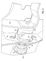
- an end of the housing 36 is inserted through an attachment area or opening 54 in a vehicle body 52, such as shown in Figure 3 .
- the plate 40 is provided on the inside of the attachment area 54, surrounding at least part of the cylindrical body 37 of the housing 36.
- the tap holes or openings 46 of the plate 40 are then aligned within the openings in the attachment area 54 on the vehicle body 52.
- the bracket 38 is then applied to the outside of the attachment area 54, and openings 44 are aligned with the openings in the attachment area 54 and plate 40.
- the openings 44 in bracket 38 and the openings 46 in plate 40 may thus be aligned with vehicle body 52 therebetween and joined using securing devices 43 such as bolts, for example.
- the bolts 43 are threaded through the side of a vehicle truck bed 52 and into the extruded tap holes 46 of the plate 40 for securement of the motion assist device 10.
- FIGS 2 and 3 when the motion assist device is attached the vehicle body 52 and the tailgate is in a raised, closed position, the resilient member 24 is at rest or in a relaxed condition. The device may not be fully released, and still under some compression.
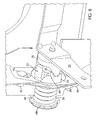
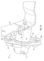
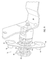
- Figures 4 , 5 , and 6 illustrate a detailed view of the rotation biasing of resilient member and the interaction and cooperation of the engagement surfaces 21, 23 of the first and second cams 20, 22 during rotation of the tailgate. As the tailgate is rotated along the pivot axis A from a raised position to a lowered position, the engagement surface 21 of the first cam 20 rotates relative to the engagement surface 23 of the second cam 22.
- FIG. 4 shows the action of the motion assist device 10 when the tailgate is rotated open at about 30 degrees.
- the resilient member 24 is further compressed along pivot axis A.
- resilient member 24 is compressed as second cam 22 moves along shaft 26 and into vehicle body 52, such as represented by an opening of the tailgate to about 60 degrees as shown in Figure 5 .
- the sloped engagement surface 21 of first cam 20 is shown pivotally moving relative to the pivot axis A and along with tailgate with respect to the rotatably fixed second cam 22.
- the rotation of the first cam 20 relative to the second cam 22 forces the second cam 22 to translate outwardly (e.g., into vehicle body 52), thus forcing the resilient member 24 to compress between the end 48a of the guide post 48 and the second cam 22 (see Figures 5 and 6 ).
- the reaction force pushing back on cam 22 is translated by the engagement of surfaces 21, 23 into a force on cam 20 and the tailgate in the closing direction. This relieves some of the load of the tailgate as it is being lowered.
- the resilient member 24 When the tailgate is in a lowered position, as shown in Figures 6 and 7 , the resilient member 24 is in a compressed condition. The compression of the resilient member 24 forces the resilient member 24 to store potential energy that will be transformed into kinetic energy (i.e., a force or torque) that will be transferred to the tailgate to assist in closing the vehicle tailgate 12.
- kinetic energy i.e., a force or torque
- the resilient member 24 is decompressed, releasing its stored potential energy and transforming it to kinetic energy to provide a lift or motion assist torque through the movement of cam 22 and rotation of the cam 20, bracket 28 and other elements via axis A.
- Figures 6 and 7 also show an embodiment wherein the second cam 22 comprises a detent 60.
- the detent 60 is provided on the engagement surface 23 of second cam 22.
- the detent 60 is provided to releasably lock the tailgate at an angle in the open position. Locking the engagement surfaces 21, 23 together using detent 60 at an angled position prevents the tailgate from moving or bouncing while in the open position.
- the detent 60 may be provided at a location on the second cam 22 corresponding to when the tailgate is lowered or open near approximately 80 degrees (with respect to the vehicle body or truck bed).
- the sloped engagement surface 21 of the first cam 20 rotates over the sloped engagement surface 23 of cam 22 and into detent 60, thus mating and locking the surface 21 of cam 20 within the detent 60.
- the tailgate is therefore maintained at an angled position with respect to the vehicle body 52.
- the resilient member 24 extends and relaxes a predetermined amount, thus preventing the tailgate from rotating closed (or open) without some effort or force sufficient to compress the spring for allowing cam 20 to clear the protrusion of detent 60. This is beneficial for limiting bouncing of the tailgate in the fully open position.
- the motion assist device 10 then provides the previously described lift or torque assist for closing the tailgate.
- the detent 60 may be provided such that it holds the tailgate in any angled position.
- the tailgate may be held at a lowered, open position, such as greater than 90 degrees.
- the user provides the required effort to close the tailgate, and, when the tailgate is open approximately 75 degrees, the first cam 20 is free to rotate with respect to second cam 22, thus providing motion assistance to the user to close the tailgate.
- any number of detents may be provided on the second cam 22 such that the tailgate may be locked in any number of angled positions.
- the design of the motion assist device 10 is compact and thus provides a user with the ability to easily package the device in the vehicle body and tailgate as compared to other designs.
- the use of the bracket 38 in the side of the vehicle body is easily assembled with fastening devices such as M10 bolts at a customer plant or facility, as opposed to two separate operations that may be required when assembling other torque rod devices.
- the motion assist device 10 is easily serviceable and does not require special service components or access to the tailgate when in need of service or repair.
- the design is advantageous as it decreases the production steps, the amount of time for assembly, and overall costs (e.g., labor).
- the speed of opening the tailgate in the motion assist device 10 may be decreased in an embodiment. If desired, the motion assist device 10 may be adjusted such that a user must provide some effort to open the tailgate into the lowered, open position. For example, since the motion of rotating the tailgate increases the frictional forces between the cams 20, 22 and the compression of the resilient member 24, and the motion assist device 10 may require an increase in force per degree of rotation by the user when opening the tailgate.
- the resilient member 24 may be provided to relieve some of the weight of the tailgate.
- the motion assist device 10 may be provided on one hinge mechanism that pivotally mounts the closure member or tailgate for movement about the pivot axis A with respect to the vehicle body. In an alternate embodiment, the motion assist device 10 is provided on each hinge mechanism on opposing sides of the tailgate.
- the motion assist device 10 may be provided to work in cooperation with a torque rod lift assist system to provide additional lift assistance to a tailgate.
- FIG 8 is a detailed view of a housing 76 and guide post 78 for a motion assist device 70 for use in a vehicle tailgate in accordance with an embodiment of the present invention.
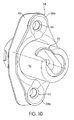
- the motion assist device 70 of Figure 8 comprises a notch 72 within the housing 76, shown in detail in Figure 10 .
- the notch 72 is provided in the housing 76 to assist in engaging the bracket 28 with the housing 76.
- the notch 72 assists in providing ease of removing a tailgate, such as when a tailgate needs to be removed from a vehicle body for repair or other known reasons.
- Figure 9 shows a detailed view of the motion assist mechanism 78 within the motion assist device 70 of Figure 8 .
- the design, features, and elements of motion assist mechanism 78 provides a substantially similar design, features, and elements as previously described with reference to Figures 2-7 .
- the motion assist device 70 allows for using the cam devices as a dampening mechanism as well as for locking a tailgate into open positions by using a detents 80, 82.
- the motion assist device 70 may also be used in conjunction with a torque rod lift assist system, such as the system and method described in U.S. Patent Application Serial No. 60/780,858, filed March 10, 2006 .
- motion assist device 70 may be smaller in size and allow for easier packaging within the available space (e.g., in the vehicle body or in the tailgate).
- the above described components of the motion assist device 10 are not meant to be limiting.
- seals, liners, or other devices may be provided to reduce friction, noise and wear between the parts of the motion assist device 10.
- the materials used in the device 10 should not be limiting.
Landscapes
- Engineering & Computer Science (AREA)
- Chemical & Material Sciences (AREA)
- Combustion & Propulsion (AREA)
- Transportation (AREA)
- Mechanical Engineering (AREA)
- Closing And Opening Devices For Wings, And Checks For Wings (AREA)
- Lock And Its Accessories (AREA)
Applications Claiming Priority (1)
| Application Number | Priority Date | Filing Date | Title |
|---|---|---|---|
| US96842007P | 2007-08-28 | 2007-08-28 |
Publications (2)
| Publication Number | Publication Date |
|---|---|
| EP2030873A2 true EP2030873A2 (fr) | 2009-03-04 |
| EP2030873A3 EP2030873A3 (fr) | 2014-02-19 |
Family
ID=40039891
Family Applications (1)
| Application Number | Title | Priority Date | Filing Date |
|---|---|---|---|
| EP08163170.7A Withdrawn EP2030873A3 (fr) | 2007-08-28 | 2008-08-28 | Mécanisme à charnière pour véhicule |
Country Status (2)
| Country | Link |
|---|---|
| US (1) | US7699378B2 (fr) |
| EP (1) | EP2030873A3 (fr) |
Cited By (3)
| Publication number | Priority date | Publication date | Assignee | Title |
|---|---|---|---|---|
| WO2016175713A1 (fr) * | 2015-04-27 | 2016-11-03 | Honglawan Chidchanok | Charnière de hayon arrière économisant du travail |
| GB2620214A (en) * | 2021-07-01 | 2024-01-03 | Austin Hardware & Supply Inc | Counterbalance hinge assembly |
| US12270235B2 (en) | 2021-07-01 | 2025-04-08 | Austin Hardware & Supply, Inc. | Counterbalance hinge assembly |
Families Citing this family (24)
| Publication number | Priority date | Publication date | Assignee | Title |
|---|---|---|---|---|
| US20080201903A1 (en) * | 2007-02-22 | 2008-08-28 | Anderson-Cook, Inc. | Counterbalance hinge for vehicle closure |
| US7699378B2 (en) * | 2007-08-28 | 2010-04-20 | Ventra Group, Inc. | Motion assist mechanism for a vehicle tailgate |
| US7673929B2 (en) * | 2007-10-10 | 2010-03-09 | Ventra Group, Inc. | Hinge with a viscous rotary damper |
| US7850219B2 (en) * | 2008-10-08 | 2010-12-14 | Gm Global Technology Operations, Inc. | Viscous rotary damper for vehicle end gate assembly |
| DE102010023971B3 (de) * | 2010-06-16 | 2011-12-08 | Audi Ag | Verfahren zum Einbau einer Vorrichtung zum federunterstützten Verschwenken einer Klappe oder Tür in ein Fahrzeug |
| US8540305B2 (en) * | 2011-03-23 | 2013-09-24 | GM Global Technology Operations LLC | Hollow torque rod for a closure panel |
| US9528309B2 (en) * | 2012-10-15 | 2016-12-27 | Husqvarna Ab | Outdoor power equipment hood hinge |
| US8827348B2 (en) * | 2013-02-08 | 2014-09-09 | Deere & Company | Self locking and unlocking hinge |
| US10093362B2 (en) * | 2015-12-15 | 2018-10-09 | Inteva Products, Llc | Vehicle tailgate latch and tailgate system |
| US10145164B2 (en) | 2016-10-27 | 2018-12-04 | Ford Global Technologies, Llc | Vehicle tailgate assembly |
| US10029598B2 (en) | 2016-12-27 | 2018-07-24 | Theodore J. Keck | Hitch-mounted carrier system with ramp |
| US10981679B2 (en) | 2017-08-04 | 2021-04-20 | Rocket Lab Usa, Inc. | Satellite deployer door release mechanism |
| US10822855B2 (en) | 2017-12-22 | 2020-11-03 | Toyota Motor Engineering & Manufacturing North America, Inc. | Power back door bounce prevention to allow maximum opening speed |
| US10358171B1 (en) * | 2018-01-11 | 2019-07-23 | Ford Global Technologies, Llc | Tailgate anti-chuck assembly |
| US11435024B2 (en) * | 2018-06-27 | 2022-09-06 | Lianhong Art Co., Ltd. | Rebounding pivot module |
| US10974656B2 (en) | 2019-05-10 | 2021-04-13 | Theodore J. Keck | Pickup truck tailgate storage carrier and resting surface |
| US11111710B2 (en) * | 2019-06-18 | 2021-09-07 | Fca Us Llc | Vehicle having hinge assembly |
| EP3839182B1 (fr) * | 2019-12-19 | 2024-03-27 | Ningbo Geely Automobile Research & Development Co. Ltd. | Charnière pour une porte de véhicule, charnière de hayon, charnière de porte latérale et véhicule |
| CN114684278B (zh) * | 2020-12-31 | 2023-05-12 | 北汽福田汽车股份有限公司 | 货箱及车辆 |
| US12359469B2 (en) * | 2021-10-21 | 2025-07-15 | Schlage Lock Company Llc | Anti-barricade assembly |
| KR102784320B1 (ko) * | 2021-12-20 | 2025-03-20 | 멀티매틱 인코퍼레이티드 | 도어 닫기 돕는 기능을 가진 자동차 도어 힌지 |
| US12473763B2 (en) | 2022-08-23 | 2025-11-18 | Reell Precision Manufacturing Corporation | Detent hinge |
| US20250043605A1 (en) * | 2023-07-31 | 2025-02-06 | GM Global Technology Operations LLC | Cable-less end gate for a vehicle |
| US12497811B2 (en) * | 2023-12-01 | 2025-12-16 | Caterpillar Inc. | Door hinge cushioning arrangement |
Citations (1)
| Publication number | Priority date | Publication date | Assignee | Title |
|---|---|---|---|---|
| US6769729B1 (en) | 2003-06-25 | 2004-08-03 | Ford Global Technologies, Llc | Automotive tailgate with lift assist system-I |
Family Cites Families (55)
| Publication number | Priority date | Publication date | Assignee | Title |
|---|---|---|---|---|
| US365158A (en) * | 1887-06-21 | Tusten van dtjzer | ||
| US571133A (en) * | 1896-11-10 | Spring-hinge | ||
| US1356039A (en) * | 1920-10-19 | Betaining-hinge fob bubeatj-mibbobs | ||
| US771608A (en) * | 1902-12-01 | 1904-10-04 | George H Forsyth | Fastener for deck or other sashes. |
| US757805A (en) * | 1903-11-16 | 1904-04-19 | William Dunstan Ford-Smith | Clutch mechanism. |
| US1078002A (en) * | 1911-09-18 | 1913-11-11 | Frederick Schrey | Hinge. |
| US3085286A (en) * | 1955-10-19 | 1963-04-16 | Alexander Squire Ltd | Hinge |
| US2890477A (en) * | 1957-04-12 | 1959-06-16 | Soss Mfg Company | Door check and hold open |
| US3031225A (en) * | 1959-02-11 | 1962-04-24 | Chrysler Corp | Tailgate mounting |
| US2984517A (en) * | 1959-11-18 | 1961-05-16 | Chrysler Corp | Torsion bar tailgate support |
| US3166783A (en) * | 1962-04-05 | 1965-01-26 | Gen Motors Corp | Door hinge mechanism |
| US3258289A (en) * | 1963-10-07 | 1966-06-28 | Gen Motors Corp | Vehicle seat |
| US3243175A (en) * | 1964-03-18 | 1966-03-29 | Gen Motors Corp | Torsion spring attachment means |
| US3518716A (en) * | 1968-05-24 | 1970-07-07 | Keystone Consolidated Ind Inc | Self-closing hinge |
| US3656801A (en) * | 1970-05-14 | 1972-04-18 | Oliver Doutt | Quickly detachable hinge for truck body tailgate |
| US3815685A (en) * | 1972-11-27 | 1974-06-11 | E Seifert | Torsion bar clamp |
| US3848918A (en) * | 1973-03-12 | 1974-11-19 | Rewop Co | Tailgate release |
| JPS5355819A (en) * | 1976-10-09 | 1978-05-20 | Honda Motor Co Ltd | Device for correcting characteristics of suspension pneumatic spring for vehicle |
| DE10118301B4 (de) * | 2001-04-12 | 2011-01-20 | Brückner, Lothar, Dr. | Kraftwagentürscharnier |
| US4215449A (en) * | 1978-09-15 | 1980-08-05 | Standard Keil Hardware Manufacturing Co. | Self-closing hinge |
| US4421333A (en) * | 1981-05-14 | 1983-12-20 | Monsanto Company | Assembly for mounting a vehicle spray suppression device |
| US4589164A (en) * | 1984-06-08 | 1986-05-20 | Airpot Corporation | Variable tension device with adjustable features for spring rate, initial tension and connection to external parts |
| JPS6217282A (ja) * | 1985-07-15 | 1987-01-26 | 株式会社 大井製作所 | トラツクにおける荷台のゲ−トヒンジ装置 |
| AU624027B2 (en) * | 1989-10-11 | 1992-05-28 | Sugatsune Industrial Co., Ltd | Door hinge |
| US5138743A (en) * | 1991-06-21 | 1992-08-18 | White Consolidated Industries, Inc. | Refrigerator door closing device |
| GB9317431D0 (en) * | 1993-08-21 | 1993-10-06 | Kason Harware Uk Limited | Hinge assembly |
| US5358301A (en) * | 1993-11-22 | 1994-10-25 | General Motors Corporation | Counterbalance mechanism for a removable tailgate |
| US5682644A (en) * | 1996-02-06 | 1997-11-04 | Component Hardware Group, Inc. | Hinge assembly |
| JPH10131947A (ja) * | 1996-10-28 | 1998-05-22 | Kato Electrical Mach Co Ltd | 複合トルクヒンジ |
| JP3691630B2 (ja) * | 1997-04-21 | 2005-09-07 | 加藤電機株式会社 | 開閉体の開閉装置 |
| US5966776A (en) * | 1997-05-07 | 1999-10-19 | Strawberry Corporation | Hinge device |
| US5799371A (en) * | 1997-05-20 | 1998-09-01 | Tamarack Technologies Inc. | Pivoting joint |
| US5988724A (en) * | 1997-08-15 | 1999-11-23 | Wolda; Tiete O. | Tailgate hinge mechanism |
| US5944373A (en) * | 1998-08-18 | 1999-08-31 | Aluminum Company Of America | Lightweight tailgate assembly |
| SE520776C2 (sv) * | 1999-07-07 | 2003-08-26 | Volvo Car Corp | Stoppanordning för att stoppa en kring en vridaxel svängbar lucka |
| IT1320288B1 (it) * | 2000-03-29 | 2003-11-26 | Gammastamp Spa | Cerniera per porte di veicoli con dispositivo fermaporta integrato. |
| US20030189354A1 (en) * | 2002-04-09 | 2003-10-09 | Ventra Group Inc. | Hinge assembly and method for manufacturing same |
| US7096536B2 (en) * | 2002-06-07 | 2006-08-29 | Illinois Tool Works Inc | Hinge apparatus with check mechanism |
| US6637796B1 (en) * | 2002-11-22 | 2003-10-28 | Midway Products Group, Inc. | Vehicle tailgate hinge and counterbalance assembly |
| US6796592B1 (en) * | 2003-03-12 | 2004-09-28 | M & C Corporation | Tailgate counterbalancing hinge |
| US6846030B2 (en) * | 2003-06-25 | 2005-01-25 | Ford Global Technologies, Llc | Vehicle closure panel with torsion bar assist and integral vibration damping |
| US6874837B2 (en) * | 2003-06-25 | 2005-04-05 | Ford Global Technologies, Llc | Lift assisted tailgate system for automotive vehicle |
| US6905156B2 (en) * | 2003-06-25 | 2005-06-14 | Ford Global Technologies, Llc | Automotive closure panel with pivot-mounted alignment system |
| US6793263B1 (en) * | 2003-06-25 | 2004-09-21 | Ford Global Technologies, Llc | Pickup truck with lift assisted tailgate system |
| CN100340734C (zh) * | 2004-03-05 | 2007-10-03 | 三星电子株式会社 | 用于储藏容器的铰链装置和具有其的储藏容器 |
| EP1748920A4 (fr) * | 2004-03-10 | 2009-11-11 | M & C Corp | Articulation d'equilibrage de panneau arriere |
| KR20070027576A (ko) * | 2004-06-08 | 2007-03-09 | 암페놀 티 앤드 엠 안테나즈 | 휴대 장치용 평행 평판 회전 힌지 |
| US7213858B2 (en) * | 2005-03-31 | 2007-05-08 | Nissan Technical Center North America, Inc. | Tailgate support structure with lateral tailgate adjustment |
| US20060249343A1 (en) * | 2005-05-06 | 2006-11-09 | Suspa Holding Gmbh | Rotary damper |
| US20070152471A1 (en) * | 2005-07-21 | 2007-07-05 | Zagoroff Dimiter S | Truck tailgate with internal motion control devices |
| CN1916434B (zh) * | 2005-08-19 | 2010-06-02 | 深圳富泰宏精密工业有限公司 | 铰链结构及应用该铰链结构的便携式电子装置 |
| JP4734283B2 (ja) * | 2006-11-17 | 2011-07-27 | 本田技研工業株式会社 | 車両のチェック機能付きドアヒンジ |
| US7699378B2 (en) * | 2007-08-28 | 2010-04-20 | Ventra Group, Inc. | Motion assist mechanism for a vehicle tailgate |
| US7596830B2 (en) * | 2007-09-06 | 2009-10-06 | Cheng Uei Precision Industry Co., Ltd. | Hinge |
| US7631397B2 (en) * | 2007-09-06 | 2009-12-15 | Cheng Uei Precision Industry Co., Ltd. | Hinge |
-
2008
- 2008-08-27 US US12/199,303 patent/US7699378B2/en active Active
- 2008-08-28 EP EP08163170.7A patent/EP2030873A3/fr not_active Withdrawn
Patent Citations (1)
| Publication number | Priority date | Publication date | Assignee | Title |
|---|---|---|---|---|
| US6769729B1 (en) | 2003-06-25 | 2004-08-03 | Ford Global Technologies, Llc | Automotive tailgate with lift assist system-I |
Cited By (4)
| Publication number | Priority date | Publication date | Assignee | Title |
|---|---|---|---|---|
| WO2016175713A1 (fr) * | 2015-04-27 | 2016-11-03 | Honglawan Chidchanok | Charnière de hayon arrière économisant du travail |
| GB2620214A (en) * | 2021-07-01 | 2024-01-03 | Austin Hardware & Supply Inc | Counterbalance hinge assembly |
| US12270238B2 (en) | 2021-07-01 | 2025-04-08 | Austin Hardware & Supply, Inc. | Counterbalance hinge assembly |
| US12270235B2 (en) | 2021-07-01 | 2025-04-08 | Austin Hardware & Supply, Inc. | Counterbalance hinge assembly |
Also Published As
| Publication number | Publication date |
|---|---|
| EP2030873A3 (fr) | 2014-02-19 |
| US7699378B2 (en) | 2010-04-20 |
| US20090058131A1 (en) | 2009-03-05 |
Similar Documents
| Publication | Publication Date | Title |
|---|---|---|
| EP2030873A2 (fr) | Mécanisme à charnière pour véhicule | |
| KR100758154B1 (ko) | 차량뒷문 리프트어시스트 구조 | |
| US5743575A (en) | Fluid-damped automotive door latch actuator | |
| US8413382B2 (en) | Hinge and door unit | |
| US6155616A (en) | Locking mechanism and closure assembly including same | |
| RU2471950C2 (ru) | Стопорное устройство с накапливающим энергию корпусом для двери автомобиля | |
| US9482041B2 (en) | Door actuator | |
| US4097958A (en) | Rubber torsion spring hood hinge for automotive vehicle | |
| EP1598512A2 (fr) | Réfrigérateur | |
| CN103648813A (zh) | 车辆用开闭体的振动防止装置及车辆用开闭体的止动装置 | |
| US20090301146A1 (en) | Slam latch for toolbox | |
| WO2004081327A1 (fr) | Articulation d'equilibrage de panneau arriere | |
| CN101253301A (zh) | 用于车辆的车门打开/关闭装置 | |
| JPH0260824A (ja) | 自動車用ドア構造 | |
| US7731165B2 (en) | Hood support | |
| US8978203B2 (en) | Decklid hinge assembly for a vehicle | |
| US20220251888A1 (en) | Rotary actuated slam latch system | |
| EP0856628A1 (fr) | Ferme-porte | |
| CN1938494A (zh) | 带阻尼器的铰链 | |
| WO2020220114A1 (fr) | Ensemble cage de rotule avec élément anti-rotation | |
| EP0781675A1 (fr) | Structure pour relever par ressort une porte de camion de type fourgon | |
| US6669066B2 (en) | Holding device for a spare wheel of a motor vehicle | |
| KR101218244B1 (ko) | 차량의 적재함도어 개폐장치 | |
| KR100878599B1 (ko) | 화물차용 적재함 사이드 게이트의 개폐 보조장치 | |
| CA2696598C (fr) | Support de capot |
Legal Events
| Date | Code | Title | Description |
|---|---|---|---|
| PUAI | Public reference made under article 153(3) epc to a published international application that has entered the european phase |
Free format text: ORIGINAL CODE: 0009012 |
|
| AK | Designated contracting states |
Kind code of ref document: A2 Designated state(s): AT BE BG CH CY CZ DE DK EE ES FI FR GB GR HR HU IE IS IT LI LT LU LV MC MT NL NO PL PT RO SE SI SK TR |
|
| AX | Request for extension of the european patent |
Extension state: AL BA MK RS |
|
| PUAL | Search report despatched |
Free format text: ORIGINAL CODE: 0009013 |
|
| AK | Designated contracting states |
Kind code of ref document: A3 Designated state(s): AT BE BG CH CY CZ DE DK EE ES FI FR GB GR HR HU IE IS IT LI LT LU LV MC MT NL NO PL PT RO SE SI SK TR |
|
| AX | Request for extension of the european patent |
Extension state: AL BA MK RS |
|
| RIC1 | Information provided on ipc code assigned before grant |
Ipc: B62D 33/03 20060101AFI20140116BHEP |
|
| AKY | No designation fees paid | ||
| REG | Reference to a national code |
Ref country code: DE Ref legal event code: R108 |
|
| REG | Reference to a national code |
Ref country code: DE Ref legal event code: R108 Effective date: 20141022 |
|
| STAA | Information on the status of an ep patent application or granted ep patent |
Free format text: STATUS: THE APPLICATION IS DEEMED TO BE WITHDRAWN |
|
| 18D | Application deemed to be withdrawn |
Effective date: 20140820 |