EP2031196A2 - Moteur à combustion interne - Google Patents
Moteur à combustion interne Download PDFInfo
- Publication number
- EP2031196A2 EP2031196A2 EP08014401A EP08014401A EP2031196A2 EP 2031196 A2 EP2031196 A2 EP 2031196A2 EP 08014401 A EP08014401 A EP 08014401A EP 08014401 A EP08014401 A EP 08014401A EP 2031196 A2 EP2031196 A2 EP 2031196A2
- Authority
- EP
- European Patent Office
- Prior art keywords
- camshaft
- valve
- exhaust
- intake
- working cylinder
- Prior art date
- Legal status (The legal status is an assumption and is not a legal conclusion. Google has not performed a legal analysis and makes no representation as to the accuracy of the status listed.)
- Withdrawn
Links
- 238000002485 combustion reaction Methods 0.000 title claims abstract description 12
- RDYMFSUJUZBWLH-UHFFFAOYSA-N endosulfan Chemical compound C12COS(=O)OCC2C2(Cl)C(Cl)=C(Cl)C1(Cl)C2(Cl)Cl RDYMFSUJUZBWLH-UHFFFAOYSA-N 0.000 description 6
- 239000007789 gas Substances 0.000 description 6
- MWUXSHHQAYIFBG-UHFFFAOYSA-N nitrogen oxide Inorganic materials O=[N] MWUXSHHQAYIFBG-UHFFFAOYSA-N 0.000 description 3
- 239000003054 catalyst Substances 0.000 description 2
- 238000010531 catalytic reduction reaction Methods 0.000 description 1
- 230000006835 compression Effects 0.000 description 1
- 238000007906 compression Methods 0.000 description 1
Images


Classifications
-
- F—MECHANICAL ENGINEERING; LIGHTING; HEATING; WEAPONS; BLASTING
- F01—MACHINES OR ENGINES IN GENERAL; ENGINE PLANTS IN GENERAL; STEAM ENGINES
- F01L—CYCLICALLY OPERATING VALVES FOR MACHINES OR ENGINES
- F01L1/00—Valve-gear or valve arrangements, e.g. lift-valve gear
- F01L1/34—Valve-gear or valve arrangements, e.g. lift-valve gear characterised by the provision of means for changing the timing of the valves without changing the duration of opening and without affecting the magnitude of the valve lift
-
- F—MECHANICAL ENGINEERING; LIGHTING; HEATING; WEAPONS; BLASTING
- F01—MACHINES OR ENGINES IN GENERAL; ENGINE PLANTS IN GENERAL; STEAM ENGINES
- F01L—CYCLICALLY OPERATING VALVES FOR MACHINES OR ENGINES
- F01L1/00—Valve-gear or valve arrangements, e.g. lift-valve gear
- F01L1/02—Valve drive
- F01L1/04—Valve drive by means of cams, camshafts, cam discs, eccentrics or the like
- F01L1/047—Camshafts
- F01L1/053—Camshafts overhead type
-
- F—MECHANICAL ENGINEERING; LIGHTING; HEATING; WEAPONS; BLASTING
- F01—MACHINES OR ENGINES IN GENERAL; ENGINE PLANTS IN GENERAL; STEAM ENGINES
- F01L—CYCLICALLY OPERATING VALVES FOR MACHINES OR ENGINES
- F01L1/00—Valve-gear or valve arrangements, e.g. lift-valve gear
- F01L1/26—Valve-gear or valve arrangements, e.g. lift-valve gear characterised by the provision of two or more valves operated simultaneously by same transmitting-gear; peculiar to machines or engines with more than two lift-valves per cylinder
-
- F—MECHANICAL ENGINEERING; LIGHTING; HEATING; WEAPONS; BLASTING
- F02—COMBUSTION ENGINES; HOT-GAS OR COMBUSTION-PRODUCT ENGINE PLANTS
- F02D—CONTROLLING COMBUSTION ENGINES
- F02D13/00—Controlling the engine output power by varying inlet or exhaust valve operating characteristics, e.g. timing
- F02D13/02—Controlling the engine output power by varying inlet or exhaust valve operating characteristics, e.g. timing during engine operation
- F02D13/0203—Variable control of intake and exhaust valves
- F02D13/0207—Variable control of intake and exhaust valves changing valve lift or valve lift and timing
-
- F—MECHANICAL ENGINEERING; LIGHTING; HEATING; WEAPONS; BLASTING
- F02—COMBUSTION ENGINES; HOT-GAS OR COMBUSTION-PRODUCT ENGINE PLANTS
- F02D—CONTROLLING COMBUSTION ENGINES
- F02D13/00—Controlling the engine output power by varying inlet or exhaust valve operating characteristics, e.g. timing
- F02D13/02—Controlling the engine output power by varying inlet or exhaust valve operating characteristics, e.g. timing during engine operation
- F02D13/0257—Independent control of two or more intake or exhaust valves respectively, i.e. one of two intake valves remains closed or is opened partially while the other is fully opened
-
- F—MECHANICAL ENGINEERING; LIGHTING; HEATING; WEAPONS; BLASTING
- F02—COMBUSTION ENGINES; HOT-GAS OR COMBUSTION-PRODUCT ENGINE PLANTS
- F02D—CONTROLLING COMBUSTION ENGINES
- F02D13/00—Controlling the engine output power by varying inlet or exhaust valve operating characteristics, e.g. timing
- F02D13/02—Controlling the engine output power by varying inlet or exhaust valve operating characteristics, e.g. timing during engine operation
- F02D13/0261—Controlling the valve overlap
- F02D13/0265—Negative valve overlap for temporarily storing residual gas in the cylinder
-
- Y—GENERAL TAGGING OF NEW TECHNOLOGICAL DEVELOPMENTS; GENERAL TAGGING OF CROSS-SECTIONAL TECHNOLOGIES SPANNING OVER SEVERAL SECTIONS OF THE IPC; TECHNICAL SUBJECTS COVERED BY FORMER USPC CROSS-REFERENCE ART COLLECTIONS [XRACs] AND DIGESTS
- Y02—TECHNOLOGIES OR APPLICATIONS FOR MITIGATION OR ADAPTATION AGAINST CLIMATE CHANGE
- Y02T—CLIMATE CHANGE MITIGATION TECHNOLOGIES RELATED TO TRANSPORTATION
- Y02T10/00—Road transport of goods or passengers
- Y02T10/10—Internal combustion engine [ICE] based vehicles
- Y02T10/12—Improving ICE efficiencies
Definitions
- the invention relates to an internal combustion engine, in particular a diesel engine, in particular a motor vehicle, with at least one working cylinder, wherein each working cylinder is associated with a first and a second inlet valve and a first and a second exhaust valve, wherein at least two camshafts are provided, of which a first camshaft both at least one inlet valve and at least one exhaust valve actuated, wherein on the first camshaft, a first camshaft adjuster is arranged, which valve timing of the first camshaft associated intake and exhaust valves selectively adjusted to early or late, according to the preamble of claim 1.
- the invention has for its object to improve a variable valve train of an internal combustion engine, in particular a diesel engine.
- the first camshaft is arranged and configured such that it actuates the first inlet valve and the first exhaust valve of each cylinder, wherein a second camshaft is provided, which actuates the second inlet valve and the second exhaust valve of each working cylinder, wherein the second camshaft, a second camshaft adjuster is arranged, which valve timing of the second camshaft associated intake and exhaust valves selectively adjusted to early or late.
- valve timing can be varied over a wide range during the charge cycle for each cylinder for both the inlet and the outlet.
- a direct influence on the internal exhaust gas recirculation with optionally high proportion of internal exhaust gas recirculation is achieved by the fact that at a position of the camshaft adjuster in a central position between the maximum end positions of early and late, a negative valve overlap is more than 40 ° CA.
- the first and / or second phaser for example, is designed such that it has an adjustment range for the valve timing of +/- 20 ° CA.
- FIG. 1 Only schematically illustrated, preferred embodiment of an internal combustion engine according to the invention with working cylinders, not shown, each of which has a first and second inlet valve (not shown) and a first and second exhaust valve (not shown), comprises a first camshaft 10 with a first camshaft adjuster 12 and a second camshaft 14 with a second phaser 16.
- the first camshaft 10 actuates the first intake valve and the first exhaust valve of each working cylinder and the second camshaft 14 actuates the second intake valve and the second exhaust valve of each working cylinder.
- the camshafts 10, 14 are driven by a crankshaft 18 via a toothed belt or chain 20.
- the two camshaft adjusters 12, 16 are arranged and configured such that they each adjust a camshaft independently of the other camshaft from a centered position optionally to early or late.
- Fig. 2 illustrates the timing for first and second intake valve and first and second exhaust valve of a working cylinder through the first and second camshaft 10, 14.
- a crank angle is plotted on a horizontal axis 28 and a stroke on a vertical axis 30.
- a piston oscillating in the power cylinder reaches a bottom dead center UT after a power stroke and before a charge cycle
- the piston reaches a top dead center OT in the charge cycle
- at 26 the piston reaches bottom dead center UT after a charge swing and before a compression stroke.
- a first graph 32 illustrates the lift of the first exhaust valve through the crank angle
- a second graph 34 illustrates the lift of the first intake valve versus the crank angle
- a third graph 36 illustrates the lift of the second exhaust valve versus the crank angle
- a fourth graph 38 illustrates the lift of the crank second intake valve via the crank angle.
- the first exhaust valve and first intake valve graphs 32 and 34 are determined by the first crankshaft 1.0
- the second exhaust valve and second intake valve graphs 36 and 38 are determined by the second crankshaft 14.
- a fifth graph 40 illustrates the stroke of the piston.
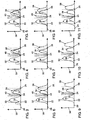
- Fig. 3 to 11 show the timing for the gas exchange valves of a working piston for nine different positions of the camshaft adjuster.
- Fig. 3 are the first and second camshaft adjuster 12, 16 adjusted to early. This results in a mean valve overlap before OT 24.
- Fig. 4 the first camshaft adjuster 12 of the first camshaft 10 is centered and the second camshaft adjuster 16 of the second camshaft 14 is advanced. This results in a small valve overlap in the area of the OT 24.
- Fig. 5 the first camshaft adjuster 12 of the first camshaft 10 is retarded and the second camshaft adjuster 16 of the second camshaft 14 is advanced. This results in a minimum valve overlap.
- Fig. 3 are the first and second camshaft adjuster 12, 16 adjusted to early. This results in a mean valve overlap before OT 24.
- Fig. 4 the first camshaft adjuster 12 of the first camshaft 10 is centered and the second camshaft adjuster 16 of the second camshaft
- the first camshaft adjuster 12 of the first camshaft 10 is centered and the second camshaft adjuster 16 of the second camshaft 14 is retarded. This results in a small valve overlap in the area of the OT 24.
- the first and second phaser 12, 16 are retarded. This results in a mean valve overlap in the range of OT 24.
- an optional repositioning of the closing time of the first exhaust valve by about 20 ° CA to early with simultaneous repositioning of the opening time of the first intake valve by 20 ° CA provided for late.
- both the size of the valve overlap between minimum and maximum and the position of a middle overlap between early and late are adjustable.
Landscapes
- Engineering & Computer Science (AREA)
- Mechanical Engineering (AREA)
- General Engineering & Computer Science (AREA)
- Chemical & Material Sciences (AREA)
- Combustion & Propulsion (AREA)
- Valve-Gear Or Valve Arrangements (AREA)
- Output Control And Ontrol Of Special Type Engine (AREA)
Applications Claiming Priority (1)
| Application Number | Priority Date | Filing Date | Title |
|---|---|---|---|
| DE102007040697A DE102007040697A1 (de) | 2007-08-29 | 2007-08-29 | Brennkraftmaschine |
Publications (2)
| Publication Number | Publication Date |
|---|---|
| EP2031196A2 true EP2031196A2 (fr) | 2009-03-04 |
| EP2031196A3 EP2031196A3 (fr) | 2010-08-18 |
Family
ID=40057219
Family Applications (1)
| Application Number | Title | Priority Date | Filing Date |
|---|---|---|---|
| EP08014401A Withdrawn EP2031196A3 (fr) | 2007-08-29 | 2008-08-13 | Moteur à combustion interne |
Country Status (2)
| Country | Link |
|---|---|
| EP (1) | EP2031196A3 (fr) |
| DE (1) | DE102007040697A1 (fr) |
Cited By (2)
| Publication number | Priority date | Publication date | Assignee | Title |
|---|---|---|---|---|
| WO2014173480A1 (fr) * | 2013-04-26 | 2014-10-30 | Daimler Ag | Dispositif de commande de soupapes pour moteur à combustion interne |
| DE102010036774B4 (de) * | 2009-11-12 | 2016-02-04 | Hyundai Motor Co. | Benzinmotor mit Kompressionszündung |
Families Citing this family (2)
| Publication number | Priority date | Publication date | Assignee | Title |
|---|---|---|---|---|
| DE102011103870A1 (de) * | 2011-06-10 | 2012-12-13 | Volkswagen Aktiengesellschaft | Brennkraftmaschine |
| DE102014208950A1 (de) * | 2014-05-12 | 2015-11-12 | Volkswagen Aktiengesellschaft | Verbrennungsmotor und Verfahren zum Betreiben eines solchen Verbrennungsmotors |
Citations (1)
| Publication number | Priority date | Publication date | Assignee | Title |
|---|---|---|---|---|
| EP0947672A2 (fr) | 1998-04-02 | 1999-10-06 | DaimlerChrysler AG | Commande de soupape variable pour un moteur à combustion interne |
Family Cites Families (5)
| Publication number | Priority date | Publication date | Assignee | Title |
|---|---|---|---|---|
| DE59302331D1 (de) * | 1992-08-13 | 1996-05-30 | Bayerische Motoren Werke Ag | Hubkolben-Brennkraftmaschine mit zwei Gaswechselventilen je Zylinder |
| US6397813B1 (en) * | 2000-04-28 | 2002-06-04 | Ford Global Technologies, Inc. | Method and apparatus for inducing swirl in an engine cylinder by controlling engine valves |
| DE10122775A1 (de) * | 2000-05-18 | 2001-11-22 | Ford Global Tech Inc | Hybrider Motor und Verfahren zu dessen Taktsteuerung |
| DE102004020124A1 (de) * | 2004-04-24 | 2005-11-17 | Aft Atlas Fahrzeugtechnik Gmbh | Vorrichtung zur Einstellung von Ventilsteuerzeiten sowie Brennkraftmaschine mit einer derartigen Vorrichtung |
| FR2902833A1 (fr) * | 2006-06-21 | 2007-12-28 | Peugeot Citroen Automobiles Sa | Procede pour commander un moteur a combustion interne |
-
2007
- 2007-08-29 DE DE102007040697A patent/DE102007040697A1/de not_active Withdrawn
-
2008
- 2008-08-13 EP EP08014401A patent/EP2031196A3/fr not_active Withdrawn
Patent Citations (1)
| Publication number | Priority date | Publication date | Assignee | Title |
|---|---|---|---|---|
| EP0947672A2 (fr) | 1998-04-02 | 1999-10-06 | DaimlerChrysler AG | Commande de soupape variable pour un moteur à combustion interne |
Cited By (2)
| Publication number | Priority date | Publication date | Assignee | Title |
|---|---|---|---|---|
| DE102010036774B4 (de) * | 2009-11-12 | 2016-02-04 | Hyundai Motor Co. | Benzinmotor mit Kompressionszündung |
| WO2014173480A1 (fr) * | 2013-04-26 | 2014-10-30 | Daimler Ag | Dispositif de commande de soupapes pour moteur à combustion interne |
Also Published As
| Publication number | Publication date |
|---|---|
| EP2031196A3 (fr) | 2010-08-18 |
| DE102007040697A1 (de) | 2009-03-05 |
Similar Documents
| Publication | Publication Date | Title |
|---|---|---|
| EP2048331B1 (fr) | Moteur à combustion interne doté d'arbres à came mixtes | |
| EP2066874B1 (fr) | Moteur à combustion interne à arbres à cames mixtes | |
| EP3464857B1 (fr) | Procédé de fonctionnement d'un moteur à combustion interne et moteur à combustion interne | |
| EP2726721B1 (fr) | Moteur a combustion interne | |
| EP2500533B1 (fr) | Moteur à combustion interne doté d'un arbre à came mixte | |
| WO2013189698A1 (fr) | Procédé pour faire fonctionner un moteur à combustion interne selon le procédé d'autoallumage et moteur à combustion interne | |
| DE102005015852A1 (de) | Hubkolbenbrennkraftmaschine | |
| DE102014208950A1 (de) | Verbrennungsmotor und Verfahren zum Betreiben eines solchen Verbrennungsmotors | |
| DE102007040697A1 (de) | Brennkraftmaschine | |
| EP1680577B1 (fr) | Mecanisme de distribution de moteur a combustion interne comprenant au moins un arbre a cames | |
| EP2976512B1 (fr) | Moteur à combustion interne et procédé pour le faire fonctionner | |
| DE102012001316B4 (de) | Brennkraftmaschinenventiltriebvorrichtung | |
| DE102006002133B4 (de) | Ventiltrieb zur hubvariablen Betätigung eines Gaswechselventils einer Brennkraftmaschine | |
| DE102010051832B4 (de) | Verfahren zum Betreiben einer Hubkolben-Brennkraftmaschine mit Drallbrennverfahren | |
| DE102012206683B4 (de) | Ventiltrieb für einen Zylinderkopf einer Brennkraftmaschine | |
| DE102007049110B4 (de) | Brennkraftmaschine mit zwei gemischten Nockenwellen | |
| EP2532860B1 (fr) | Moteur à combustion interne | |
| EP3080430A1 (fr) | Moteur à pistons et procédé permettant de faire fonctionner ledit moteur | |
| DE102012212250A1 (de) | Verbrennungsmotor mit interner Verbrennung sowie Ventiltrieb eines solchen Motors | |
| EP3728818B1 (fr) | Procédé pour faire fonctionner un moteur à combustion interne et moteur à combustion interne | |
| DE102013222820A1 (de) | Hubvariabler Ventiltrieb eines Verbrennungsmotors | |
| DE102013007270A1 (de) | Ventiltriebvorrichtung für eine Brennkraftmaschine |
Legal Events
| Date | Code | Title | Description |
|---|---|---|---|
| PUAI | Public reference made under article 153(3) epc to a published international application that has entered the european phase |
Free format text: ORIGINAL CODE: 0009012 |
|
| AK | Designated contracting states |
Kind code of ref document: A2 Designated state(s): AT BE BG CH CY CZ DE DK EE ES FI FR GB GR HR HU IE IS IT LI LT LU LV MC MT NL NO PL PT RO SE SI SK TR |
|
| AX | Request for extension of the european patent |
Extension state: AL BA MK RS |
|
| PUAL | Search report despatched |
Free format text: ORIGINAL CODE: 0009013 |
|
| AK | Designated contracting states |
Kind code of ref document: A3 Designated state(s): AT BE BG CH CY CZ DE DK EE ES FI FR GB GR HR HU IE IS IT LI LT LU LV MC MT NL NO PL PT RO SE SI SK TR |
|
| AX | Request for extension of the european patent |
Extension state: AL BA MK RS |
|
| RIC1 | Information provided on ipc code assigned before grant |
Ipc: F01L 1/26 20060101ALI20100713BHEP Ipc: F01L 1/053 20060101ALI20100713BHEP Ipc: F02D 13/02 20060101ALI20100713BHEP Ipc: F01L 1/34 20060101AFI20081205BHEP |
|
| STAA | Information on the status of an ep patent application or granted ep patent |
Free format text: STATUS: THE APPLICATION HAS BEEN WITHDRAWN |
|
| 17P | Request for examination filed |
Effective date: 20110218 |
|
| 18W | Application withdrawn |
Effective date: 20110314 |